Since I already programmed my PCB with LEDs to work in week 5, I decided to make a new PCB that can be added to my car (which is going to be my final project).
I wanted to utilize this opportunity to make a car honk using a sensor. I could make a sensor that is based on force (which is difficult according to Anthony), capacitor, ultrasound (radiates throughout in a circular form), and light (using a laser and can detect in a straight line).
All of these options sounded interesting, and I decided to make a capacitor sensor and try a different form next time (maybe during the input devices week).
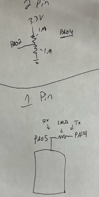
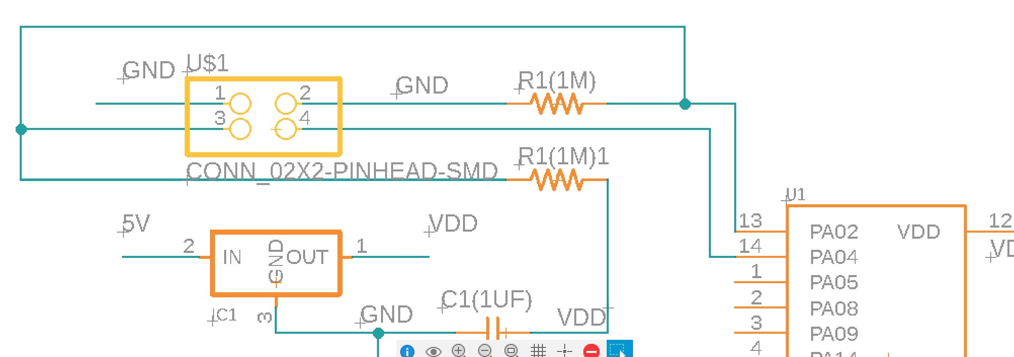
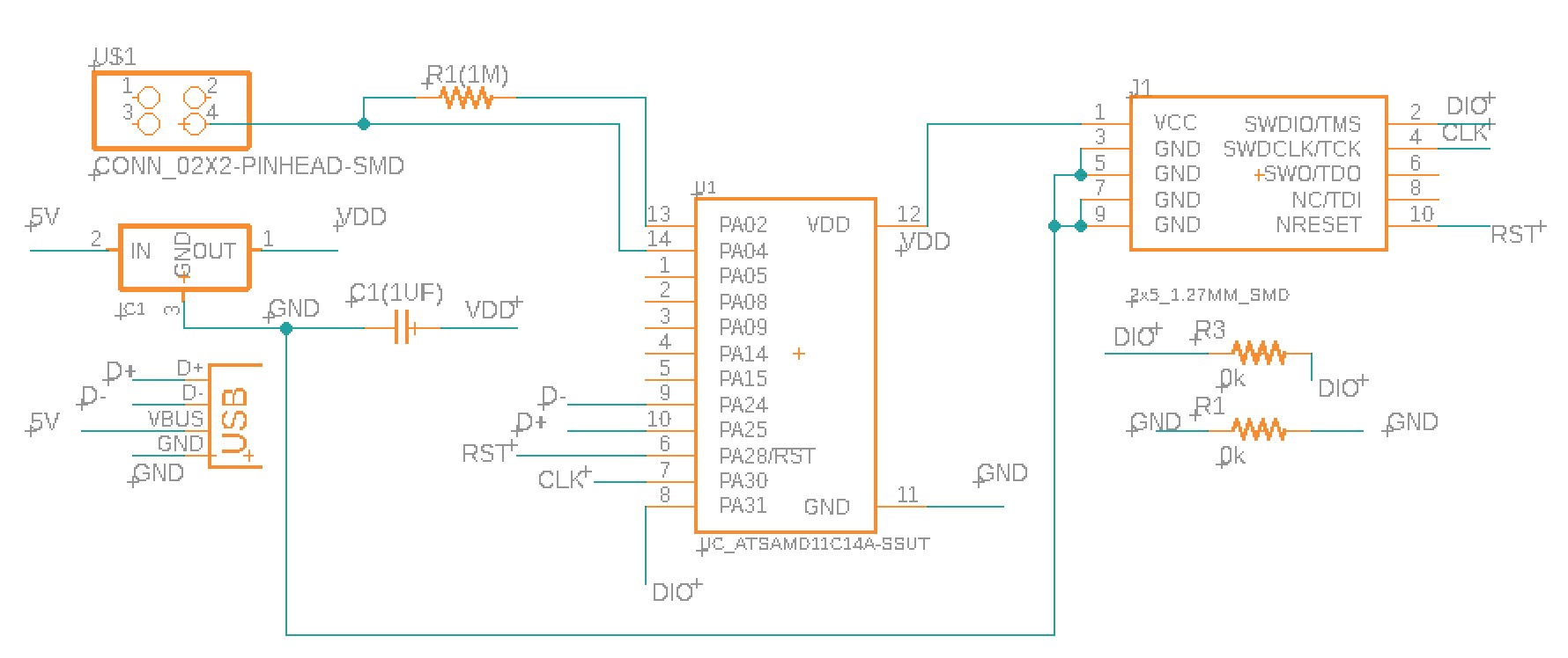
I resketched my PCB using the Eagle software. I referenced my previous PCB from week 5 and removed two LEDs, two 1k ohm resistors, and a button, and then added a 1M ohm resistor and 2 x 2 connected to make a 1pin sensor.
(The reason for using a large ohm resistor is to make the voltage at the pin steady).
I initially made a 2pin capacitor plate system, but didn't want to have 2 plates for making the car honk. Therefore, I switched to the 1-pin system. The sketch of how the 1-pin vs the 2-pin system differs using a 2 x 2 connected is shown below.
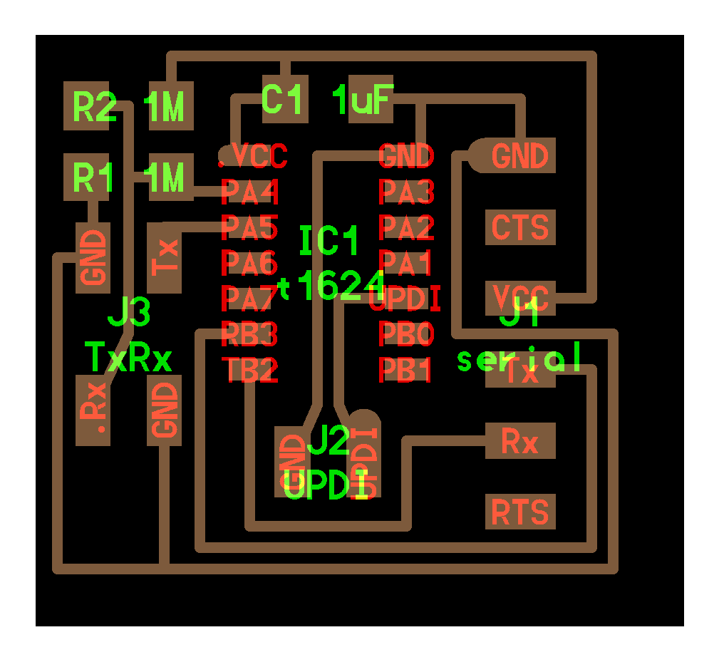
I used the template from week 5 to make my 1-pin connector PCB and redesigned the routing as shown below. I also referenced the step response board (provided via the class) to create my PCB.
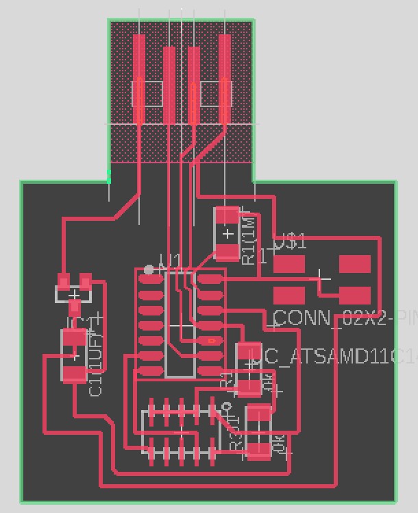
Prior to milling the board, I changed the design rule for clearance to 16mil and inspected the design. During the inspection, I noticed that some traces were too close to each other, and thus, reconnected the path.
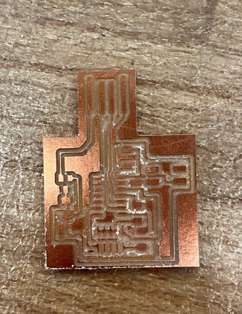
I imported .brd file from Eagle and used Othermill to print my circuit board! At this point, I became used to milling PCB because this is my 6th or 7th time making a PCB (or maybe 8th or 9th after making these mistakes...). I again used 1/32" and 1/64" bits to cut the traces.
Two of my first milling traces were torn apart... It was likely due to the loose taping of the copper board to the machine (cuts were deeply made) so I retaped the back.
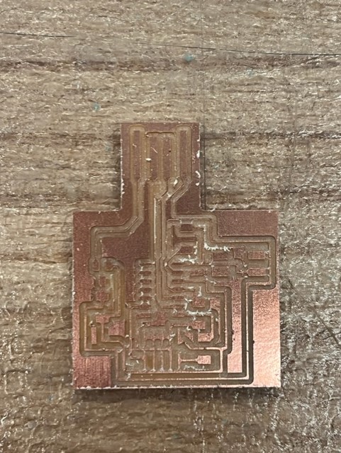
Sadly, my second milling attempt was also unsuccessful because I didn't remove all the tape and retaped the back, but rather added an additional layer of the tape. For my third attempt, I redesigned some traces and also completely retaped the back of the copper sheet.
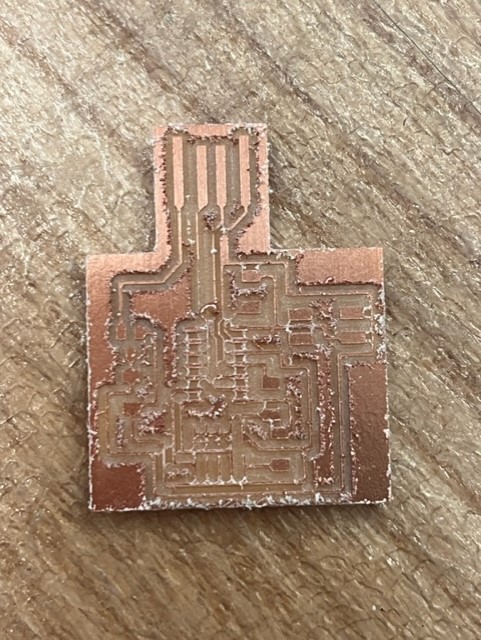
After two trials of failing PCB milling, I finally printed a good one! I hoped I did...it was not fun to make almost every mistake possible. I guess I haven't become an expert yet. This time, I used the wrong 1/32 bit: instead of the flat mill, I should have used 1/32" PCB conservative. Therefore, the traces are rough and cut unevenly.
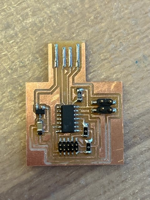
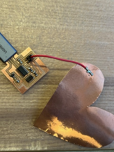
The triumph you experience when your board is finally milled properly is indescribable! I'm excited that it is finally completed :) I soldered my components to the board and prepared to program.
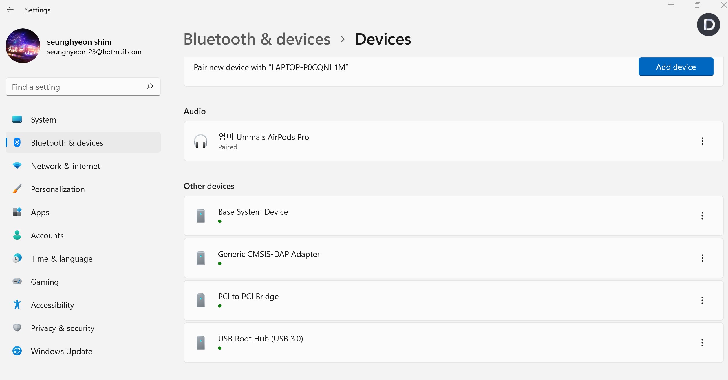
Using my previously made programmer for the Atmel SAM D11 microcontroller, I programmed my new PCB. I tried two different routes to programming my capacitor sensor (one with the support of Anthony and the other with Quentin)! The PA04 pin was used to produce the capacitor sensor readout. Then, in Arduino, a serial plotter (under the 'tool' tab) was used to monitor how voltage/ capacitor changes as the hand (acting as the other capacitor plate) moves closer or farther away from the copper plate. The graph can be understood via using the equation q=1/2*CV^2, where q = charge, C = capcitance, V = voltage.
Voltage was the readout; therefore, as the hand moves closer to the plate, the peak decreases.
Capacitance was the readout; therefore, as the hand moves closer to the plate, the graph peaks.