M8
The automated chessboard
Motivation
A few weeks ago I got a picture of my 4-year-old niece at her first chess class.
As a chess hobbyist, I was excited to see my niece taking her first steps in the world of chess, and I
couldn't wait to play with her.
Unfortunately, since I live almost 9000km away from her, playing together will be challenging. The idea of
building an automated chessboard came to my mind immediately - a board that will let two players in distant
locations have a real chess game.
"So you build a magic chessboard that moves the pieces for you?" my niece asked me over the phone. I
couldn't come up with a better description for this project.
Overview
Building the project was an incredible experience!
I enjoyed every minute I put into it and learned so much from the process - from mechanical
design to embedded programming.
After countless hours at the shop, I am extremely proud of the result, and the progress I made
while building it.
The development process can be divided into four main sections:
Each of these sections required a different set of skills and resources and combining them all
together was challenging.
I was able to achieve most of the goals I had, but there are still additional features I plan on
implementing in the near future. This page will review the development process, as well as the
plans for the future.
Mechanical design
Designing and building the hardware for the project was a lot of fun! I started by designing the
gantry
and the end effector, and then moved on to the board and the pieces.
Since I did'nt have much experience with the skill set required for this section, I think it's a
great
example of the progress I made in this class.
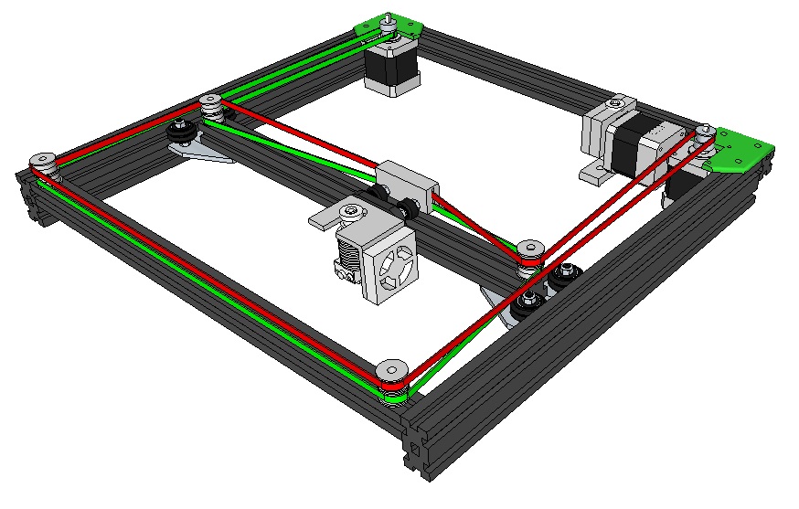
The gantry
This stage might be the one I enjoyed the most while building the project. I learned a lot about
mechanical machine design, and after many iterations, I found a gantry system that fits the needs of
the product.
I experimented with several gantry system designs before getting to the final design - most of them
are inspired by Quentin's Urumbu and Jake's Clanck.
I used a 2D core XY gantry system, powered by two stationary DC motors.
I designed the parts to fit a 25×25 millimeters Aluminum extrusion for the frame, 20×20 for the end
effector axis, and a GT2 timing belt.
I added fractures to all the moving axis mounts and designed the pieces to be smaller than the width
of the aluminum extrusion to create some pressure between the wheels and the axis.
The fractures improved the system's stability and made the movement much smoother.
The end effector contains a press-fit nut that carries the electromagnet and a timing belt fastener.
All the parts were 3D printed using a PLA printer.
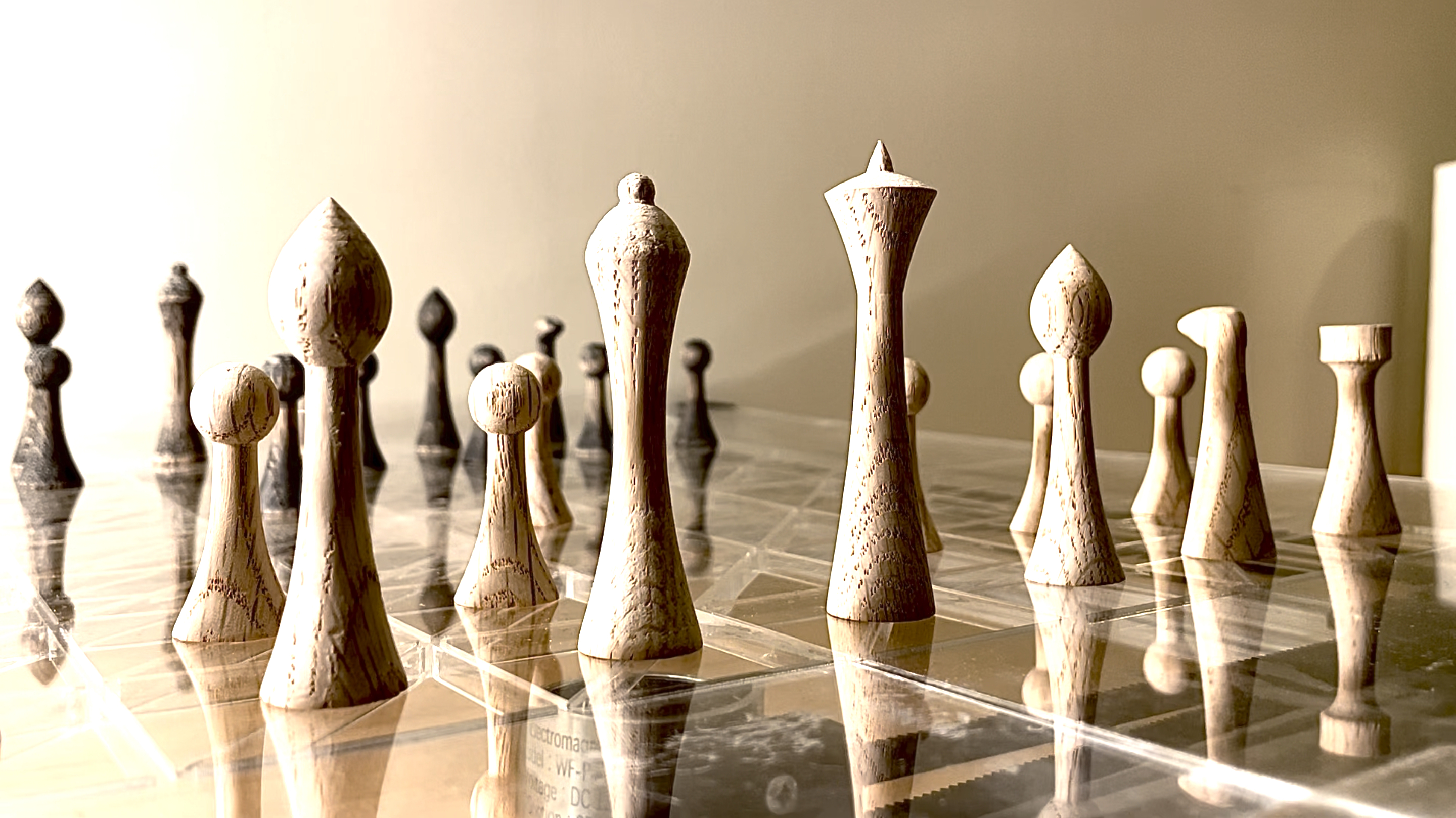
Making the pieces
Since the system is dragging the pieces over the board, I had to design a chess set with a smaller
base to allow pieces to move between the board's squares.
I aimed for a modern and simple design that fits the feel of the product.
I used a CNC lathe to carve the pieces, modified the knight and rook with hand tools, and finally
sanded everything to a smooth finish.
I colored the black pieces with a black wood stain.
Although Anthony loves to complain about this machine, the lathe we have at the shop did a wonderful
job. I really enjoyed making the pieces and by the time I finished, I got very comfortable with the
machine and would love to use it again for future projects.
The board
I used four pieces of clear acrylic to build the board, allowing the user to see everything that is
going on underneath the board.
I laser cut the triangles pattern on the thick ones to support capacitance sensors in the future.
Improvements
I want to design another version of the system that will use long linear rails instead of aluminum
extrusion. That will allow me to get a shorter gantry and get closer to the size of a regular
chessboard.
Additionally, I would love to use thin wooden boards for the chessboard to create a traditional look
and feel for the product.
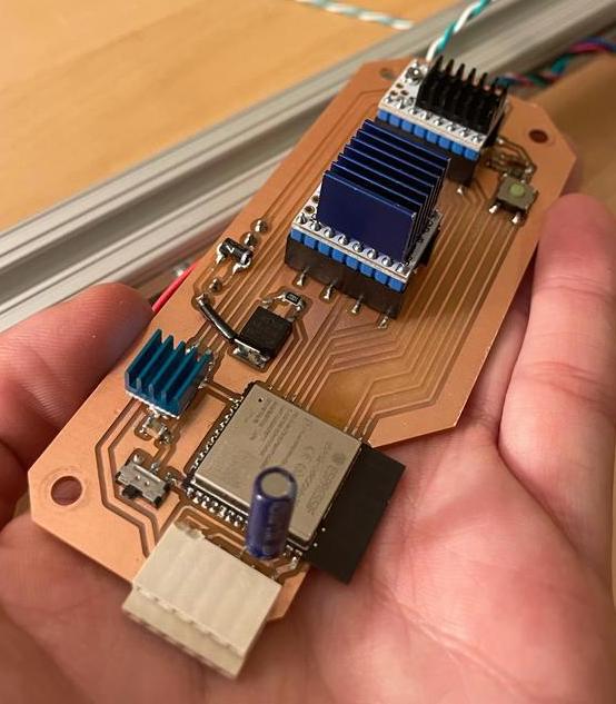
Electronics
Electronics are the heart of the project, so it was important to me to build reliable and stable
circuits.
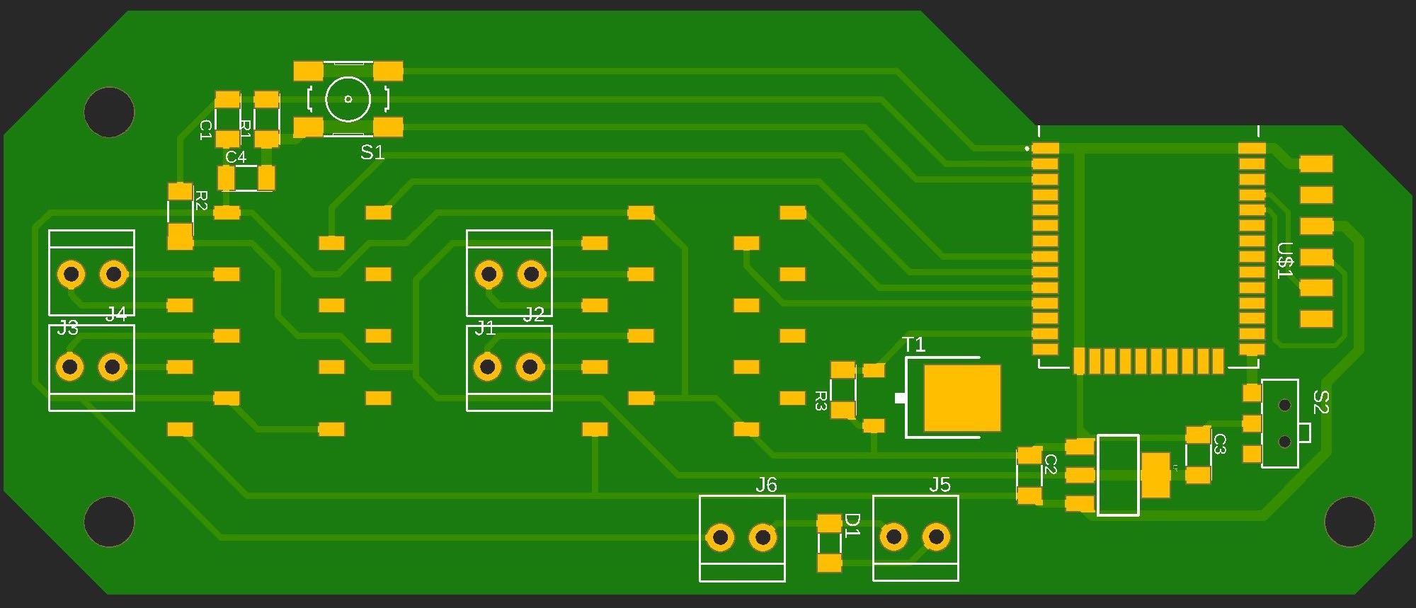
I designed the PCB based on my week 10 circuit and only added the motor drivers and routes to the
magnet.
I chose the ESP32 as a microcontroller since it allows web communication.
I used two TMC2208 drivers to drive the motors, which were easy to operate once I understood the
power consumption issues.
I also added a small N-channel MOSFET circuit and a 9V battery to control the electromagnet magnet.
Although they are far less convenient, I used more durable connectors for the wires instead of the
headers we usually use.
After experimenting with 5V and 9V power supplies, I ended up using a 12V 2Amp power supply.
Following Jake's advice, I added a large 100µF capacitor to prevent spikes in voltage.
The motor drivers and the regulator were getting hot pretty quickly at this voltage, so I placed
heat sinks on them.
I also added another FTDI connector to allow serial communication with the capacitance sensors
board.
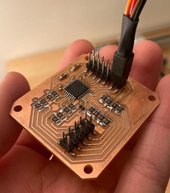
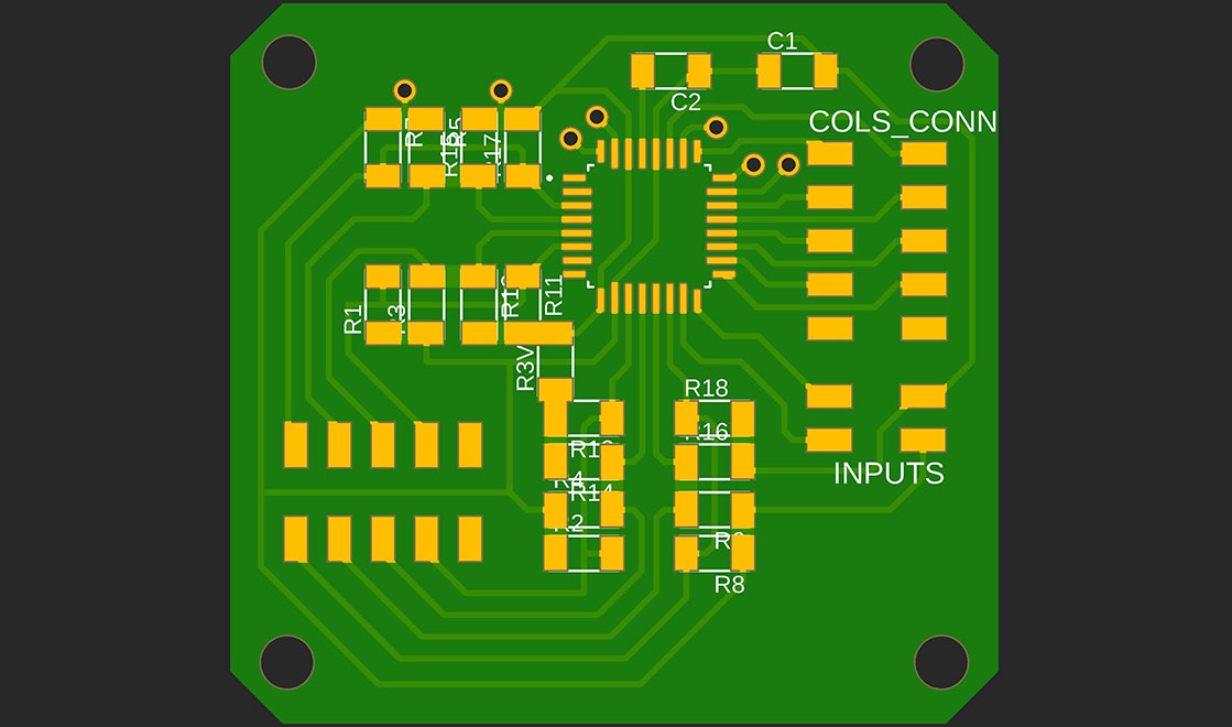
I made an additional board to manage the 64 capacitance sensors. I used SAM D21E as a
microcontroller and 16 breakout pins for the sensors.
Using this method, I was able to connect all the transmitting copper plats to the eight rows of the
chess board and the receiving plates to the columns allowing me to process data from 64 sensors with
only 16 I/O pins!
I added 3.3V, ground, and serial data pins to allow serial communication with the main ESP32 board.
Eventually, I was not able to implement the sensors system on time but still made a small POC with
nine sensors. Therefore, the PCBs I made are ready to support this function in the future, and I
will only need to cut and solder the copper plates and write the software to implement it.
Embedded programming
Writing the code for the board was the last stage of the project. I tried to create a stable system
before writing the software to simplify the development process. Those efforts paid off, and after a
short configuration of the motors' movement, I could concentrate solely on the game logic.
To make the code more organized, I wrote separate functions for each type of movement - horizontal,
vertical, diagonal, and knight.
The general code cycle starts after homing the machine. The program sends a request every half a
second to the database and looks for a new command.
If a command is received, the program will drive the motors to move the electromagnet to the current
position of the piece, turn on the electromagnet, move to the desired location, and turn the
electromagnet off.
After executing a move, the program clears the database and returns to look for new commands.
Although the code for the basic logic of the game is fully working, most of the features I plan to
implement in the future are in the software.
I managed my time to allow that since writing code is more convenient for me.
I still need to implement the knight movement, capturing pieces, and castling, as well as sending
physical moves from the board to the app after adding the capacitance sensors.
Internet communication and user interface
I did almost all of the backend and communication work during week 10 of the class.
My goal was to create a clear communication channel between the board and a web chess app to allow
sending commands from the app to the board and data from the board to the app.
Backend
I used Google's Firebase for the web app hosting and real-time database.
The first stage was to set up the environment on Firebase.
I created a real-time database that contains the current state of the board and an optional command
JSON.
The command JSON consists of the piece to move, the current location of the piece, the destination
to move it, and if the move is a capturing move.
After making a move on the app, it sends the command to the database. When the board notices a new
command, it executes the move and clears the database.
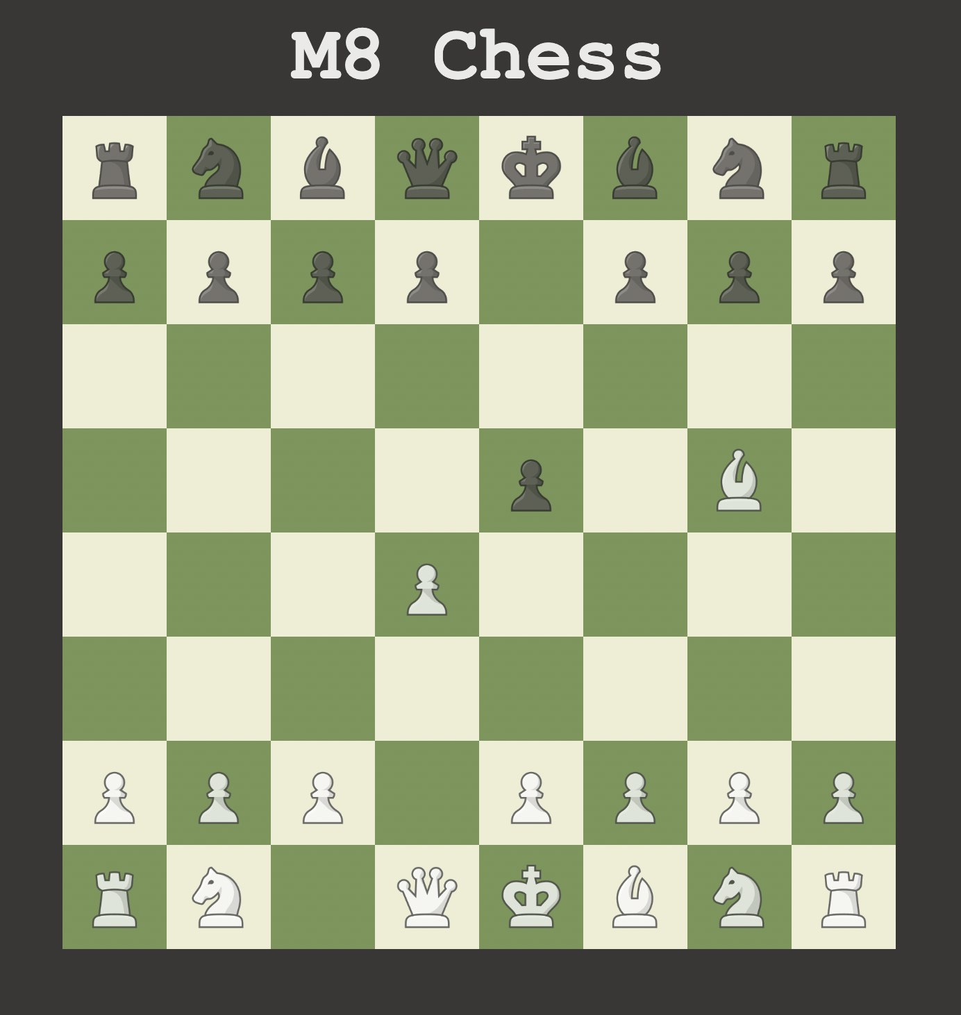
Chess web app
I created a chess web app using only Javascript and HTML that is fully playable and communicates
with the database.
I followed this tutorial to make the basic
logic, added all the Firebase communication to it, changed the UI, and fixed some bugs it had.
WiFi Manager
I added a WiFi manager system to support different networks and avoid hard-coded WiFi credentials.
After some research, I found this incredible
library that handles this burden with a few lines of code.
I had to dive into their weirdly written code to customize the interface to a more user-friendly
design, but it was worth it.
The result is a smooth, straightforward process that does not require downloading an app or any
special effort from the user.
This tutorial helped me with the
installation and configuration of the library.
Making this project was an amazing experience. I am so proud of the result and the progress I have
made while building it.
Although I did not manage to implement all the features I planned by the time of the final
presentation, I consider the project a success because it is designed to support future work.
Almost all of the future work requires coding only, without any hardware or electronics
modifications.
I designed and made (almost) anything in this project using all the different skills I
have learned in this class.
I used 3D modeling and computer-controlled cutting for the pieces, 3D printing for the gantry,
developed a web app and built the network communication process. Finally, I designed, milled, and
soldered the PCBs and wrote the embedded programming code.
Besides the materials for the pieces, I only used materials that were part of the class inventory.
Below you can find the overall estimated cost of the project.
| Part | Quantity | Price in USD |
|---|---|---|
| Oak roads | 3 | 41 |
| Black wood stain | 2 | |
| Neodymium magnets |
32 | 9 |
| Clear acrylic sheets | 4 | 30 |
| PLA filament | 30 printing hours | 30 |
| stepper motors | 2 | 20 |
| Aluminum extrusion | ~4 ft | 15 |
| TMC2208 motor drivers | 2 | 10 |
| ESP32 | 1 | 3 |
| MOSFET N-CH | 1 | 1 |
| SAM D21E | 1 | 4 |
| 12V power supply | 1 | 11 |
| 9V battery | 1 | 1 |
| Misc. electronics | 3 | |
| Total cost | 180 |