Week #1
computer-controlled cutting
Vinyl cutter
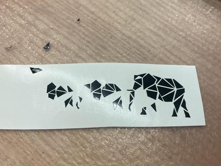
For my first assignment, I designed and cut a vinyl sticker.
After a failed attempt with an ambitiously small sticker, I've learned my lesson and designed a larger one
that came out perfect.
I used Mods to translate the designs to machine instructions.
Laser cutter
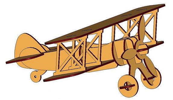
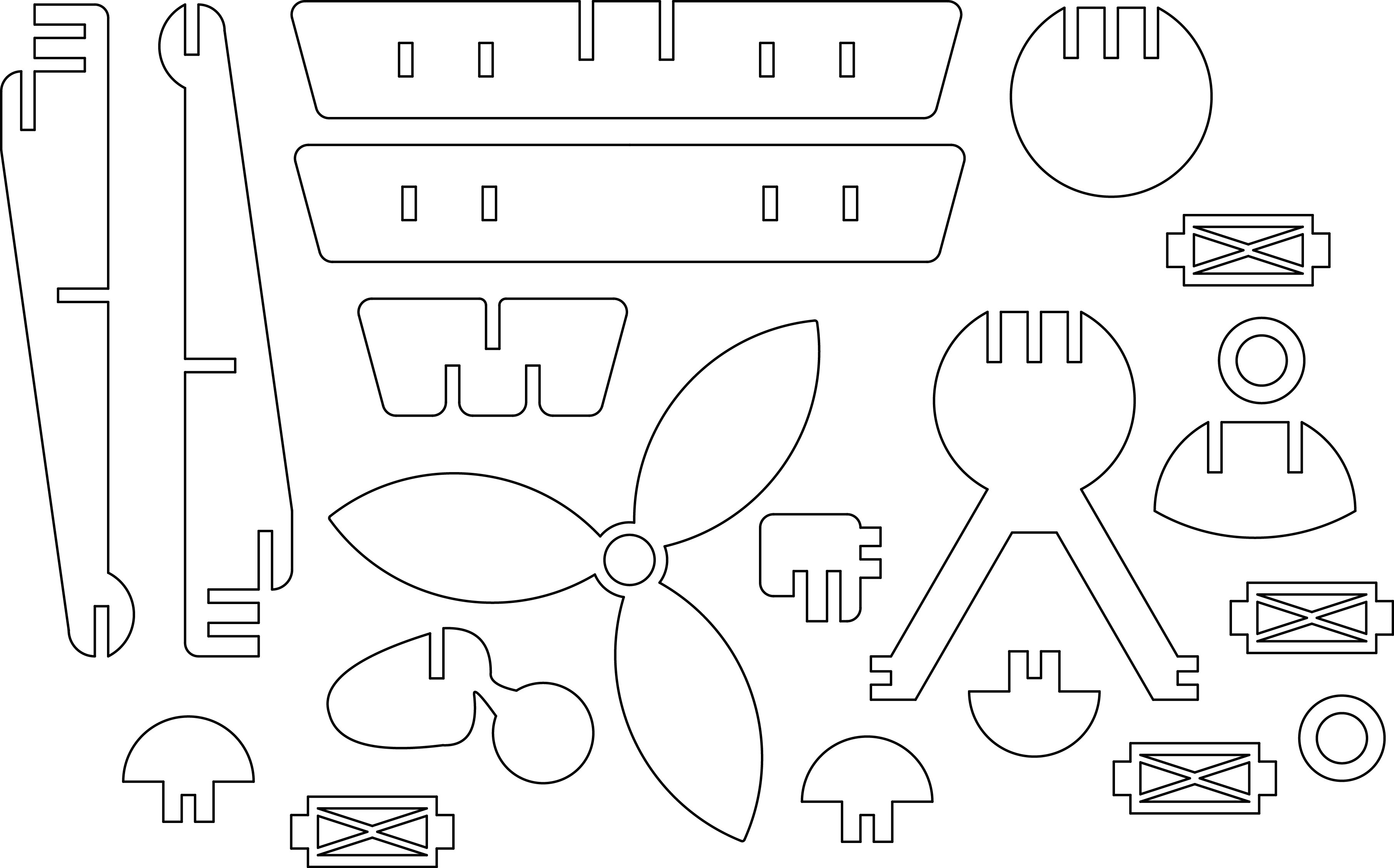
For the laser cutting assignment, I wanted to design, cut, and build an old plane model.
As a reference, I used a model I found online at
freepatternsarea.com.
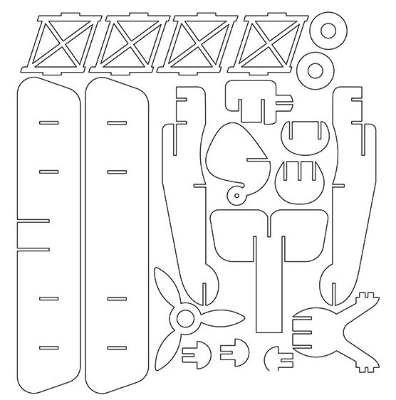
Although the reference was helpful, it still took time to design the plane since I was very careful about the
small details of the design. After getting used to the parametric design, things started to go much more smoothly,
and part by part, I finished the first draft and was ready to try it out!
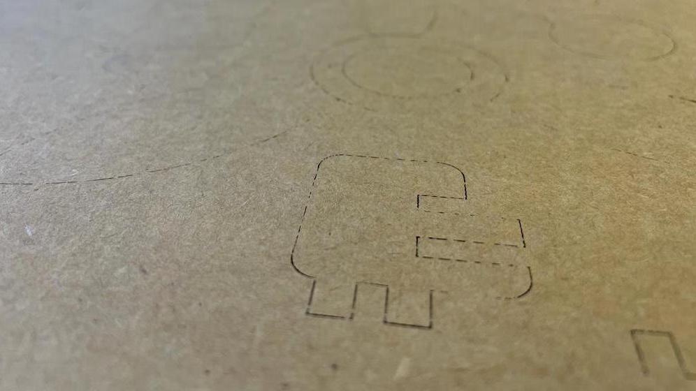
Failed attempt #1
A few seconds after I started to cut, I noticed that the cutting speed is way too slow. With help from Dave, I understood I didn't export my CAD correctly and the 3D parts were projected with multiple lines on top of each other.
Failed attempt #2
After figuring out how to export correctly, I went on and tried to cut again. This time the cutting speed was too high, creating shallow cuts that did not go al the way through the cardboard.
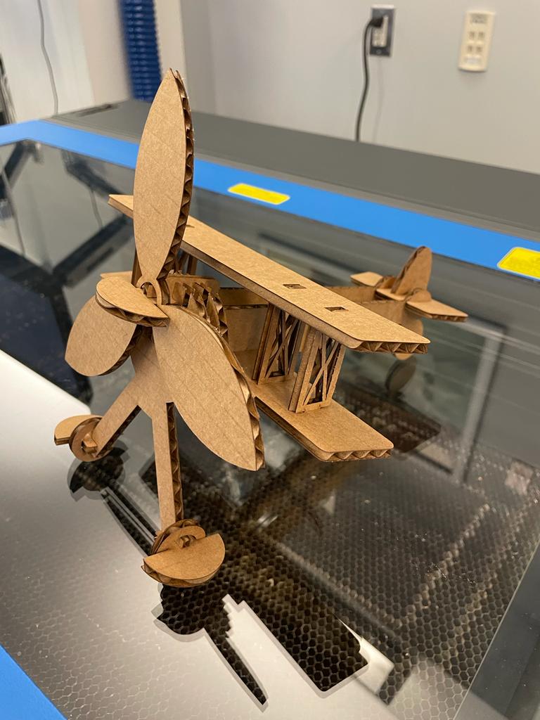
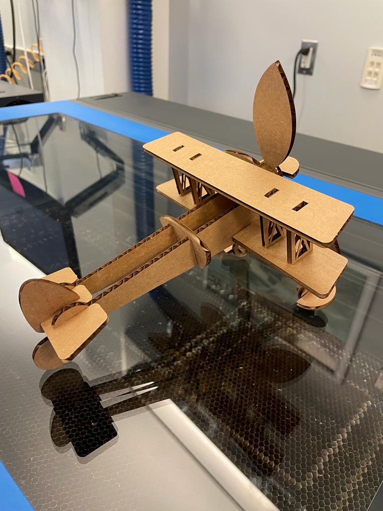
Success!
After some small tweaks, I cut the parts again and assembled everything. I was so excited that it
was successful, and many parts that I was sure will not work on the first try fit perfectly.
The overall result was beyond my expectations - the model felt robust and durable.
My main concern was the top wing as I was afraid that its joins left too much room for movement. After
asking Alfonso about that, I was already prepared with a solution but was happy to see that it was
durable and steady enough.
Design files ↓
Elephant sticker
Plane DXF file
-------
Week #2
electronics production
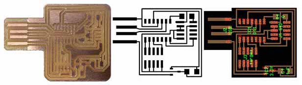
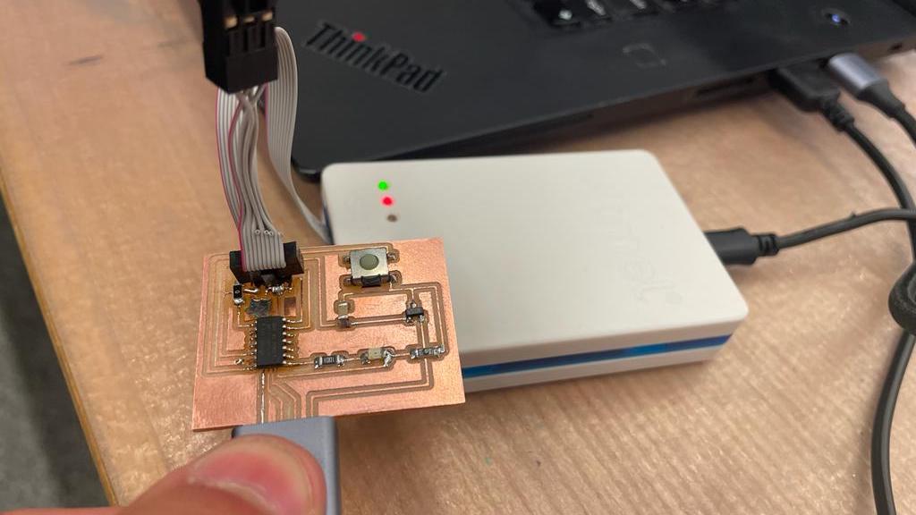
Milling the board
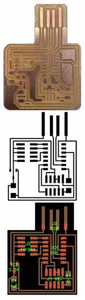
For this week we were assigned to mill, solder, and program a mil an in-circuit programmer that includes a
microcontroller. After quick training on the mill, I got into milling my board. The process was relatively
quick and did not require too much creativity. However, I did fail on my first attempt, after interfering
with the calibration process while replacing the tip.
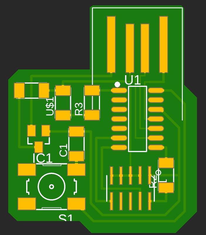
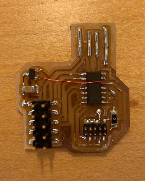
If you'll look closely you will see that the resulting board (on the left) is different than the outlines
(right and center). That is because I used a slightly different design that Anthony made.
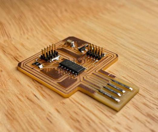
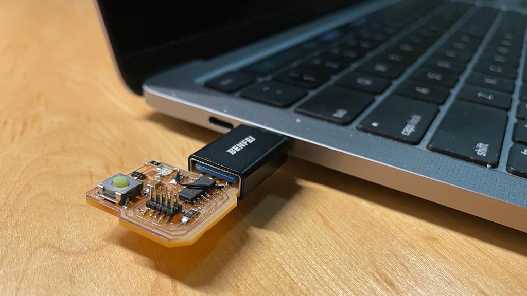
Soldering
Soldering the components was exciting since it made the board look like an actual functioning chip. I
soldered before, and after getting used to the small size of the components the process went pretty well.
I soldered two 0Ω resistors, a 1μ
capacitor, two cable connectors, and a microcontroller.
Programming the chip
Unlike the previous parts, this one was not fast and easy. Installations on an M1 MacBook are a tough
mission, and even after 2 hours of terminal commands we could'nt make it work. Both EDBG and pyOCD
refused to let me program my chip.
Eventually I gave up and used a Windows computer to program it.
-------
Week #3
3D scanning & printing
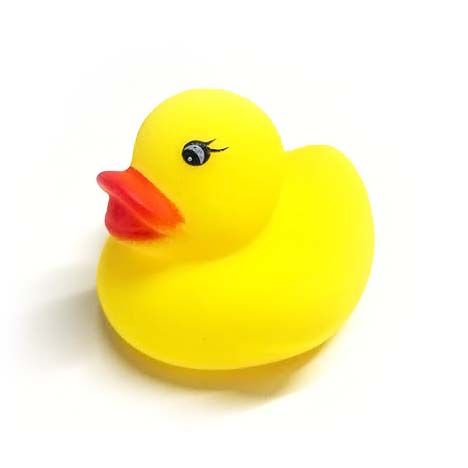
Scanning
The scanning process was way quicker then I expected. I wanted to scan a small rubber duck and used
the Revpoint scanner to do that.
I took a few tries to get it to work, but I was surprised of the results. The model that attached here is a
compressed version of the scanning which consisted of much more data, so in practice the scanner can produce
much smoother results.
Printing
3d printing always seems like magic to me. You send a 3d file and a few hours later get exactly what
you wanted. This week I realized that it's not that simple.
It took me three prints to get my original plan to work - each took several hours. Even my backup plan
wasn't successful and took two tries as well.
I assume this slow process of learning from mistakes gets faster with experience, and yet, it can be
frustrating to wait 4 hours for a print and only then understand that you need to change your design.
The mistakes I had were mostly because I didn't estimate the performance of the machines correctly
and I will elaborate on each later. I believe that my next experience with this tool will be much
smoother and I feel like Iv'e learned a lot this week.
The Lamp
For my original idea, I wanted to create a lamp that looks boring when off, but when turned on reveals
a unique shadow pattern.
It took several iterations to get the design I imagined: a web-like structure inside a seemingly
boring cylinder. A sliced version of the design is attached.
The Spinner
When my original idea ran into some problems with my original idea, I thought it can be helpful to
design a good backup model.
I wanted to print a fidget spinner in one piece since the idea of printing a functioning ball bearing
seemed exciting to me.
-------
Week #4
electronics design
Version 1
This week was less creatively challenging than most of the weeks of the class. I started by modifying the
simple SAM-D11C board and added an LED and a button.
That was the first time I used fusion to design a PCB or designed a circuit in general. It took me some time
to get used to the workflow but at the end of the week, I noticed that I felt much more comfortable with
that. I was happy to learn another complementary skill after electronics production week and I am looking
forward to embedded programming week, which will add another skill on top of these two.
After a pretty straightforward design process, I had my first version of the PCB and was ready to mill. I
milled the board and soldered the components and that whole process went smoothly without any issues.
However, programming the board was harder due to the EDBG-mac compatibility problems, but with Anthony's
help, I was able to get it programmed with the 'echo' code.
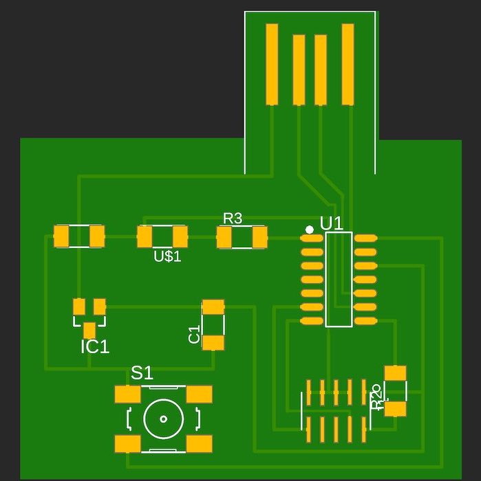
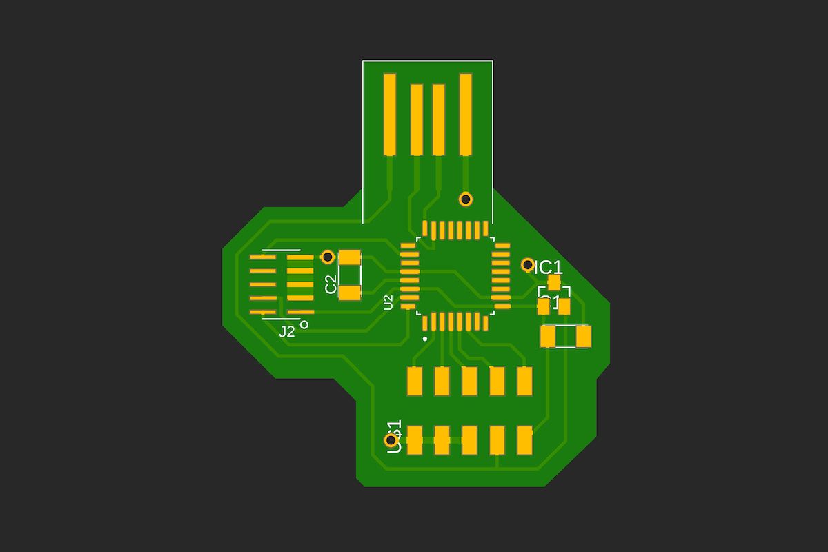
Version 2.0
After reviewing my board, I noticed that a lot of optimization can be done to significantly reduce the area
of the board and improve the arrangement of the parts.
I started tweaking my routing step by step while making sure I am not violating the design rules.
Ultimately, I got a much smaller and better-looking PCB design.
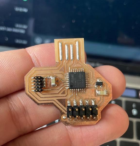
Although I had a programmed board by that point, I wanted to see if the second version is still
programmable. I milled and populated the board and went on to program it.
While trying to program it we noticed that when the board and the programmer are connected to different
power supplies, the programmer cannot find the board. Anthony suggested that this can happen due to
disconnected grounds, and indeed that was the situation.
To solve that, I added a jumper wire between the two disconnected grounds and successfully programmed the
board.
-------
Week #5
computer-controlled machining
Design
Traditional woodworking was a hobby of mine way before coming to MIT,
and so far, I have built a few
furniture pieces that I am really proud of. However, during this past week, I have learned that
computer-controlled woodworking requires different skills, and poses different issues to consider.
The idea of building a chair is sitting at the back of my mind for a long time, and I knew it will be
a
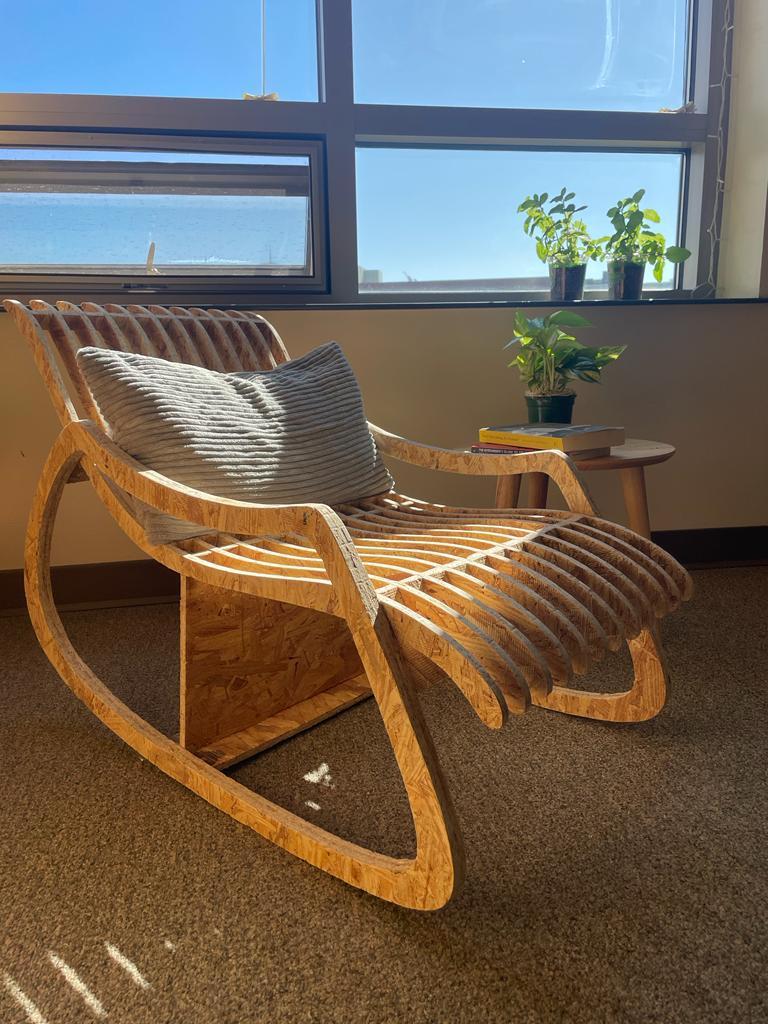
perfect fit for this week's assignment. I wanted to create a light design with curved surfaces and a
smooth appearance, that can fit different environments easily while also keeping an impressive
presence.
After sketching the legs and the 'ribs' of the chair, I added the supports and quickly had the first
version of the design.
Original design
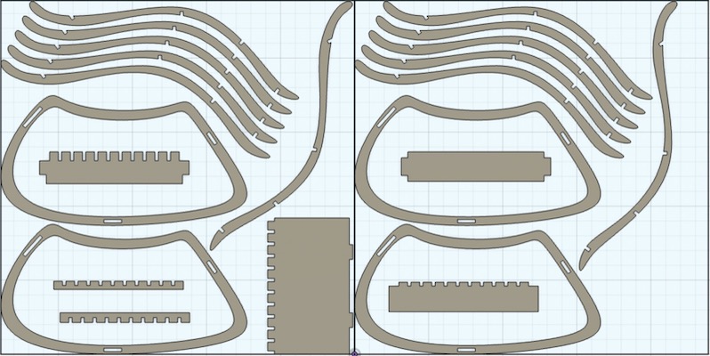
Adjustments
When I started preparing the CAM, I noticed that only cutting the ribs
will require seven
48"×48" sheets of OSB, which was much more than I could afford because of both machine time and
the amount of material.
I tried to change the design and reduce the amount of material it requires. Making it fit into two OSB
sheets while keeping the design characteristics and general appearance was an enjoyable challenge that
felt like a puzzle.
Luckily my design was relatively constrained and parametric, so updating it after most of it was
complete wasn't extremely hard.
I reduced the number of ribs from 20 to 12, increased the angle of the ribs so it'll be easier to nest
them on the sheet, and generally made all the parts smaller. After assembling the chair, I added a
support plate at the bottom to make it more robust. After many iterations, I made it fit into two
sheets but was concerned that the result will be less
stable and too small.
Final design
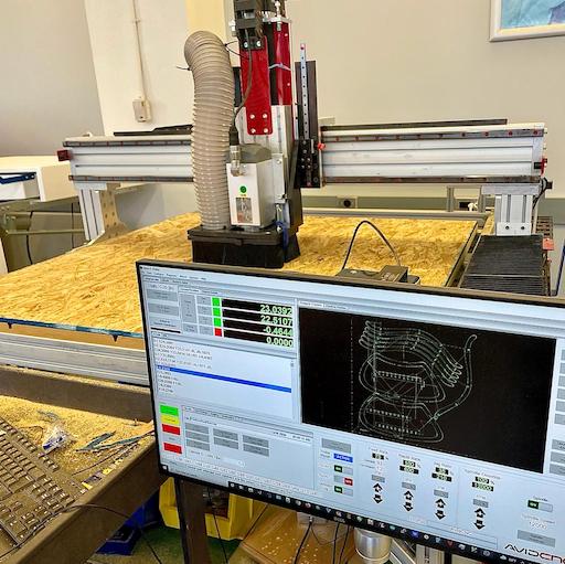
CAM & Cutting
With Anthony's great help, I was able to get the CAM done pretty quickly and had it ready to cut. We
added 'dog bones' to all the ribs joints but left the legs as designed to get a cleaner look at the more
exposed joints.
The cutting process was surprisingly fast and took less than 15 minutes.
However, removing the pieces from the machine bed was a lot more challenging. Since some of them were
pretty thin and fragile on their own, it required us to be extra careful and we still broke one of the
ribs.
Anthony was able to extract the second sheet as a whole and saved us the trouble of extracting each
piece individually. Later we cut a few more ribs from scrap pieces to replace the broken ones.
I think that was the most challenging and stressful part of this job and I felt a huge relief when we
were done with it.
I got plenty of help from Anthony throughout the week and especially during this part, and I thank him
a
lot for that.
Assembly & Finish
The assembly process felt more similar to the woodworking experience I had before. It allowed me to
get a better understanding of the material and its behavior and also get some important conclusions
about my design.
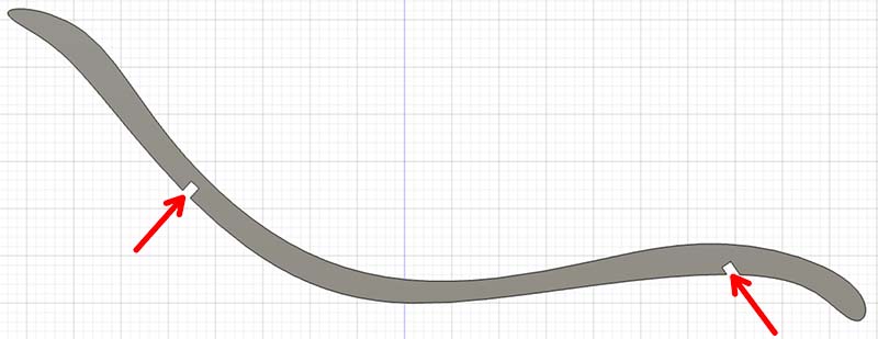
I started with gluing the legs, then assembled the supports, and finally attached the ribs. As can be
seen in the attached sketch, the main problem I found during the assembly was that I designed the ribs
in a way that the top and bottom joints go in opposite directions.
Because of that, attaching the ribs required putting heavy pressure on them, and since they were
pretty fragile, a few broke during this process.
To solve that I used a rasp to file the bottom joint of each rib so it will be easier to insert them.
Finally, I added the support pieces to the ribs and started with finishing.
Before starting the project, I liked the idea of fine finishing an OSB product and found the examples
we saw in class very impressive. Throughout the week, my attitude towards OSB changed, and I
understood such a finish will require equipment and time I did not have.
I invested a decent amount of time in sending and used some wood-filler (sawdust and glue) to hide
some of the defects in the material.
Although the finish is far from perfect, the result is relatively smooth, with no sharp edges and no
chips.
Conclusions
-
Overall I am very proud of the final product, especially with the limitations I had. I am particularly
happy
that I tried to come up with creative solutions to those challenges, rather than escaping to methods
that I am more comfortable with like adding material or more traditional woodworking.
- Consider the robustness of each part before assembly rather than the robustness of the final
product alone.
I was relatively confident that my design is strong enough but had a hard time removing and assembling the ribs that I did not expect. - Learn the material better! Despite Anthony's warnings, I overestimated the material durability, making the cutting and assembling process much more challenging, and the final product not as robust as I expected.
- Consider the assembly while designing. It is important to notice that the design will allow a convenient assembly to avoid issues like the opposite directions joints I mentioned above.
Throughout the week, I've noticed a couple of issues with my design that if addressed correctly, could save me a lot of time.
Design files ↓
Original DesignFinal Design
-------
Week #6
embedded programming
Overview
That was one of the most exciting weeks for me in the class so far. I felt like I learned a lot and was very proud
of the results I got at the end of it.
I wanted to build a programmed circuit that will interact with an addressable LED strip to create a game for two
players.
Originally I thought of a digital tug-of-war game, in which each player presses a button to push their
opponent backward.
Unfortunately, due to time constraints, I had to simplify my goals to complete the
assignment on time, and my idea was to design a board that in the future will support more advanced programs, but in
the meantime, will carry a simpler one.
Making The Board
I started my design from the basic SAM-D11C microcontroller circuit and only added a 10-pin connector,
connected to different I/Os, ground, and 5V.
The design was simple but very flexible and can be used for all sorts of tasks depending on the program
and the components that are connected to it.
I finished the design, milled, and soldered, and was finally ready to start working on the program! Little
did I know that the software library I was planning to use (Adafruit Neopixel) refuses to work with the
SAM-D11C and requires stronger microcontrollers. Junhong tried to help me modify the library system files
and force it to support the SAM-D11C, and I found
this website that described the same problem, but we quickly understood that milling a new board
with a different microcontroller will be quicker and easier.
I modified my design and used the SAM-D21E, which is supported by Adafruit Neopixel and many other libraries. I also
connected the empty pins on the connector to two additional I/Os and one 3.3V that may be useful in the future.
Soldering the SAM-D21E is much more challenging than other components I've used so far, but the practice during the
past electronics weeks paid off and everything went as planned. This time I knew that I am done with building the
board and only left with writing the program.
Programming
I started by loading the Adafruit
Neopixel example code to verify my board functions correctly.
It was exciting to see the LEDs working and it felt like I finally completed this skill set of
designing a board, building it, and programming it.
Additionally, I was able to properly install EDBG after having the common installation problems on
mac. To do this I carefully followed the instructions on this website.
Writing The Code
I was less worried about this part of the week and playing with the code and LEDs was fun. I wanted to
write a program that takes input from a button and sends 'pulses' through the LEDs strip.
I used an array of 10 integers, each of which can function as an indicator of the starting point of a
pulse.
Each button press will take the first array argument that still does not represent a pulse and start
incrementing it on each loop iteration. This allows me to have multiple pulses at the same time instead of
one.
Additionally, I added a feature that stacks all pulses at the end of the strip until the whole strip
is full, Then changes the color and sends a new pulse.
While presenting my board in class I noted that I had a bug in my software that cause the pulses to
slow down if multiple pulses were sent. Thanks to Raiphy we were
able to perform real-time debugging and fix the issue during the break.
I also laser-cut an acrylic enclosure to make it feel more like a finished product.
I added some additional features, including another button that turns all the
lights on instead of sending pulses and a long press to turn the LEDs off.
#include <Adafruit_NeoPixel.h>

#ifdef __AVR__#include <avr/power.h>
#endif
#define LEDPIN 3
#define BTN1 1
#define BTN2 2
#define NUMPIXELS 300

Adafruit_NeoPixel pixels(NUMPIXELS, LEDPIN, NEO_GRB + NEO_KHZ800);
#define DELAYVAL 0
#define NUMPULSES 10
#define PW 10

int x[] = { -1, -1, -1, -1, -1, -1, -1, -1, -1, -1};

int buttonState = 0;
int k = NUMPIXELS + PW;
int R = random(0, 100);
int G = random(0, 100);
int B = random(0, 100);

void setup() {

#if defined(__AVR_ATtiny85__) && (F_CPU == 16000000)
  clock_prescale_set(clock_div_1);
#endif

  pixels.begin();
  pinMode(BTN1, INPUT_PULLUP);
  pinMode(BTN2, INPUT_PULLUP);
  pixels.clear();
  pixels.show();
}

void loop() {
  if (digitalRead(BTN2) == LOW) {
    int c = 0;
    while (digitalRead(BTN2) == LOW) {
      if (c >= 100) {
        pixels.clear();
        pixels.show();
      }
      delay(10);
      c++;
    }
    if (c < 100) {
      for (int i = 0; i < NUMPIXELS; i++) {
        pixels.setPixelColor(i, pixels.Color(R, G, B));
      }
    }
    k = NUMPIXELS + PW;
    pixels.show();
    R = random(0, 100);
    G = random(0, 100);
    B = random(0, 100);

  }

  if (digitalRead(BTN1) == LOW) {
    while (digitalRead(BTN1) == LOW) {
      delay(10);
    }
    for (int p = 0; p < NUMPULSES; p++) {
      if (x[p] == -1) {
        x[p] = 0;
        break;
      }
    }
  }

  for (int i = 0; i < NUMPULSES; i++) {
    if (x[i] != -1) {
      pixels.setPixelColor(x[i], pixels.Color(R, G, B));
      pixels.setPixelColor(x[i] - PW, pixels.Color(0, 0, 0));
      if (x[i] < k) {
        x[i]++;
      } else {
        x[i] = -1;
        k = k - PW;
      }
    }
  }
  delay(DELAYVAL);
  pixels.show();

  if (k < PW) {
    k = NUMPIXELS + PW;
    R = random(0, 100);
    G = random(0, 100);
    B = random(0, 100);
  }
}
-------
Week #7
molding & casting
Overview
This was one of the hardest weeks for me in the class so far.
Although I started working on the assignment early in the week, I experienced many troubles with my molds
and was able to start casting only the night before class.
After all, I am relatively proud of the result and happy that I could finish on time, considering the
circumstances.
Design
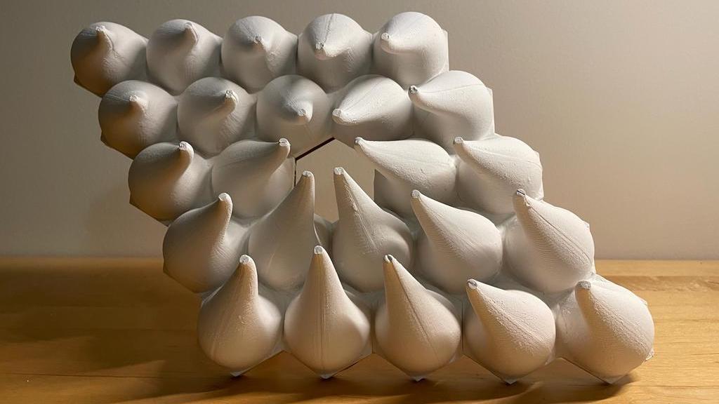
My goal was to design a product that will utilize the main advantage of molding and casting - to produce
many identical parts quickly.
I remembered seeing a kind of sculpture online that uses many similar 3D printed parts to create an art piece with a "flowing"
impression.
I thought I can produce a simple version of a sculpture as such using molding and casting.
I started by designing a sigle part, which was pretty simple using the Form tool on Fusion. Then with the
assembly feature, I design a final version of the assembled sculpture.
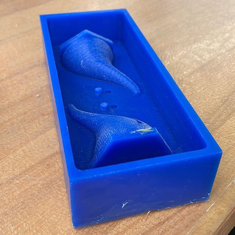
Mold Design
To derive the design of the mold from the final part shape, I sliced each part in half and placed the
halves in a hollow box of the size we used for machining.
I added pegs that will allow me to assemble the molds accurately and was ready for machining.
This part proved to be crucial later in the week, and the mistakes I've made here cost me a lot of
time.
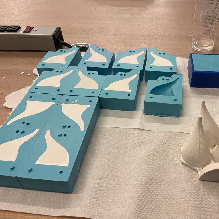
It seemed perfectly okay to have one type of mold for each part, and I was sure that producing two
identical molds will allow me to assemble a full part.
After casting two silicon molds I found out that I was completely wrong and forgot to consider the
need for mirrored molds for parts that are not fully symmetric.
Eventually, I had two perfect molds that can only produce the left half of my parts.
I accepted the fact that I need to machine a mirrored version of the mold. It was especially discouraging
due to the scarcity of machine time.
Eventually, I machined a mirrored version of my mold, but due to a mismatch od the pegs I had to cast
the parts in halves and glue them.
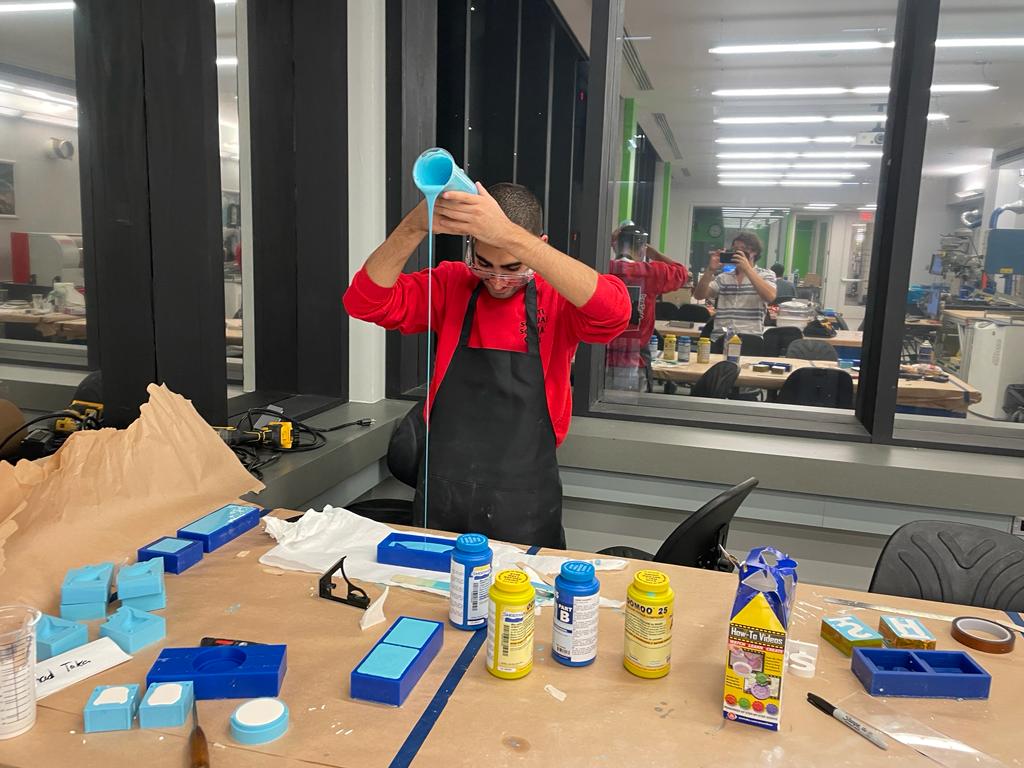
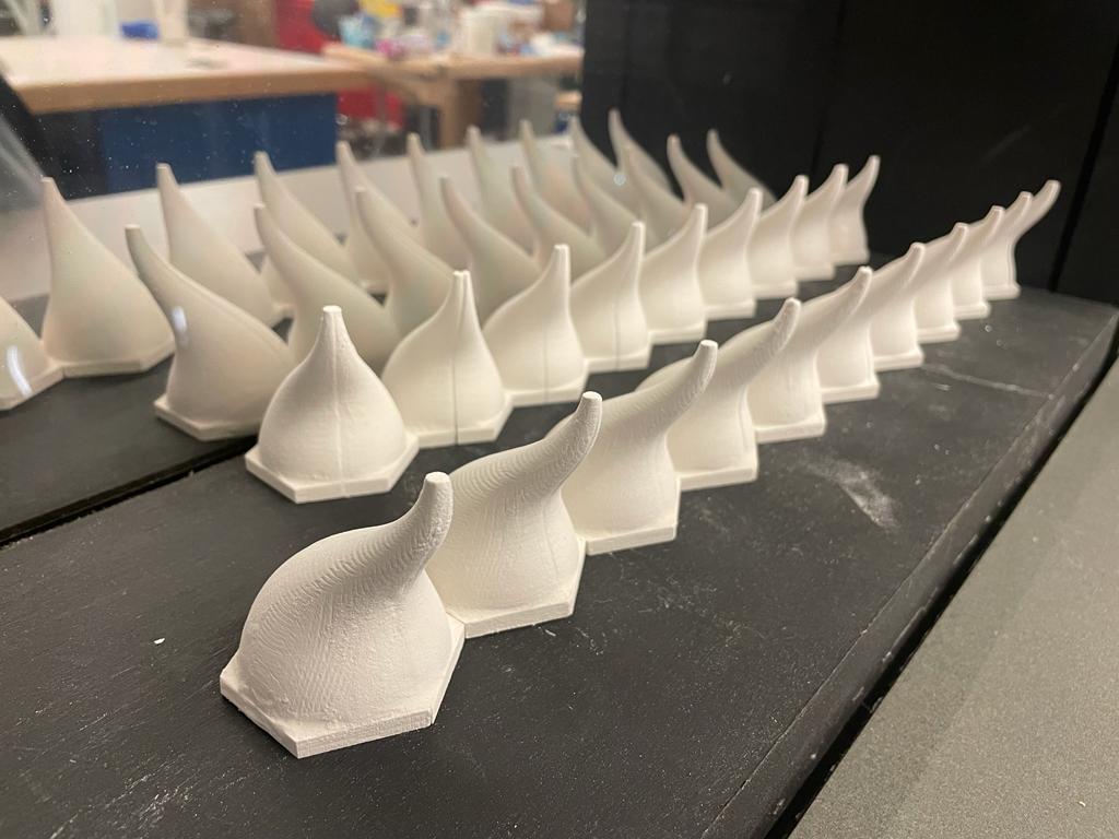
Machining & Casting
After fixing the issues with the molds I could start producing the parts. From this point, things went
much more smoothly and I was able to make the parts pretty quickly and efficiently.
I used Oomoo to make the molds and dry stone to make the parts. The casting process was pretty
straightforward and I enjoyed it a lot.
I used diluted dry stone to glue the pieces and to smooth the surface after gluing.
-------
Week #8
input devices
Overview
I had a lot of fun working on this week's project, and although there is some more work to be done, I am very proud
of the result.
My goal for the week was to use a sensor measurement to synthesize music.
After the lecture, I was curious to work with the optical distance sensors (VL53L0X \ VL53L1X) since they seemed
relatively simple to use while still producing measurements with impressive accuracy and range.
My idea was to build a rotating platform and place the sensor in front of it. That way, by placing an object on the
platform, the distance measurement will change periodically, creating a different melody for different objects.
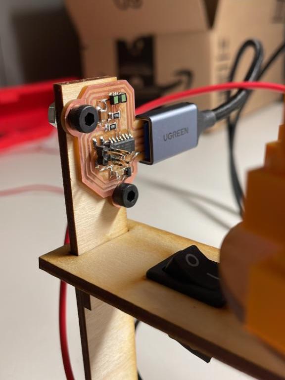
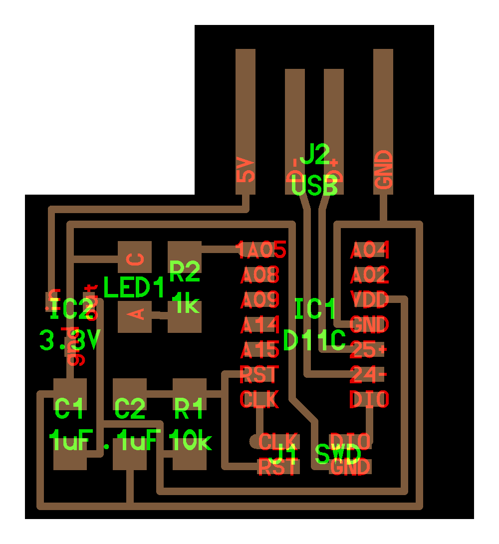
Making The Board
I used Neil's board as a reference and only changed some of the routings. That time, I didn't plan to use the board to do anything except measure distance, and unfortunately didn't add breakout pins. Because of that, I had to solder many wires to connect the speaker.
Soldering
That was the first time I used the soldering paste, and I am glad it worked on the first try. I found a lot
of uncertainty in this process since it is almost impossible to know if the component was correctly placed
or well-soldered.
Even after soldering the sensor, there is no way to tell if it's appropriately connected until programming
the circuit.
Enclosure
To build the enclosure, I laser-cut the parts from wood and glued them all together. I aimed for a more
refined design, yet the result was good and held everything together without too many visible wires. I used
a DC motor with a gearbox that was wired to a potentiometer, a switch, and a 9V battery. The motor circuit
was completely separate from the sensor board.
When assembling, I tried to use reliable connections, including heat shrinks for the electronics or
designated grooves and holes for mechanical connections.
Programming
I started by loading the example code from Pololu's
VL53L1X library.
At this point, I still didn't know if I properly soldered the sensor and was curious to test it.
Immediately after loading the software, the measurements started to go through the serial plotter!
It was an exciting moment that solved the uncertainty about the board.
Making Music
The result was noisy and not very pleasant, but it was great for a start.
I added discretization to the sensor output and associated each relevant distance range with a note's frequency in the A Minor scale.
Lastly, to address the noisiness of the sensor output, I added a moving average filter that computes the
average value of the last five measurements.
Together with lowering the motor speed, this step dramatically improved the overall outcome.
Required improvements
Although the main board works well, I used too many patches to hide some significant problems. Most of them are tightly related to output devices, so I hope to solve them during output devices week! These are the main issues I need to address:
- Unstable microcontroller startup - every time the board wakes up, it takes a few resets until it gets stable. I temporarily connected a button to the reset pin of the board, and every time I connected the board, I kept resetting it until it started working. Neil suggested a small addition to the board (can be found here) that slows down the start-up process and allows the board to stabilize.
- A separate circuit for the motor - I used a separate 9V circuit for the motor and controlled its speed using a 200-ohm trimpot. This method dissipates a lot of energy and adds unnecessary components to the product. For next week, I will power the motor through the board and control it through the microcontroller.
- Low speaker volume - The amplification circuit Junhong helped me to assemble was good as a patch, but I am sure that with proper connections and a better speaker, I can get better results.
-------
Week #9
output devices
Light Pong
For this week, I used my board from embedded programming week and wrote a different program to use the
addressable LEDs to make a ping pong game!
Due to the flexibility of the board, it didn't require any hardware changes and was fairly easy to
implement. I think this is a great example of the flexibility that comes with embedded programming.
I was extremely happy with the result and had a lot of fun making it and playing with it.
#include <Adafruit_NeoPixel.h>

#ifdef __AVR__#include <avr/power.h>
#endif

#define LEDPIN 3
#define BTN1 1
#define BTN2 2
#define NUMPIXELS 100

Adafruit_NeoPixel pixels(NUMPIXELS, LEDPIN, NEO_GRB + NEO_KHZ800);

int button = 0;
int button_p = 0;
int button1 = 0;
int button2 = 0;
int button1_p = 0;
int button2_p = 0;
int ball = 0;
bool gameOn = false;

int R_player1 = 60;
int G_player1 = 8;
int B_player1 = 0;

int R_player2 = 23;
int G_player2 = 60;
int B_player2 = 1;

int R = 200;
int G = 200;
int B = 200;

void setup() {
    #if defined(__AVR_ATtiny85__) && (F_CPU == 16000000)
    clock_prescale_set(clock_div_1);
    #endif
    pinMode(BTN1, INPUT_PULLUP);
    pinMode(BTN2, INPUT_PULLUP);
    pixels.begin();

    pixels.clear();
    pixels.show();
    }

    void loop() {
    // new game starts
    int dir = random(0, 2);
    int DELAYVAL = 3500 / NUMPIXELS;

    pixels.clear();
    for (int i = 0; i <= NUMPIXELS / 4; i++) {
        pixels.setPixelColor(i, pixels.Color(R_player1, G_player1, B_player1));
    }
    for (int i = NUMPIXELS - 1 - NUMPIXELS / 4; i <= NUMPIXELS - 1; i++) {
        pixels.setPixelColor(i, pixels.Color(R_player2, G_player2, B_player2));
    }

    if (dir == 1) {
        ball = 0;
    } else {
        dir = -1;
        ball = NUMPIXELS - 1;
    }

    pixels.setPixelColor(ball, pixels.Color(R, G, B));
    pixels.show();

    while (not gameOn) {
        if (dir == -1) {
        button = digitalRead(BTN2);
        } else {
        button = digitalRead(BTN1);
        }
        if (button == LOW) {
        gameOn = true;
        ball += dir;
        }
    }

    while (gameOn) {
        button1_p = button1;
        button2_p = button2;
        button2 = digitalRead(BTN2);
        button1 = digitalRead(BTN1);

        if (dir == 1) {
        if (ball > (NUMPIXELS - NUMPIXELS / 4) - 2) {
            button = button2;
            button_p = button2_p;
        } else {
            button = HIGH;
        }
        } else {
        if (ball < NUMPIXELS / 4 + 1) {
            button = button1;
            button_p = button1_p;
        } else {
            button = HIGH;
        }
        }
        if (button == LOW && button_p == HIGH) {
        dir *= -1;
        ball += 2 * dir;
        if (DELAYVAL > 200); {
            DELAYVAL *= 0.95;
        }
        }

        delay(DELAYVAL);
        if (ball == 0) {
        gameOn = false;
        for (int i = 0; i < NUMPIXELS / 2; i++) {
            pixels.setPixelColor(i, pixels.Color(100, 0, 0));
            pixels.setPixelColor(i + (NUMPIXELS / 2), pixels.Color(0, 100, 0));
        }
        pixels.show();
        delay(3000);
        } else if (ball == NUMPIXELS - 1) {
        gameOn = false;
        for (int i = NUMPIXELS / 2; i < NUMPIXELS; i++) {
            pixels.setPixelColor(i, pixels.Color(100, 0, 0));
            pixels.setPixelColor(i - (NUMPIXELS / 2), pixels.Color(0, 100, 0));
        }
        pixels.show();
        delay(3000);
        }
        else {
        pixels.setPixelColor(ball - dir, pixels.Color(0, 0, 0));
        for (int i = 0; i <= NUMPIXELS / 4; i++) {
            pixels.setPixelColor(i, pixels.Color(R_player1, G_player1, B_player1));
        }
        for (int i = NUMPIXELS - 1 - NUMPIXELS / 4; i <= NUMPIXELS - 1; i++) {
            pixels.setPixelColor(i, pixels.Color(R_player2, G_player2, B_player2));
        }
        pixels.setPixelColor(ball, pixels.Color(R, G, B));

        ball += dir;
        pixels.show();
        }
    }
}
-------
Week #10
networking & communications
Overview
This week was a great opportunity to start working on my final project.
I wanted to start building the infrastructure for my chessboard project and aimed to create a board that
handles network communication.
My goal was to be able to control the I/O pins of the microcontroller from a distant platform.
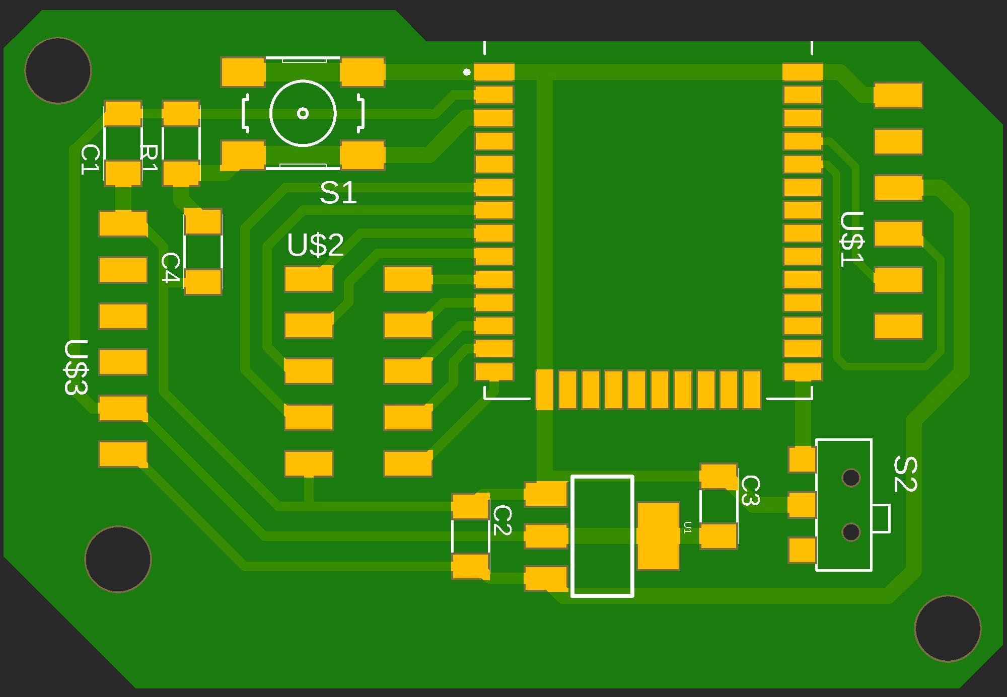
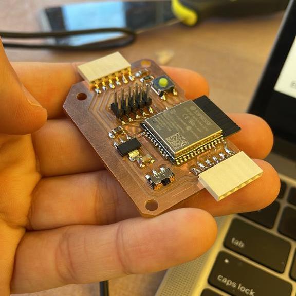
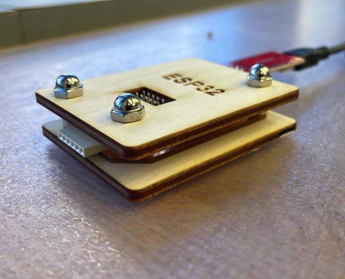
Boards
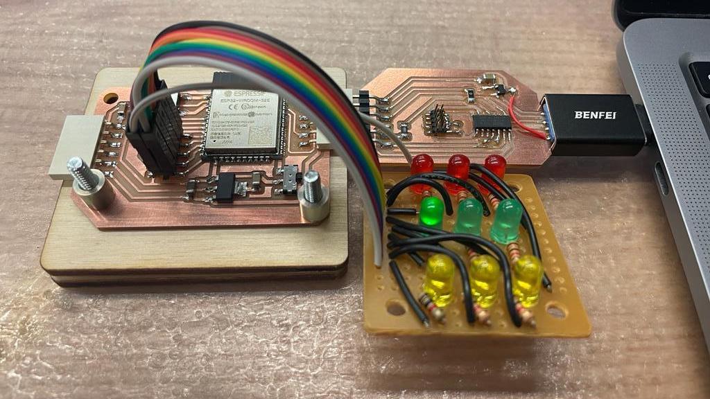
I used Neil's example board as a reference and added some breakout pins for some GPIOs. Since this was only
a development board, I did not use all the GPIOs of the ESP32.
Milling and soldering were pretty straightforward.
Reset problem
I had a similar problem as I had with my input devices board. The ESP was resetting very frequently and was
not stable at all.
With Junhong's help, we found that the problem was that the rise time after a reset was too short, not
allowing enough time for the board to stabilize. Junhong suggested an easy fix - adding a capacitor between
the reset button and the ground.
I soldered the capacitor as a patch, which immediately solved the problem.
Later I accidentally ripped the reset button and some of the copper around it, so I updated my design and
remade the board.
I also used a breadboard to build a simple LED board for testing and laser cut an enclosure.
The FTDI Programmer
Due to the scarcity of FTDI cables in the shop, I used Quentin's design and built an FTDI programmer
board.
I've been using it as my only programmer for a few days, and it's working perfectly.
Software
After having some positive experiences with it, I decided to use Google's Firebase as a backend service for this week and my final project. Although Firebase saves a lot of the burden, there was still a lot of software work to set up the environment and eventually create stable communication between the ESP to a web app.
The ESP side
I followed this great
tutorial to set up the basic connection between my firebase project and the ESP.
Generally,
I created a firebase project and configured a real-time database, which easily allowed to read and write
data from different clients.
After that, I used a firebase-to-ESP32 library to build test programs that either read or write data
from the database.
Eventually, I wrote a program that allowed me to control several LEDs by changing database values.
The code is repetitive and messy since it is only for testing.
#include
#if defined(ESP32)
#include
#elif defined(ESP8266)
#include
#endif
#include
#include

// Provide the token generation process info.
#include "addons/TokenHelper.h"
// Provide the RTDB payload printing info and other helper functions.
#include "addons/RTDBHelper.h"

// Insert Firebase project API Key
#define API_KEY "AIzaSyB-fTzPgR0OgoQQ39NwGTsnaVDQ-6AWDKM"

// Insert RTDB URLefine the RTDB URL */
#define DATABASE_URL "https://m8-chess-default-rtdb.firebaseio.com/"

// Define Firebase Data object
FirebaseData fbdo;

FirebaseAuth auth;
FirebaseConfig config;

#define LED_PIN_0 25
#define LED_PIN_1 26
#define LED_PIN_2 27
#define LED_PIN_3 14
#define LED_PIN_4 12
#define LED_PIN_5 32
#define LED_PIN_6 33

unsigned long sendDataPrevMillis = 0;
int LED0;
int LED1;
int LED2;
int LED3;
int LED4;
int LED5;
int LED6;

float floatValue;
bool signupOK = false;

void setup()
{
    Serial.begin(115200);

    WiFiManager wm;

    wm.resetSettings();

    bool res;
    res = wm.autoConnect("M8_Chessboard", "");

    if (!res)
    {
    Serial.println("Failed to connect");
    }

    Serial.print("Connecting to Wi-Fi");
    while (WiFi.status() != WL_CONNECTED)
    {
    Serial.print(".");
    delay(300);
    }
    Serial.println();
    Serial.print("Connected with IP: ");
    Serial.println(WiFi.localIP());
    Serial.println();

    /* Assign the api key (required) */
    config.api_key = API_KEY;

    /* Assign the RTDB URL (required) */
    config.database_url = DATABASE_URL;

    /* Sign up */
    if (Firebase.signUp(&config, &auth, "", ""))
    {
    Serial.println("ok");
    signupOK = true;
    }
    else
    {
    Serial.printf("%s\n", config.signer.signupError.message.c_str());
    }

    /* Assign the callback function for the long running token generation task */
    config.token_status_callback = tokenStatusCallback; // see addons/TokenHelper.h

    Firebase.begin(&config, &auth);
    Firebase.reconnectWiFi(true);

    pinMode(LED_PIN_0, OUTPUT);
    pinMode(LED_PIN_1, OUTPUT);
    pinMode(LED_PIN_2, OUTPUT);
    pinMode(LED_PIN_3, OUTPUT);
    pinMode(LED_PIN_4, OUTPUT);
    pinMode(LED_PIN_5, OUTPUT);
    pinMode(LED_PIN_6, OUTPUT);
}

void loop()
{
    if (Firebase.ready() && signupOK && (millis() - sendDataPrevMillis > 500 || sendDataPrevMillis == 0))
    {
    sendDataPrevMillis = millis();
    if (Firebase.RTDB.getInt(&fbdo, "/LED/0"))
    {
        if (fbdo.dataType() == "int")
        {
        LED0 = fbdo.intData();
        // Serial.print("LED 0 - ");
        // Serial.print(LED0);
        // Serial.println("");
        if (LED0 == 1)
        {
            digitalWrite(LED_PIN_0, HIGH);
        }
        else
        {
            digitalWrite(LED_PIN_0, LOW);
        }
        }
    }
    else
    {
        Serial.println("0" + fbdo.errorReason());
    }

    if (Firebase.RTDB.getInt(&fbdo, "/LED/1"))
    {
        if (fbdo.dataType() == "int")
        {
        LED1 = fbdo.intData();
        // Serial.print("LED 1 - ");
        // Serial.print(LED1);
        // Serial.println("");
        if (LED1 == 1)
        {
            digitalWrite(LED_PIN_1, HIGH);
        }
        else
        {
            digitalWrite(LED_PIN_1, LOW);
        }
        }
    }
    else
    {
        Serial.println("1" + fbdo.errorReason());
    }

    if (Firebase.RTDB.getInt(&fbdo, "/LED/2"))
    {
        if (fbdo.dataType() == "int")
        {
        LED2 = fbdo.intData();
        // Serial.print("LED 2 - ");
        // Serial.print(LED2);
        // Serial.println("");
        if (LED2 == 1)
        {
            digitalWrite(LED_PIN_2, HIGH);
        }
        else
        {
            digitalWrite(LED_PIN_2, LOW);
        }
        }
    }
    else
    {
        Serial.println("2" + fbdo.errorReason());
    }

    if (Firebase.RTDB.getInt(&fbdo, "/LED/3"))
    {
        if (fbdo.dataType() == "int")
        {
        LED3 = fbdo.intData();
        // Serial.print("LED 3 - ");
        // Serial.print(LED3);
        // Serial.println("");
        if (LED3 == 1)
        {
            digitalWrite(LED_PIN_3, HIGH);
        }
        else
        {
            digitalWrite(LED_PIN_3, LOW);
        }
        }
    }
    else
    {
        Serial.println("3" + fbdo.errorReason());
    }

    if (Firebase.RTDB.getInt(&fbdo, "/LED/4"))
    {
        if (fbdo.dataType() == "int")
        {
        LED4 = fbdo.intData();
        // Serial.print("LED 4 - ");
        // Serial.print(LED4);
        // Serial.println("");
        if (LED4 == 1)
        {
            digitalWrite(LED_PIN_4, HIGH);
        }
        else
        {
            digitalWrite(LED_PIN_4, LOW);
        }
        }
    }
    else
    {
        Serial.println("4" + fbdo.errorReason());
    }

    if (Firebase.RTDB.getInt(&fbdo, "/LED/5"))
    {
        if (fbdo.dataType() == "int")
        {
        LED5 = fbdo.intData();
        // Serial.print("LED 5 - ");
        // Serial.print(LED5);
        // Serial.println("");
        if (LED5 == 1)
        {
            digitalWrite(LED_PIN_5, HIGH);
        }
        else
        {
            digitalWrite(LED_PIN_5, LOW);
        }
        }
    }
    else
    {
        Serial.println("5" + fbdo.errorReason());
    }

    if (Firebase.RTDB.getInt(&fbdo, "/LED/6"))
    {
        if (fbdo.dataType() == "int")
        {
        LED6 = fbdo.intData();
        // Serial.print("LED 6 - ");
        // Serial.print(LED6);
        // Serial.println("");
        if (LED6 == 1)
        {
            digitalWrite(LED_PIN_6, HIGH);
        }
        else
        {
            digitalWrite(LED_PIN_6, LOW);
        }
        }
    }
    else
    {
        Serial.println("6" + fbdo.errorReason());
    }
    }
}
Web app
Since manually changing values through the firebase admin console is cumbersome and slow, I build a
JavaScript test app that connects to the same database, reads and changes values, and controls the LEDs.
This tutorial describes most of the
process.
I used Firebase hosting for this app, which allowed me to have an easy deployment process and a
public domain.
for (let i = 0; i < 7; i++) {
    ref = database.ref("LED/" + i);
    ref.on('value', (snapshot) => {
        val = snapshot.val();
        console.log(val);
        element = document.getElementById("LED" + i)
        if (val == 1) {
            element.innerHTML = "ON";
            element.style.backgroundColor = "green";
        } else {
            element.innerHTML = "OFF";
            element.style.backgroundColor = "red";
        }

    }, (errorObject) => {
        console.log('The read failed: ' + errorObject.name);
    });
}

function tglLED(LEDid) {
    ref = database.ref("LED/" + LEDid);
    ref.get().then((snapshot) => {
        if (snapshot.exists()) {
            ref.set(snapshot.val() * -1);
        } else {
            console.log("No data available");
        }
    }).catch((error) => {
        console.error(error);
    });
}
WiFi Manager
I was proud of the result I had so far but having to hard-code the WiFi credentials every time I moved to a
different network made it hard to use the board.
Originally, I thought I'll have to build a mobile app to send WiFi credentials via Bluetooth to the ESP. I
was trying to find a minimalist solution for this problem, and everything seemed way too complicated.
After some research, I found this incredible library that handles this burden with a few lines of code.
I had to dive into their weirdly written code to customize the interface to a more user-friendly design, but
it was worth it.
The result is a smooth, straightforward process that does not require downloading an app or any special
effort from the user.
This tutorial helped me with the installation and
configuration of the library.
The code for the WiFi manager is included in the ESP32-Firebase code above.
For interface week, I plan to build a chess app that controls the M8 chessboard using the same
infrastructure I developed this week.
-------
Week #11
interface & application programming
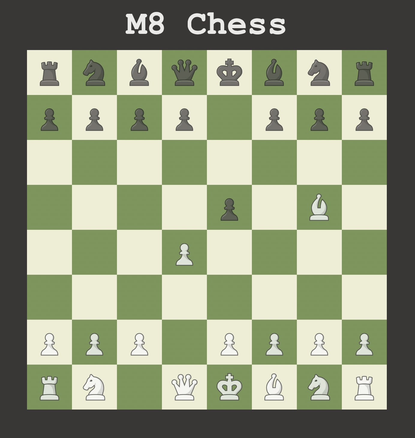
For this week I developed a fully playable chess app using only
JavaScript, HTML, and CSS!
Notice that the app does not work on certain browsers (like Safari) but does work on Chrome.
The app sends data to my Firebase database from week 10 and will be used as an interface for my final
project.
I followed this tutorial to create the basic game
logic but had to fix some bugs it had.
I also changed the UI to match popular chess apps and added all the database communication.
Finally, I used firebase hosting to allow convenient access to the app from any device connected to the
internet.
-------
Week #12
mechanical machine design
Machine week was a lot of fun! Together with my lab mates, we built a cool drawing bot that process images
and draw a filtered version of them.
I was curious to learn more about the mechanical aspects of building a machine and specifically designing a
gantry system.
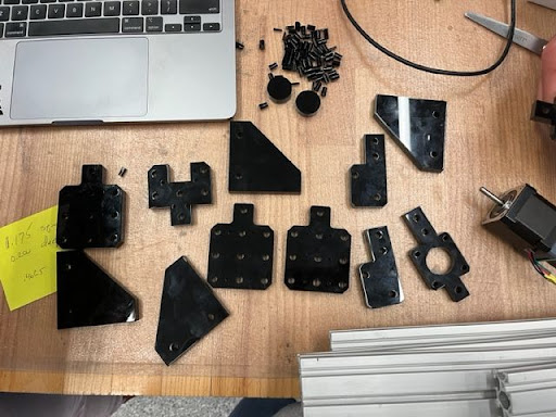
We divided the work into different tasks and assigned a few people to each of them.
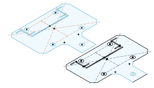
I was helping with designing and cutting the parts and with assembling the gantry system.
It was a great way to see firsthand the challenges of designing a mechanical machine and the constraints
that should be taken into consideration.
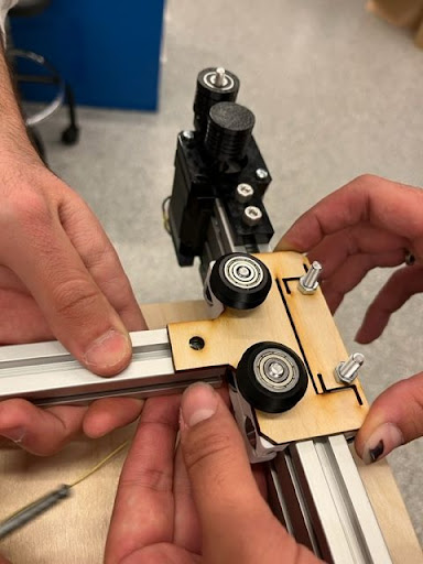
A major challenge we had while building the gantry was to make the wheels' mounts fit well to the aluminum
extrusion. We solved it by adding fractures to the parts, to create more pressure between the wheels and the
rail.
The integration between all the different groups was great, and I was proud of the overall result.
-------
Week #13
wildcard week
Although I was eager to learn how to weld, I wanted to use wildcard week for my final project. I wanted to
use the CNC lathe we have at the EECS shop to make the chess pieces for my final project.
This is a great opportunity to thank Anthony for removing the dust from the old machine and setting it up
for this job. Although he likes to complain about this machine, I had a great time using it and felt very
comfortable working with it at the end.
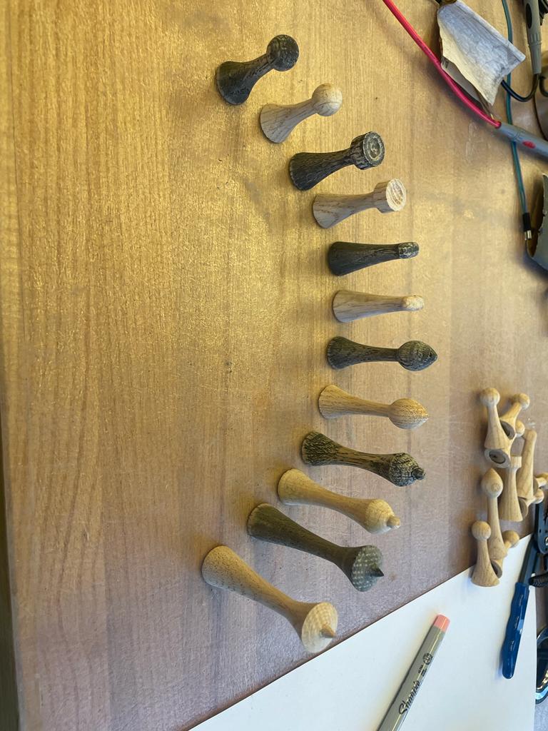
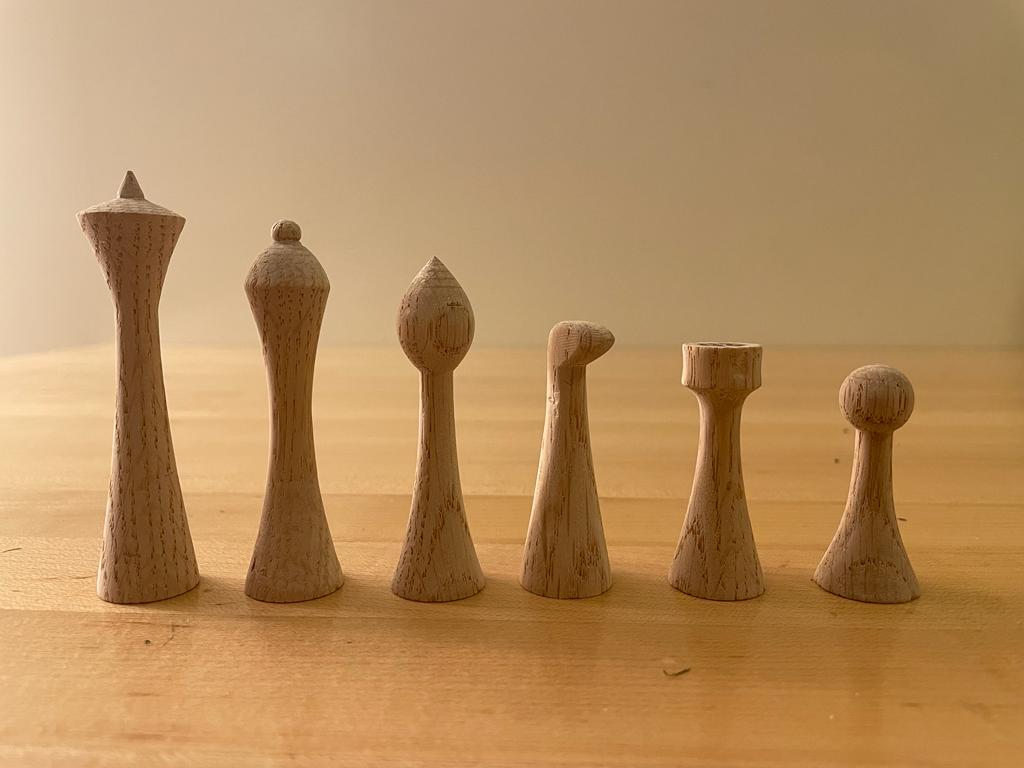
I designed a chess set with a modern look to match the 'innovative' feel of the project.
The most challenging piece was the knight since it is not symmetric like the other pieces.
I designed the knight with a revolution of its head and then cut and filed it manually. I also used a Dremel
to decorate the rook.
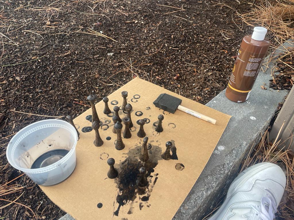
I used black wood stain to color the black pieces of the set and sanded all the pieces for a smooth finish.
This was one of the most fun weeks of the class for me!