Idea
I want my camera housing to be lightweight, sturdy, and economic. The former two likely need no further explanation, and by economic I mean that I do not want to
waste endless amounts of 3D printing filament just because I could. The ideal housing I envision has some sturdy structural elements that keep it together (maybe 3D printed), but
uses some sheet metal or other flat material for its outside case (maybe aluminum). I am particularly inspired by the architecture of CubeSats, which probably rank quite high
in the three categories I am trying to achieve. I will model everything in Fusion 360, where I've also built my custom PCB boards, and then machine the structural elements on a 3D printer and
the outside cover panels on a waterjet. Let's begin!
Modeling the Camera Body Frames
As the dimensions of my camera housing primarily evolve around the electronics inside of them, I started by taking the dimensions of my image sensor PCB and the motherboard, as well as their connected
peripherals, which I have designed over the past weeks. Fusion 360 natively offers the ability to create 3D PCBs from your 2D PCBs and then import them into your 3D objects, such that you can directly see the physical PCB you created inside its enclosure. While I would have loved to try this feature, I
deemed it overkill for a simple board like mine and did not pursue it further. If you want to try it, this guide by Autodesk is a great starting point. The unofficial way is to simply measure the dimensions of your
PCB in the 2D PCB tab of your electronics design and then create a sketch with the correct dimensions in your 3D enclosure file. This is exactly what I started with in a new Fusion 360 project.
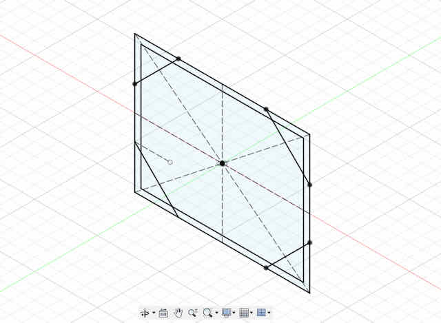
The base sketch defining the dimensions of our camera, driven by the dimensions of the image sensor and the motherboard
My camera body should be composed of two support frames: one for the back of the camera, giving the user access to the menu buttons and a screen, and one for the front of the camera, which gives access to the lens. The two frames will later
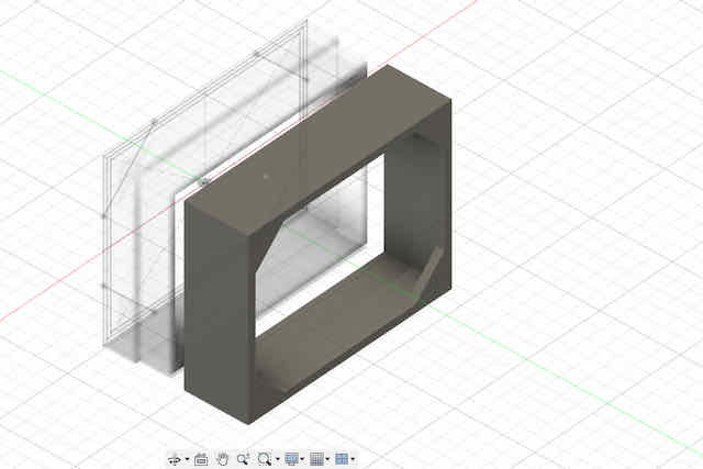
be positioned a few centimeters apart from each other, and the whole structure will be covered up by sheet metal. First, I modeled the back frame. I used the PCB dimensions sketch created earlier and offset it to leave a small margin
around the board outline. I then created 4 walls around that base, forming a tunnel-like structure. To support the structure, I added chamfers in the corners. Note that I later want to mount sheet metal with cut-outs for the user input to this
frame. Next, I created a second frame with a similar but inverted setup that I could use to mount the motherboard with the image sensor to. The reason I created a second frame is because I wanted to be able to mount the user input peripherals to the back
of the sheet metal enclosure, and then attach the motherboard later. The second frame simply slides together with the first frame to create one support frame for the entire back of the camera. I later realized that the second frame (that slides over the first)
is likely redundant in my design – you can actually merge the two together into one frame. Nevertheless, I chose to keep this design to be able to open my camera more easily for demonstration purposes.

The first frame at the back of the camera will allow us to mount a metal casing onto it
The second frame holder to mount the motherboard onto
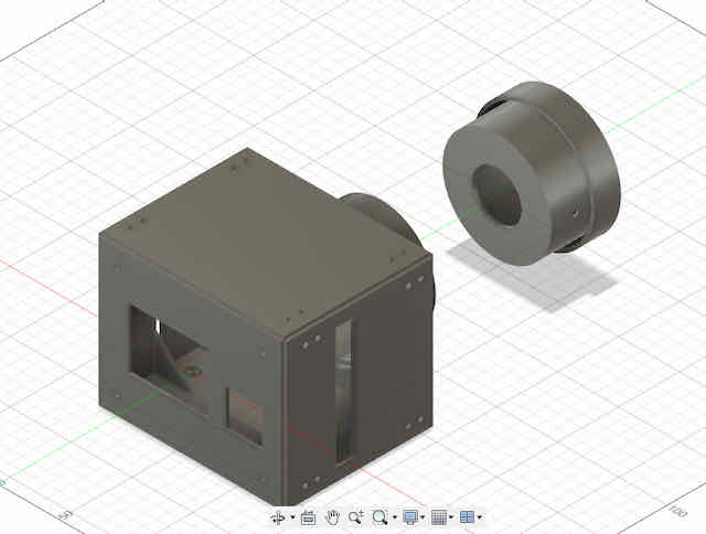
The second support frame will support the camera lens and close off the front part of the camera. For this frame, I projected the relevant dimensions of my
first support frame, but this time closed the base. I then created a new sketch that defined the camera lens diameter. Projecting the lens diameter onto my front support structure
sketch, I cut out a circle with a diameter large enough such that a custom lens adapter I modeled later could just fit through the hole. I also modeled a lens adapter from the same sketch that could
be inserted from inside the camera body through the hole to provide a support structure to the camera lens setup.
Last, I considered where my frames needed to have indentations or cut-outs for other peripherals connected to my camera. I only needed to make room for a potential exposure button board I wanted to make in the future,
so I created a cut-out at the top of the first support frame. Last, I arranged all parts exactly as they would appear in the assembled camera to start measuring and modeling my
sheet metal panels.
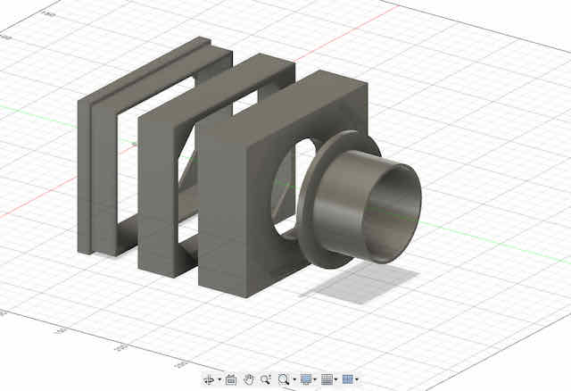
The entire imaging train of the camera, with an added lens adapter

I also added cutouts for the cameras buttons and interfaces
Modeling the Camera Body Enclosure
The frames we modeled so far provide the structural support for the internals of our camera body. As I previously said, I want to use a flat material like sheet metal to finish the
enclosure. In this part, we are going to model these enclosing sheets. Note that we need to model six sides for our camera body to be fully enclosed: top, bottom, left, right, front and back.
I started by creating a new component for the enclosing sides and created a new sketch. By projecting the dimensions of the internal frames to this sketch, I quickly had the rectangles I needed
as the bases of my sides. I simply extruded them a millimeter thick (the thickness does not matter in my design, as it does not influence any other components).
The projections of the imaging train frame holders serve as the basis to model the sheet metal parts I want to make my casing out of
Last, we want to add some simple mounting holes to both the frame holders and the sheet metal sides, to attach them to each other. I decided on screws with a 4mm diameter, and gave the mounting holes a
diameter of 5mm. Obviously, there is a lot of play around the screws later (±0.5mm), but I think this is acceptable for a simple box like this. The screws will later be put in from the outside sides to the inside,
where I will secure them with nuts. I did not use Fusion's hole feature which lets you create threaded holes, since I did not want to deal with 3D-printed threads. Instead, I simply added circles with the right diameter
to sketch planes on my sheet sides, which I then cut-extruded to cylinder holes. Last, I also created some cutouts to access the peripherals of my camera, like the SD card, micro USB, and programming pins. While designing these cutouts,
I noticed that I had trouble accurately planning their dimensions since I did not use a 3D model for my PCB, so I measured them out as best as possible and decided to later first cut a prototype from cardboard, before
cutting the final enclosure from sheet metal. This finishes the simple design of my camera body. I may choose to drill some more holes manually later, but this is enough for a version 1.

Adding mounting holes to fix the sheet metal plates onto the frame
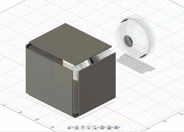
The final body frame and enclosure
3D Printing the Camera Body Frames
We are going to create the study camera body frames using 3D-printed PLA. In my case, I will be using a Prusa 3D printer, but you can choose to go with any printer.
First, I exported the individual frames (each as their own component) as STL objects, by right-clicking the respective component and exporting the component accordingly.
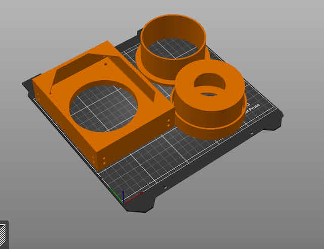
To slice my object for 3D printing, I used Prusa Slicer, imported my STLs, and played around with their orientation until I could fit all parts on two printers with a print time
of around 6 hrs each. I used the default settings for a 0.3mm DRAFT print quality with an infill of 10%, but this did not matter much since most of my elements are made up of
walls or flat elements, which are usually filled 100%. I later discovered I could only use one Prusa printer, so I printed some parts on that and some other parts on a different printer with a different software.
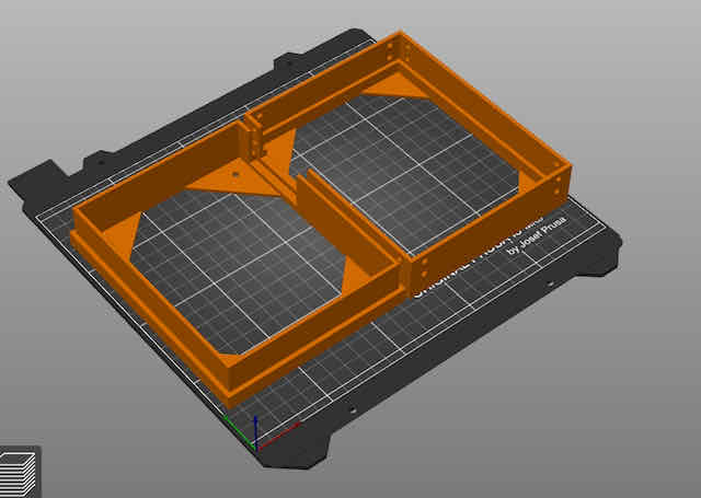
Slicing the imaging train frame
Slicing the imaging train frame
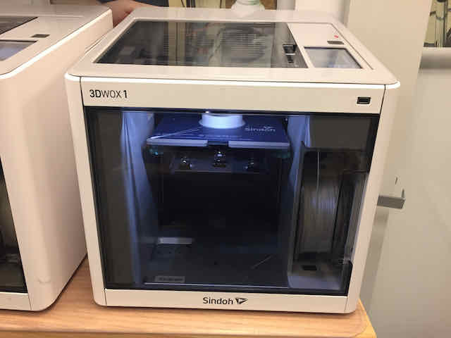
Printing the components using FDM 3D printing in the EECS makerspace
Laser-Cutting the Enclosure Prototype From Cardboard
Although I want to make a final version of my camera body from sheet metal, I deemed it a good idea to laser-cut the enclosure from cheap
cardboard first, to test the dimensions of the cut-outs and the overall design. I exported the six enclosure sides from Fusion 360 using the SVG export function of the
Shaper Utilities add-in.
I then fixed them up in Illustrator and prepared my file for laser-cutting on a Universal Laser Systems laser cutter. This meant that I had to remove any fill from my objects,
set the contour to #FF0000 in RGB color mode, and export everything as a PDF. I cut my parts from some spare 3mm corrogated cardboard and then assembled the whole camera body.
Hacking the Lens from an Old Pair of Binoculars
Ok, our camera body is almost fully done. Obviously, one big element still missing are our optics. To be fair, I saved a lot on this element and did not invest much
time into it. This is simply because a camera with 16x16 pixels does not really gain any advantage from good optics – your image will look pixelated, no matter what. Therefore,
choose something like an old pair of binoculars, a monocle, or a magnifying glass off eBay. Through trying a bunch of these options, I discovered that pretty much anything should work – in terms
of focal distance, these will all be around 10cm or so. By measuring out my lens with calipers, I previously created a funnel-like 3D enclosure that could be mounted inside a
tube and holds the lens in place. All we still need is a tube to bridge the distance between our lens and our image sensor, which is what I used a thick cardboard tube with 10cm diameter for.
You may also use a PVC tube used for plumbing or anything similar from the hardware store. Even better, choose two tubes that fit into each other, so you can adjust the focal distance.
To find out our focal distance, we can put our lens in front of a source of light and try to see where it creates a projection. The distance between the lens and the
projection screen is our focal distance. Note that the focal distance changes, based on how far away an object is from the camera lens (obviously, when an object moves out of focus,
we have to adjust the focus to accomodate for the new distance to the object). In my setup, I simply put my binocular's lens into the cardboard tube I had bought and prepared, using the 3D-printed mount.
I then put the lens in front of a source of light, dimmed the rest of my room, and held a piece of paper at the other end (where the image sensor will be) to see the projection of the light source.
In the picture below, I actually held the lens the wrong way, so don't be confused by it. The lens should be oriented like it will when attached to your camera.

The light source and lens I used...
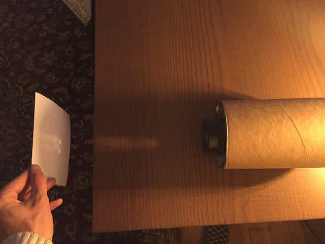
...which create a projection right at the focal distance to the projection paper
Once we have adjusted our focal length by cutting the lens tube to the right length, or having it flexibly move in another tube, we can mount the whole
lens to our camera body and should be able to observe the same projections in focus, displayed where the image sensor goes. I quickly mounted the setup together
and then put a piece of paper where my image sensor will go. Leaving the underside of my camera open, I could clearly see an inverted projection of the lamp I
pointed my lens at in this example. It isn't perfectly in focus in the shots below since I was trying to hold the camera with one hand while taking a picture, but
it demonstrates that the mechanism works.
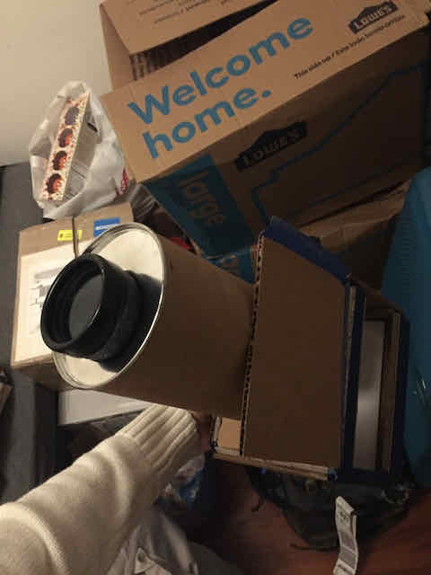
The assembled camera with a projection on a piece of paper inside

More details on the projection, this time the light source is in focus
From this point, it should be very obvious we are extremely close to taking our first image! We simply have to move our
image sensor and electronics into the camera body, mount our image sensor where our paper currently is, and start taking images!
Assemblying the Cardboard Camera Prototype
The prototype looked solid and was quite a bit more study than I had expected, so I decided to stuff my camera and move all the components into the camera body for a first test.
For now, I connected the image sensor and the motherboard using jumper wires, though this is just to save time in debugging the image sensor. I will later use the 2x5 male and female headers on
both boards to connect them in our final version. While the cardboard look and feel may not appeal to everyone, I think it is a perfect prototype before we produce the enclosure parts from sheet metal.
I put all the components into the camera body and closed it using some blue tape.

This is the demo setup I used for my prototype. Notice the jumper wire connections between image sensor and motherboard

The final V1.0 camera model with the image sensor and electronics mounted inside
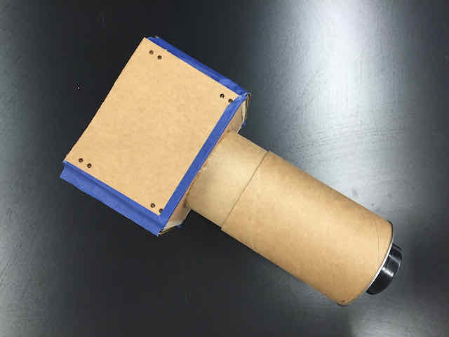
From above, with adjustable focus

Showing the perspective from the back panel
Summary
This finishes the physical design of the first prototype of our 16x16 DSLR camera. While we did not get to producing a final enclosure out of
sheet metal yet, I hope the process shows you how to do so nonetheless. I will work on updating the final design in a future milestone, though I am really
excited to see some first images and this cardboard version will do the same job. We learned how to build an enclosure around our internals that has 3D-printed
components that hold everything together. We then built a flat-material enclosure around it. Last, we hacked a basic camera lens to give our camera the ability to
project an image onto our photosensitive area – in my case, this will be the image sensor. In our next and last milestone, we will finally
upload some code to the camera and take a look at some first images taken with our image sensor.