Idea
So far, we have produced a custom image sensor with a 16x16 pixel resolution and a mother board. We have also built a custom camera body
to house our camera components. Now is the time to finally upload some code and see our camera in action. This post will be relatively short,
as I only want to achieve one milestone in this post: getting a first image from our camera. We will learn a bit about Arduino programming and
use Processing to display images. In the future, I will upload a post about code that also makes use of camera peripherals like an LCD screen.
This is the eigth and last milestone in a series of posts that cover my final project, where I will be creating a 16x16 pixel DSLR camera from scratch. In my case,
from scratch literally means milling the PCB for the electronics and stuffing it by hand, figuring out the optics and then putting everything into a nice
housing of 3d printed parts and flat panels. By the end, we will hopefully have a working model of a DSLR camera that can (natively!) produce cool pixel-art images
and demonstrates the inner workings of a modern-day DSLR camera.
Writing the Code to Capture an Image
The general logic of taking an image with our custom image sensor is relatively simple: We have a 16x16 array of pixels, where
each pixel has a unique combination of row, column. Our first pixel is a phototransistor at row 0, column 0 (0, 0). In order to read
out the "light level" at that unique pixel, we use a multiplexing approach. Specifically, we let our row-selecting multiplexer turn row 0
to HIGH, while all other signals are run at high impedence. This activates all phototransistors in row 0. Now, to only read the first pixel, we
use our column-selecting multiplexer to read just the input value in column 0. Review our circuit logic here from earlier again if you need
a refresher on how our image sensor is designed. This gives us the relative light level at pixel 0, 0.

A reminder of the circuit of a single phototransistor. Activating the collector allows us to read a voltage on the emitter w.r.t. ground
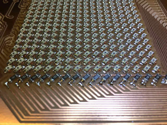
Notice the rows and columns on our image sensor, which we control in code
To read an entire image, we simply loop over all rows and all columns and read out the current light level sequentially. When all image sensors have been
scanned, we have successfully taken one exposure. Note that this is a bit different from the mechanism modern-day image sensors use and dramatically
slower, but it provides an easy prototypable version. In my code, I do exactly that. I simply uploaded my code to the motherboard using
a D11C programmer, which I've built in week 3.

Writing the code to read out our image sensor
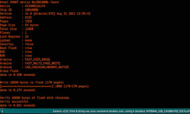
I then uploaded the code using my D11C programmer
Displaying an Image
Before we print out an entire image, I thought it would be a good idea to print out some pixels using the serial print function
in Arduino IDE. So I added debug lines that printed the value of the first pixel every second to the log. In our serial plotter, we can
then see these values printed on the y-axis over time, displayed on the x-axis. I found that I could successfully turn the sensor dark by
placing my finger above the sensor, and read a light level while I removed my finger and ambient light was hitting it. This was a promising start.

A quick check with a single pixel to make sure it reacts to varying light levels
I then turned to Processing, an Arduino-compatible app, to display the analog values I was reading from 0 to 1023 as greyscale square rectangles (from black to white).
This is basically how each pixel works: we read out its measured light intensity and the value represents light from black to white. I based my
Processing script largely on Sean Hodgin's fantastic camera project and adapted it to my 16x16 image sensor.
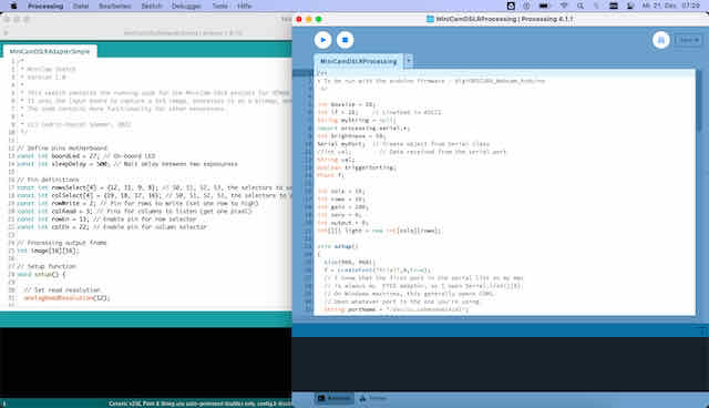
Running Arduino IDE's serial connection and Processing, with my camera connected via USB

A first test image showed I still had some software bugs
I was quite surprised by the live feed I was getting from Processing, as I had not imagined my image to be this dark. Luckily, I found
that it was a simple software bug: I had driven the EN (enable) pin of my multiplexers HIGH, when in fact, the datasheet showed I had to
drive it LOW to enable it. I also had to drive the CS (chip select) pin LOW, and not HIGH. These two fixed my problems and my image sensor
produced some legible black and white images for the first time.
Taking Test Images
The following is a gallery of test exposures and images I have taken with my image sensor. You will notice that most of the ones I
selected appear white and with black shaddows. Unfortunately, it seems like I have chosen relatively small resistors for my columns, which means my
image sensor is not very light sensitive and usually produces mostly dark images. Therefore, I positioned a bright light source right in front of it
and tried to image shaddow projections of features in my lamp or other things I could find flying around the lab to get something onto the image sensor.
While these shots are not very impressive to the keen eye, they were immensely helpful for me to test and debug individual pixels.

Test image of looking at a light source to make sure all pixels are exposed and working

Test image of holding a pen in between the light source and camera lens

Test image of features on the lamp

Another test image of a cardboard silhouette in front of the lamp
Summary
This ends today's milestone. We successfully programmed our image sensor and motherboard to take images with our custom-built DSLR camera. We then used
Processing to display these images on a connected computer in a webcam-like application. We successfully took some test photos. I will end this milestone here, since these are the final images I presented on demo day for How To Make Almost Anythign 2022.
At this point, due to the resistor values I chose, our camera is not fully usable to take images indoors yet. It needs to be pointed directly at a light source and can only really image shaddows (high contrast).
In our next milestone, we will refine the camera exposure resistors so that we can also take images of real subjects. Still, I think seeing these first images, especially the shaddow figure, is a promising first step and shows what
kind of images this camera will be able to take later.