Idea
This week, I am going to design my first custom PCB board from scratch. The functionality
of this board will be rather simple – but it's also the first board I am ever designing.
The board will be based on the ARM SMD D11C chip and has an LED connected to one and a tactile
switch (button) connected to another pin – giving us a simple Hello World (Echo Board) that should
light up the LED when pressing the button. I used Eagle (fully integrated into Fusion 360) to design the
board, a 1/64 in endmill to mill the traces, a 1/32 in endmill to cut the board, and the Arduino IDE
to write the code for the board. The design is based on Neil Gershenfeld's echo board and code,
which can be found here (scroll down to "ATSAMD11C").
Designing the Echo Board
This was the first time I designed an electric circuit. I decided to use Eagle, which was
bought by Autodesk and is fully integrated into Fusion 360, since I am a Fusion user already. Moreover,
the Fusion integration makes it easy to switch between a view of the CAD model that houses the
board, and the board itself with correct dimensions. I started by following along
Jake's great tutorial "Eagle in 10 Commands" to get familiar with the most common commands. Although it took
me about twice as long to get through the tutorial, it greatly sped up my progress afterwards. A great starter!
Before starting my design, I imported the design rules (.dru) from the class and the library (.lbr) for the footprints
of the components I wanted to use, which can be found in this repository.
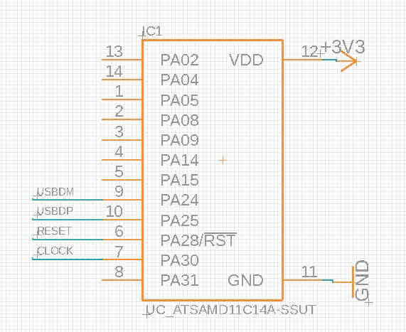
First, I added all components I wanted to use in my board, and roughly organized them in the way I wanted to assemble them on my board later. I also
added value labels to my resistors and capacitors to later remember which one to use during soldering. Next, I used nets to wire up all
components accordingly. The name command was especially helpful here, since it allows you to connect two pins without drawing a wire all the way
throughout the design. Basically, I compartementalized all parts of my board into the individual "pockets of components" on the board.

Adding all components to my board schematic
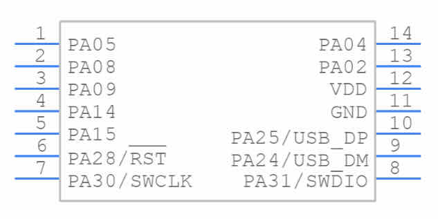
Using Google to find the pinout of the microprocessor...
...and then finding the right pin in my Eagle schematic
Last, I used Eagle's design rule check (DRC) to see if I had any errors with my board. Now I think is
when I realized that Eagle is much more powerful for designing circuits than just a graphics program. I quickly
fixed up the errors I had and then moved putting the PCB board together.
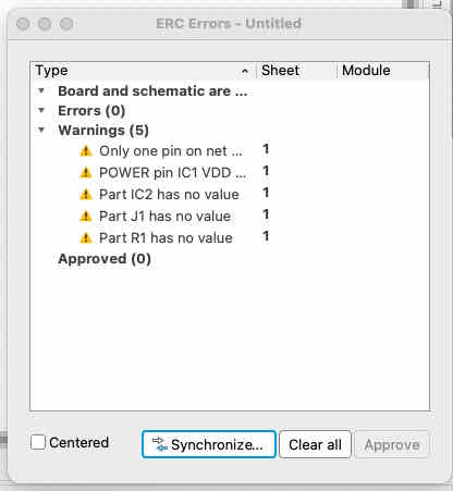
Finding errors in my schematic using Eagle's DRC feature
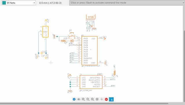
The final schematic of the board
Designing the PCB board
After finishing the schematics, I switched to Fusion's PCB tab. I began by placing the components onto the
plane and playing around with the arrangement of them until I found positions and orientations that gave me the least
overlap (and headache) with respect to the wiring.
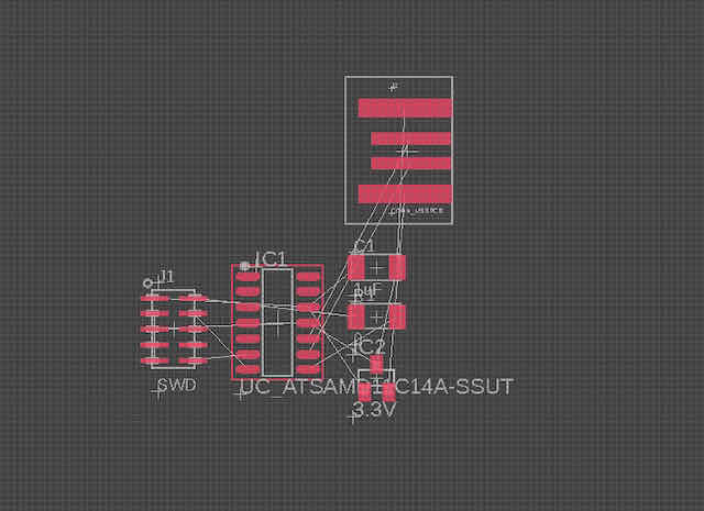
The components without any arrangement
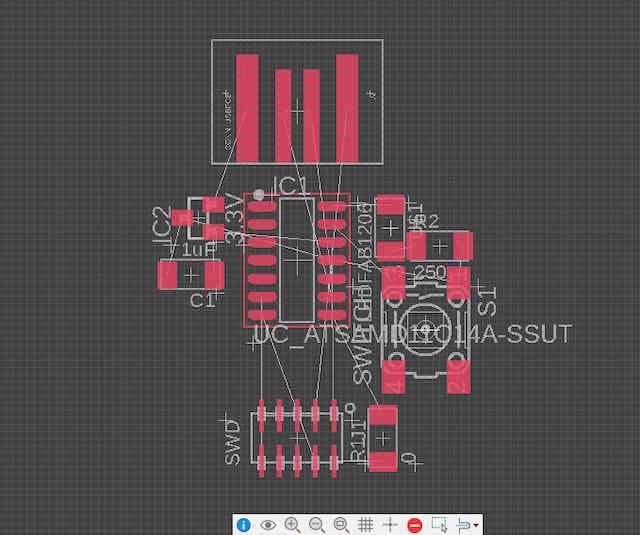
The rough arrangement that leaves the least overlap I could achieve
I continued by wiring the components according to their airwires. Unfortunately, some of the wires I wanted to fit under components did not
go under the components I wanted to run them through (the mill clearance did not allow for these traces to fit under my components). As I could not find
any way to fully eliminate this problem, I had to add a second 0-Ohm resistor as a bridge over a trace. Furthermore, I routed
some wires very close to each other under the processor without any necessity to do so. I moved these wires further apart, not because it was required by the
design rules, but because I felt it would just make it easier to manufacture. Last, I drew the board outline around the board.

I wanted to run this connection under the 2x5 connector, but it did not fit
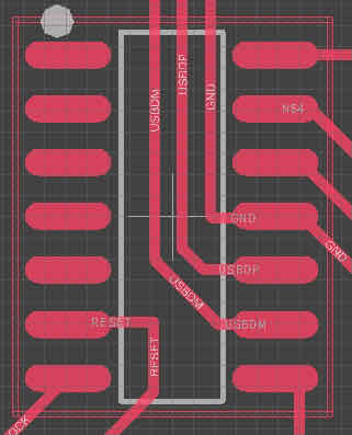
The USB data lines fit nicely under the microprocessor

The arrangement of the LED, a resistor, and a tactile switch (button)
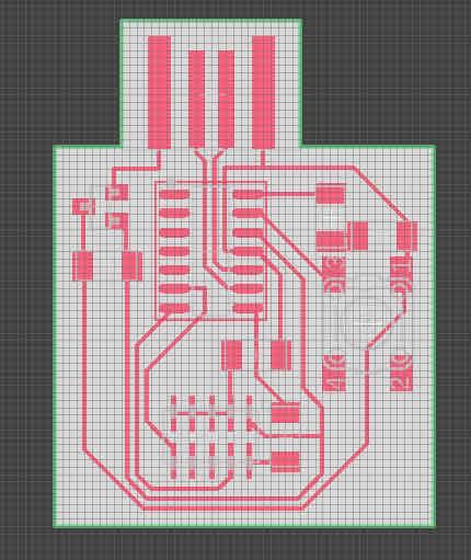
The finished PCB board
Before moving on to exporting my board design, I ran a design rule check on the PCB board to make sure
everything was right. Again, I love this feature, since it allowed me to quickly fix up some minor issues and know
that my design is printable by the endmill. Luckily, just before exporting, I realized that I should have added a pull-up
resistor to the button to prevent its input pin from reading a floating input (if you want to know more about this problem,
this YouTube video by AddOhms helped me understand it greatly). So I went
back into the schematics, added a resistor from the button input pin to the 3.3V line, and tried to fit it onto my PCB board in the PCB
tab. To save space and avoid rewiring the PCB, I fit the resistor under the for now button and hope it will fit under it.
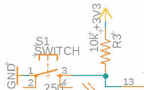
The pull-up resistor I added later to my schematics
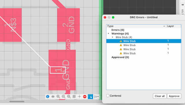
Checking and fixing my final board with a final design rule check (DRC)

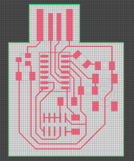
The finished traces to be milled with the 1/64 in mill
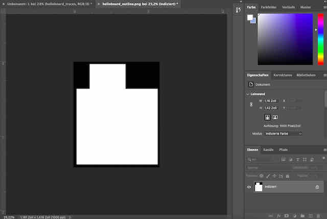
The finished board outline to be cut with the 1/32 in mill
Milling the board and soldering the components
I was confident in my design and made sure both exported PNGs with the traces had just the areas to mill in white (there
were some issues around the border of my exported image, which I fixed manually in Photoshop). I exported both designs to the
endmill machine as PNGs. After mounting a fresh copper board and fixing it with double-sided tape at the bottom, I started milling
the traces. Unfortunately, I discovered that although I adhered to the design rules and did not override the spacing, the wires
came out very thin and fragile. Moreover, one section of the 3.3V and the ground wires on the bottom were not cleanly separated.
At this point, I realized I could have given all wires a wider with from the start, as space was not too limited for the board I designed.
I selected all wires as a group and used the change tool (wrench icon) to change the wire width of all wires from 0.15 to 0.39. I also
manually redrew some wires to give them more space.
![]()
The milled traces came out quite thin, and there was a short in the bottom
The wires with thin wiring

The wires with extended wire width and extra spacing where possible
Both interventions fixed the problem with milling. When re-milling the traces, they came out cleanly separated and much
stronger than before. Cutting the board with the 1/32 in mill also went clean. After scratching off any excess copper with a metal ruler
and washing the board with dish soap under water, I proceeded to soldering. For soldering, I again stuck the board under the microscope with double-sided tape and worked entirely under the microscope. Again,
I used a very thin lead wire at a temperature around 750F and needed no extra flux. The learnings I had written down two weeks ago
when soldering my first board under the microscope (here) were extremely helpful here and I could
solder all components on within about an hour.
![]()
The fixed board with wider trace width and clearances
![]()
Soldering the components under the microscope
![]()
The finished and soldered board
Programming the Echo Board
To finish this week's project, I tested and programmed the Echo board with a script that sets
the pin of the button to an input pin and uses the LED as an output pin. I used the programmer
I built in week 3 , in its programmed state, to write the bootloader and then Neil Gershenfeld's Echo Board script
to my Echo board, by connecting the 5x2 output (TARGET) side of my programmer to the 5x2 input (SWD) side on my Echo board. I used
OpenOCD to write both to my board which went without issues.
After writing the script to my board I tested it's functionality – it worked just as planned and the LED
lights when the button is pressed. Way to go to design more complicated circuits, but this is a great success for me for this week.
![]()
The programmer and the Echo board are both connected through a 5x2 connection
![]()
Writing the script to my Echo board
![]()
The finished and functioning Echo board in action