Embedded Programming
✔️ Compare the performance and development workflows for other architectures
Individual Assignment
✔️ Browse through the data sheet for your microcontroller
✔️ Use your programmer to program your board to do something
✔️ Extra credit: try other programming languages and development environments
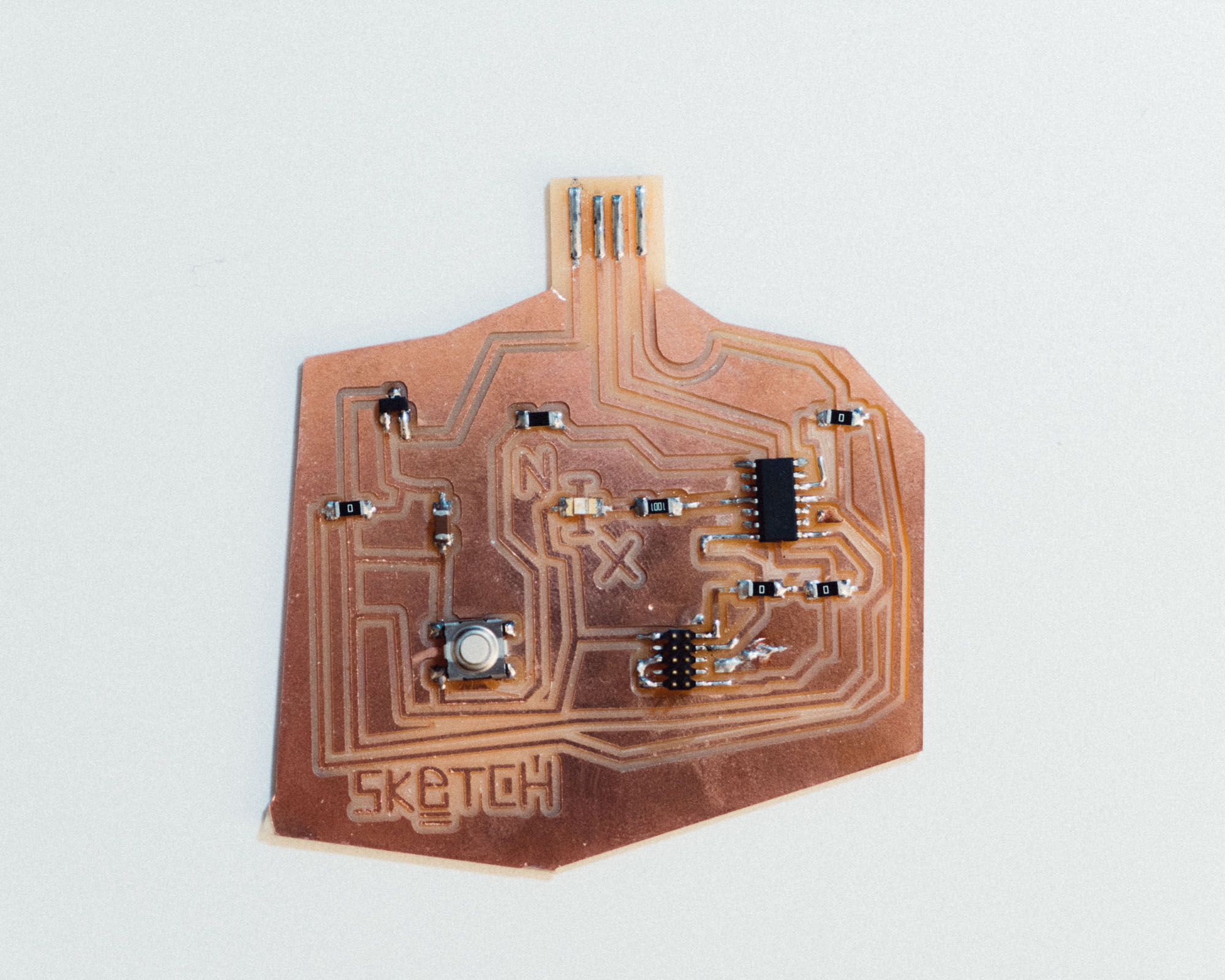
SKeTCH Board
I choose ATSAMD11C for this week's assignment.
Toolchain
Arduino IDE (with Arduino code) -> compiler -> machine code
Check SAM D11C Datasheet
I started to skimming through the 981-page Atmel SAM D11 Datasheet to get an overall sense of how a microcontroller works. I particularly pay attention to the pinout part.
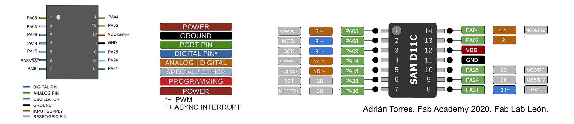
- VDD: Supply voltage.
- GND: Ground.
- Digital pins: PA02, PA04, PA05, PA08, PA09, PA14, PA15, PA31.
- Analog pins: PA02, PA04, PA05, PA14, PA15.
- USB pins: PA24, PA25.
Analog Pin
Can take a range of values. This pin reads/writes voltage anywhere within a range from 0 to 5V. An analog pin can usually be used as a digital pin.
Digital Pin
Can only take one of two values (LOW or HIGH). Digital pins are mainly used as output pins. You can use them to check an on/off status of a switch (input) or you can use them to turn on/off devices (such as a buzzer, LED, LCD) using HIGH and LOW in the Arduino code, for example. Note that PWM (pulse width modulation) is a way to get analog results with digital means (using a square wave , for example blinking an LED at different frequencies that appears to the eye as different levels of light)
The D11C is part of the SAM D family of boards, Atmel brand. It does not need much power (low-power) and uses a 32-bit ARM processor. Higher bits means higher handling of data and higher ability of handling more RAM (memory).This version that I am using has 14 pins (10 of which can be used for input/output), including digital & analog pins. This microprocessor has 16KB flash and 4KB SRAM. Flash is a type of memory, which is cheaper and slower than RAM. SRAM is static RAM (as opposed to dynamic RAM, DRAM). This SAM D11C operates at a max frequency of 48MHz and reaches 2.46 Coremark/MHz. The frequency typically refers to the frequency of the main CPU clock / frequency at which the clock generator of a processor can generate pulses.
All I/O pins can be configured with internal pull up or pull down resistance.
Note: In Arduino IDE, the pin number refers to the number after PA, e.g. 04 for PA04, rather than the number 1 on the SAM D11C.
The Process
Note: The following steps are for Windows 10, even though the process is similar for other OSes.
1. Install bootloader to the new board via the USB Programmer made during Electronic Production week with OpenOCD.
1. Install OpenOCD (Open On-Chip Debugger)
What is OpenOCD?
- a software to program microcontrollers
- a realtime debugging tool
On Windows, there is no package manager. But you can grab binaries here. Once you've downloaded the latest release, unpack it and put it wherever you want it to live. The important file is bin/openocd. You can either type out the full path whenever you want to run it (e.g. something like C:\\Program Files\openocd\bin\openocd, instead of just openocd), or you can add the bin dir to your path. (See here or Google elsewhere for instructions on adding directories to your path.)
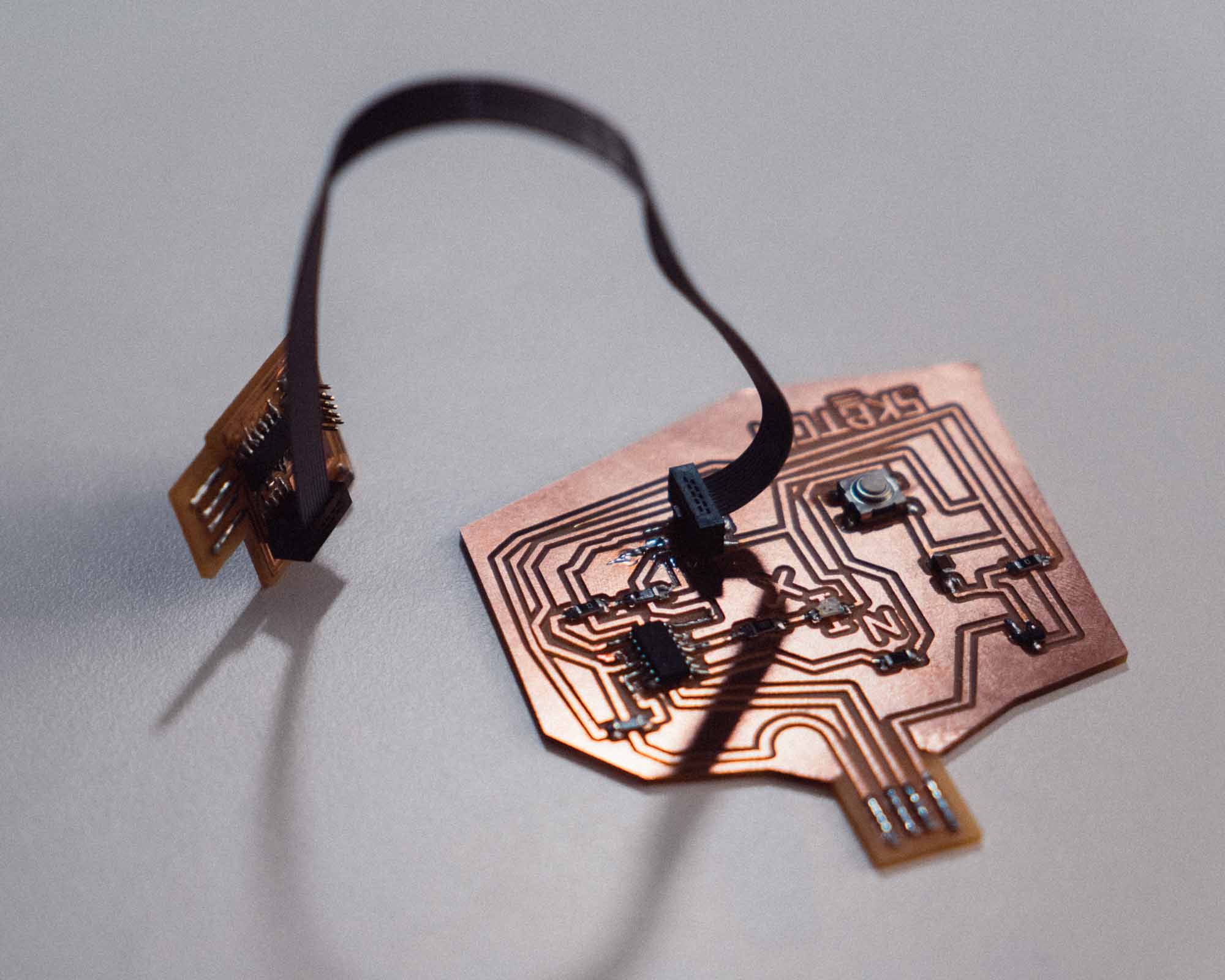
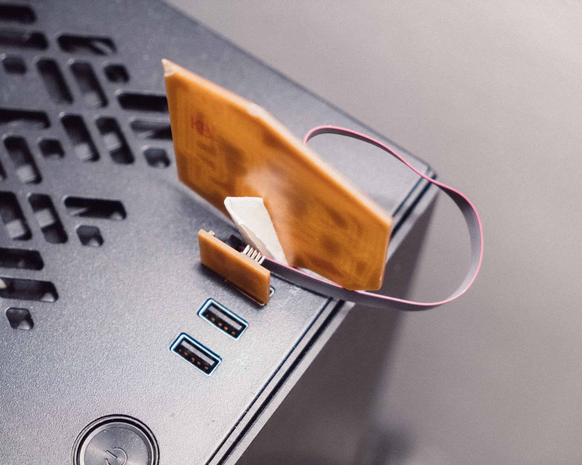
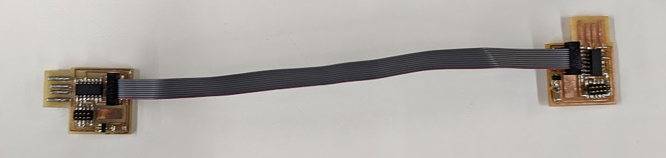
2. Connect Programmer and the new board.
Make sure the 2x5 Pin Ribbon Cable is connected to both boards in relatively the same orientation.
Make sure both are powered and power the board being programmed first. That means plug the new board into the USB first.
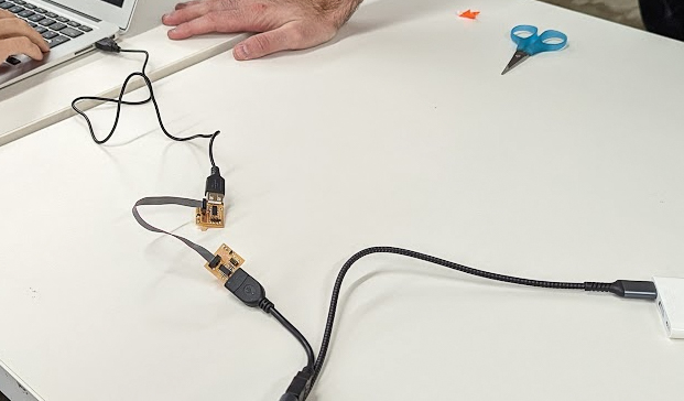
Image Source: PROGRAM_PROGRAMMER.md
3. Download d11c14 bootloader to a folder.
4. Open any command-line interface, navigate to the folder mentioned above, run openocd.
It should find the openocd.cfg file, read that, and use it to program the .bin file onto the microcontroller.
Then I see a message which includes:
%20Anything/SCREENSHOTS/Screenshot%2020221028050728.png)
It means the bootloader has been successfully installed to the new board.
2. Programming with Arduino IDE.
1. Setup Arduino IDE.
Download the Arduino IDE from here.
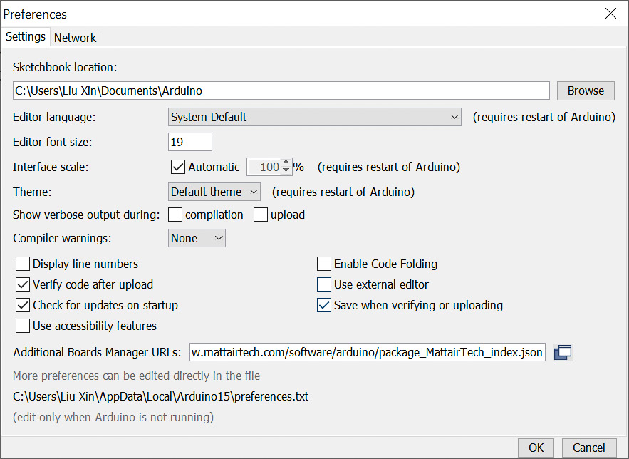
Navigate to File > Preferences.
Then in Additional Boards Manager URLs paste this link:
https://raw.githubusercontent.com/qbolsee/ArduinoCore-fab-sam/master/json/package_Fab_SAM_index.json
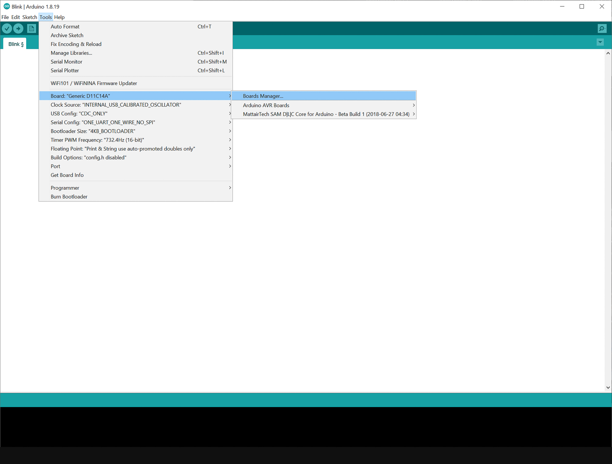
Navigate to Boards Manager.
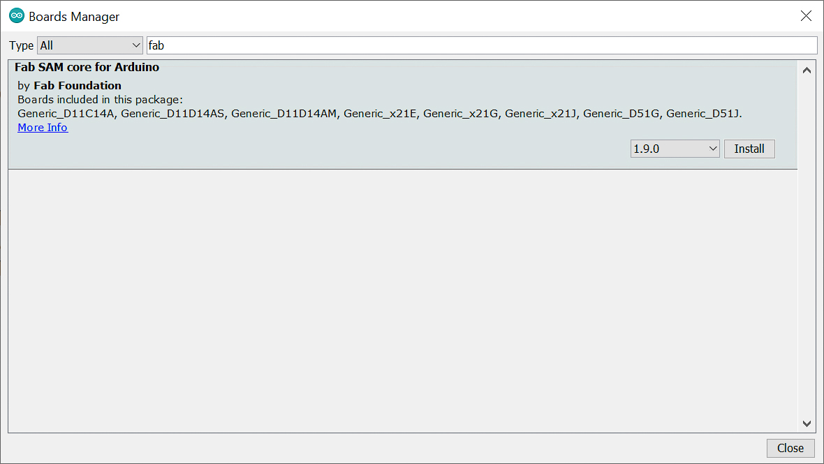
Search for fab.
Install Fab SAM core for Arduino by Fab Foundation.
2. Programming.
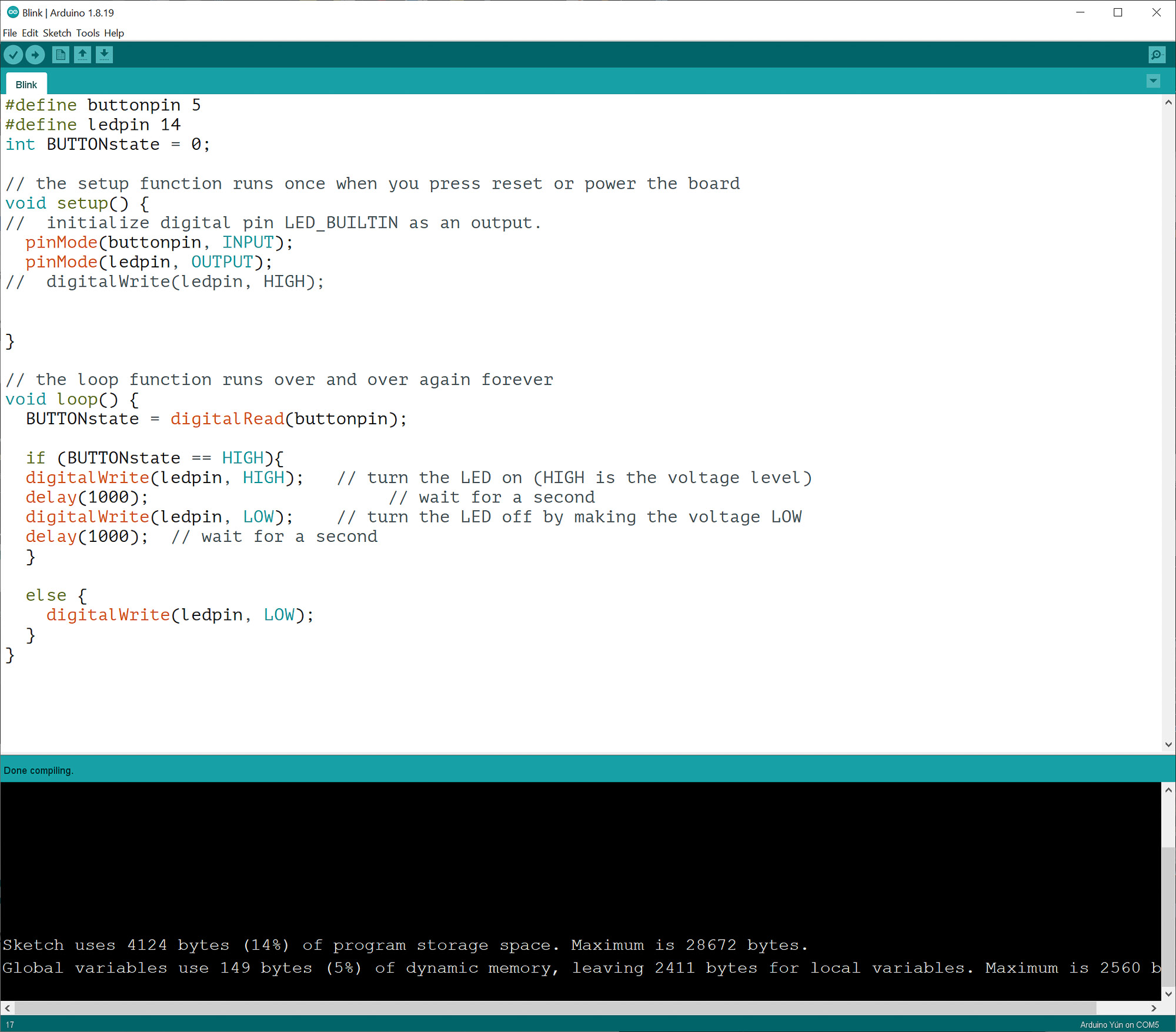
You'll have to know how your board is designed to identify which pins should do what. Here is my code:
#define buttonpin 5
#define ledpin 14
int BUTTONstate = 0;

// the setup function runs once when you press reset or power the board
void setup() {
//  initialize digital pin LED_BUILTIN as an output.
  pinMode(buttonpin, INPUT);
  pinMode(ledpin, OUTPUT);
//  digitalWrite(ledpin, HIGH);


}

// the loop function runs over and over again forever
void loop() {
  BUTTONstate = digitalRead(buttonpin);

  if (BUTTONstate == HIGH){
  digitalWrite(ledpin, HIGH);   // turn the LED on (HIGH is the voltage level)
  delay(1000);                       // wait for a second
  digitalWrite(ledpin, LOW);    // turn the LED off by making the voltage LOW
  delay(1000);  // wait for a second
  }

  else {
    digitalWrite(ledpin, LOW);
  }
}
3. Uploading to the Board.
To load this onto the board plug the board in. Select the appropriate port and board.
Click on Verify to verify the code before uploading.
Then click Upload to load the code onto the board.
Resources
Programming the Programmer / Installing Bootloader