Week 10
Output Devices
Flexible Crown PCB, Charlieplexing and artificial muscles
The Crown
The inspiration for this week's project came from a few weeks ago. I was in awe of Quentin Bolsée and Jack Forman's flexible PCB (linked here), particularly because I found it so fun that something as rigid as a PCB could be flexible.Crown Design
I had a specific idea in mind: a crown-shaped flexible PCB with LEDs everywhere, because you can never have enough sparkle in your life. I designed the crown shape in InkScape: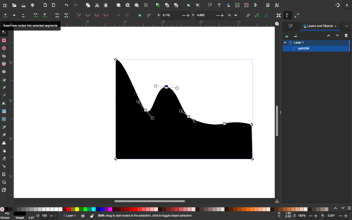
Handy tip: just design one half of the shape, and then duplicate, mirror and combine it into one shape. After playing around with the corners and being happy with the crown-shape, this is the final design:

SVG-PCB
I was excited to be using svg-pcb for this board, and got help from Leo for adding the holes. It involves setting up an exterior path for the actual board and an interior path for the holes. He then used geo.translate to replicate the same hole shape across the x-axis and y-axis: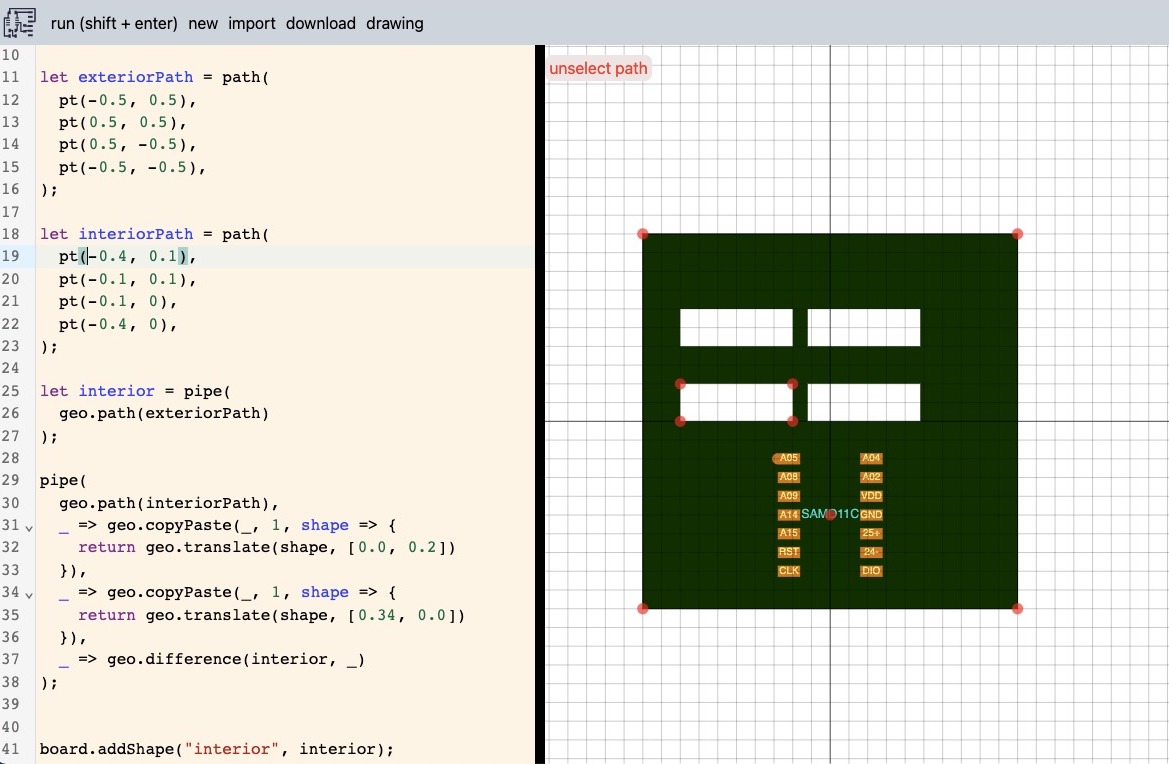
I tinkered around with this for a bit, and then sat down with Quentin to design the flexures in svg-pcb.
First up, we imported the crown image as a svg path:
let crown = geo.pathD([], "m 95.8758,99.96599 c -9.00728,0.49633 -15.715477,34.02654 -21..... z");
// hole parameters
const hole_w = 0.0312;
const hole_h = 0.430;
const hole_n_x = 85;
const hole_n_y = 7;
const hole_w is set to 0.0312, the same size as the 1/32" bit on the milling machine
It is then a set of for loops and if statements that creates the holes around the centre of the crown:
let hole;
var x = 0 ;
var y = 0;

if (do_holes) {
	for (var i=-hole_n_x; i < hole_n_x+1; i++) {
	for (var j = 0; j < hole_n_y; j++) {
		x = hole_w * 2 * i;
		y = j * (hole_h+hole_w);

		// center
		if (x >= -w_center/2 && x <= w_center/2) {
		continue;
		}

		// sides
		if (x < -x_side || x > x_side) {
		continue;
		}

		if (i % 2 == 0) {
		// even number, shift up
		y += hole_h/2 + hole_w/2;
		}
		hole = geo.path(path([-hole_w/2, -hole_h/2],
							[hole_w/2, -hole_h/2],
							[hole_w/2, hole_h/2],
							[-hole_w/2, hole_h/2]));
		geo.translate(hole, [x, y]);
		board.addShape("drill", hole);
	}
	}
}

It was then up to me to design the electronics on the board. I decided to add a phototransistor and 5 LEDs. It was a bit tricky to find the schematic for it, but I eventually used one of Neil's hello.light.45 board as reference (linked here). I also managed to add zero (0!) resistor bridges and I am very proud of myself for that :)
516 lines of code further and here is my final design:
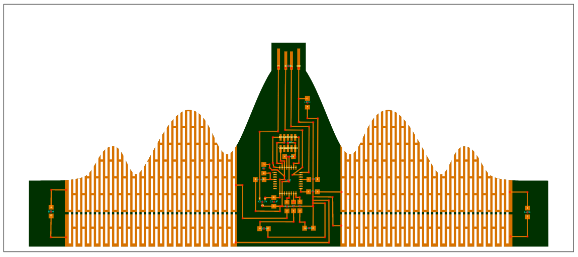
Code file can be found here
Milling
Designing the crown was one adventure, milling it was another.First Attempt
Initially, I had exported two files: one for the traces and one for the holes and outlines. It started out milling perfectly fine: the traces came out beautiful especially since I used Quentin's copper clearing method (settings are further down), but because the holes and the outline were on the same file, the board came loose when the machine started milling the second half of the holes.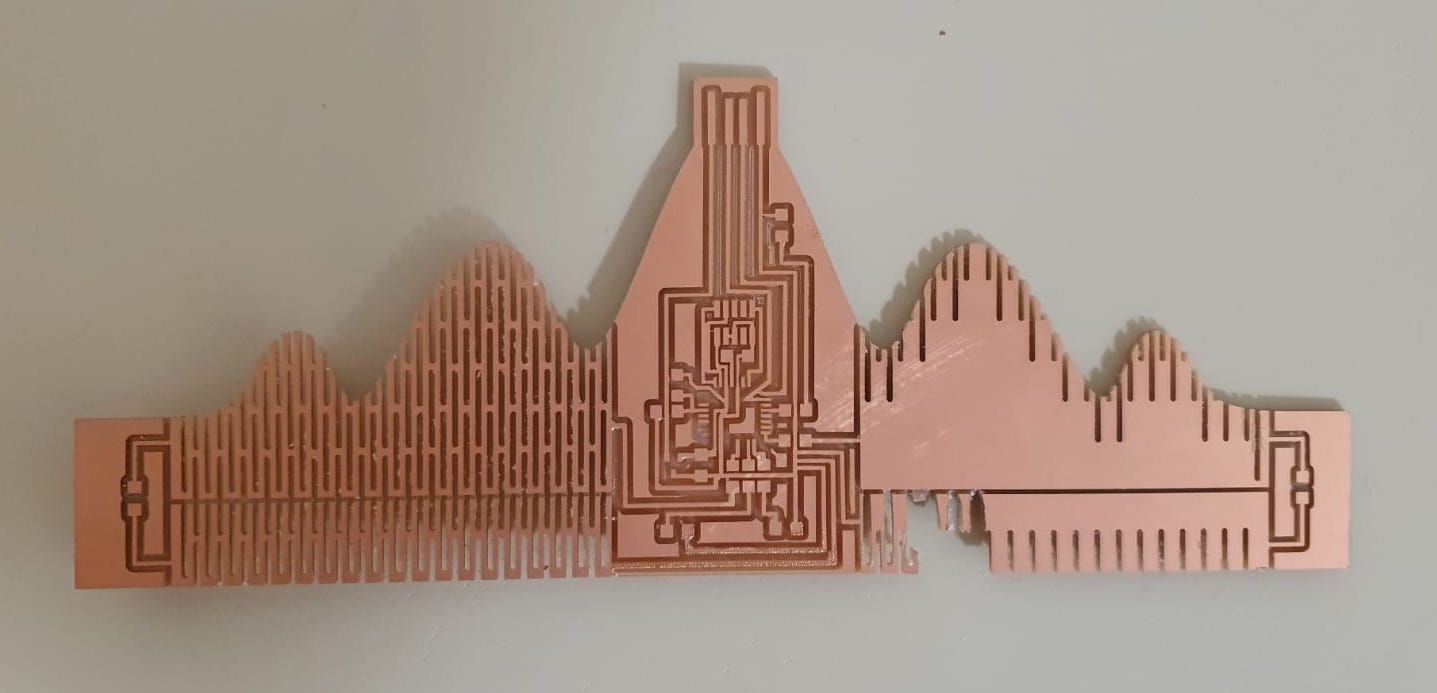
It had milled the holes on the left first, followed by milling the outline second, and then it attempted to mill the holes on the left side of the crown. By that time the board wasn't as secure as it should have been and the tape gave up.
Second Attempt
With Quentin's help, I exported a different set of png's: one for the traces, one for the holes, and one for the outline. Again, everything milled perfectly fine until it got to the holes.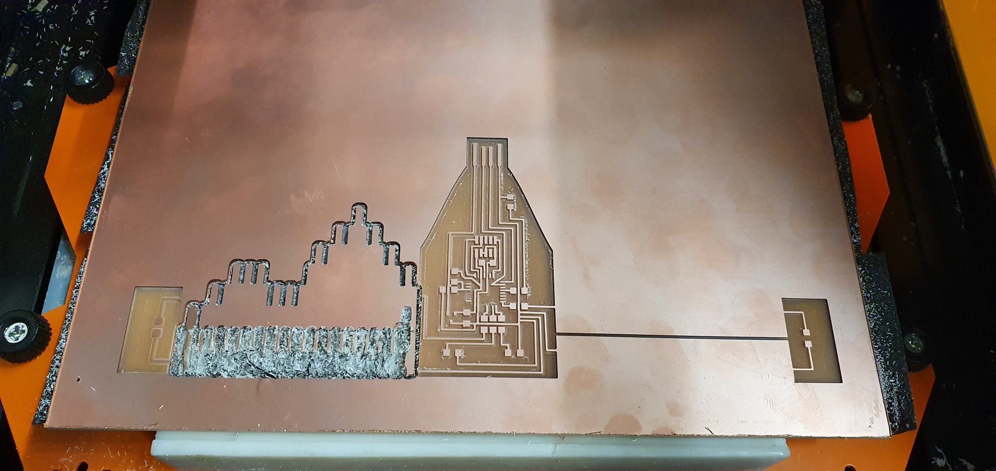
I used the same settings for the holes as I would for the outlines (white for the shapes to be milled on a black background). I started experimenting with different values for the offset, but to no avail. I then had a lightbulb moment: what if I invert the image to be black on white, instead of white of black? And it worked! Confident that these settings would work, I set out to mill again.
Third Successful Attempt!
I ended up having four files to mill:1. The traces
Using the standard settings and 1/64" bit, except for an offset of 2.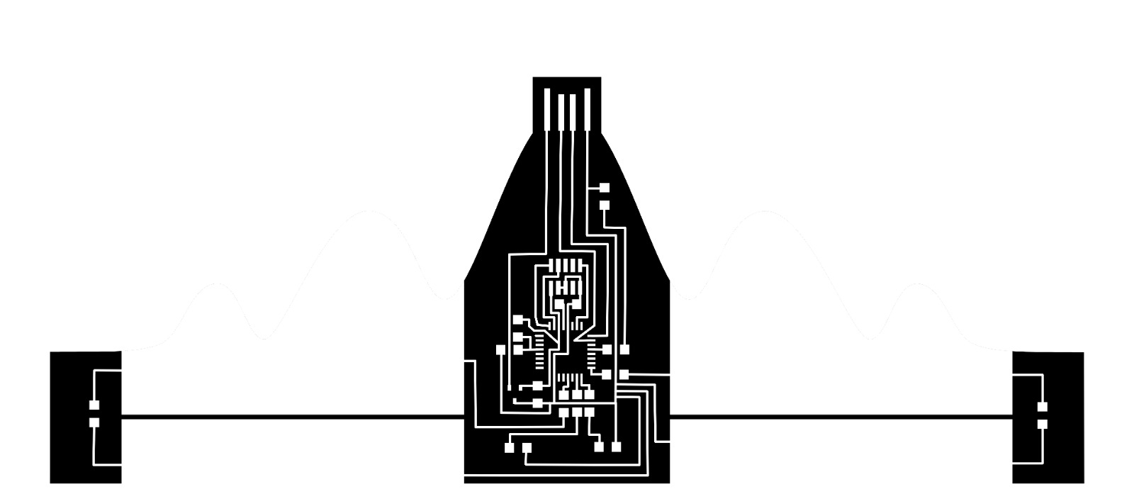
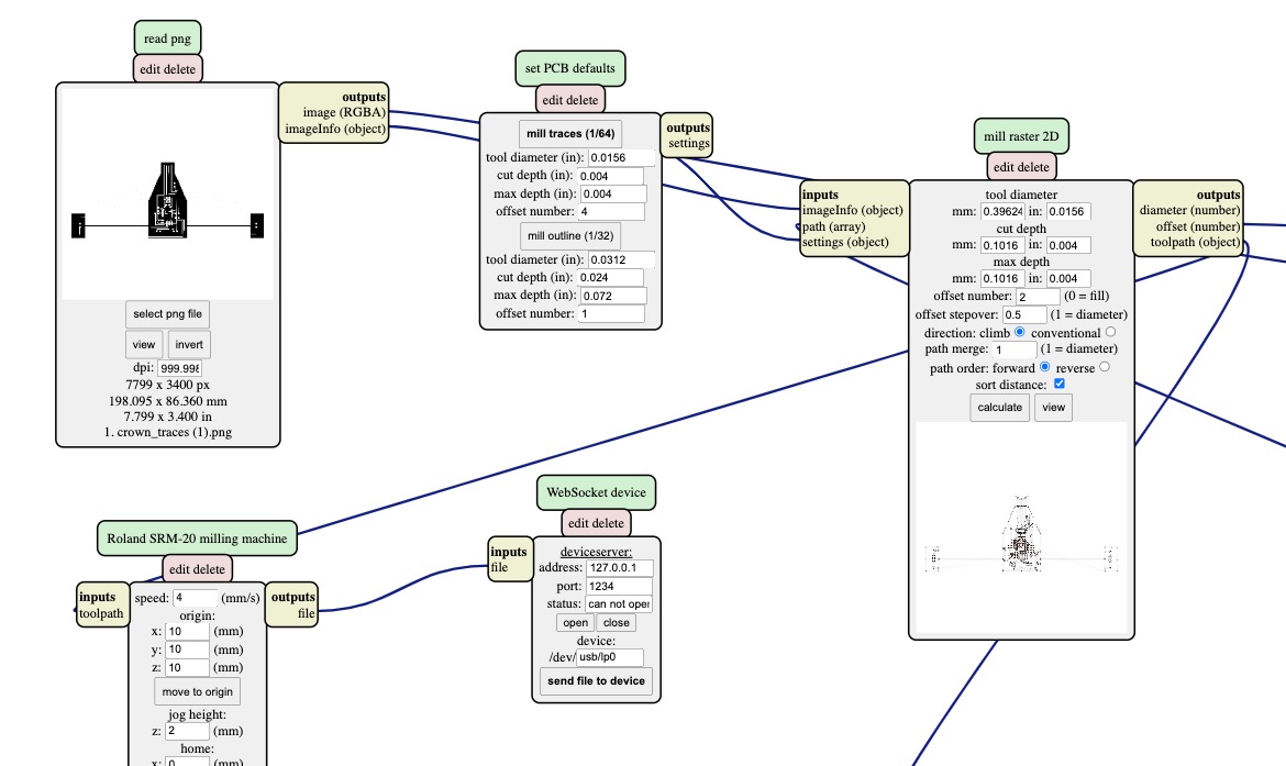
2. Copper clearing
Using the same image for the tracing, but with the 1/32" bit, an offset of 0 and a maximum cut depth of 0.1mm (or 0.004 inches).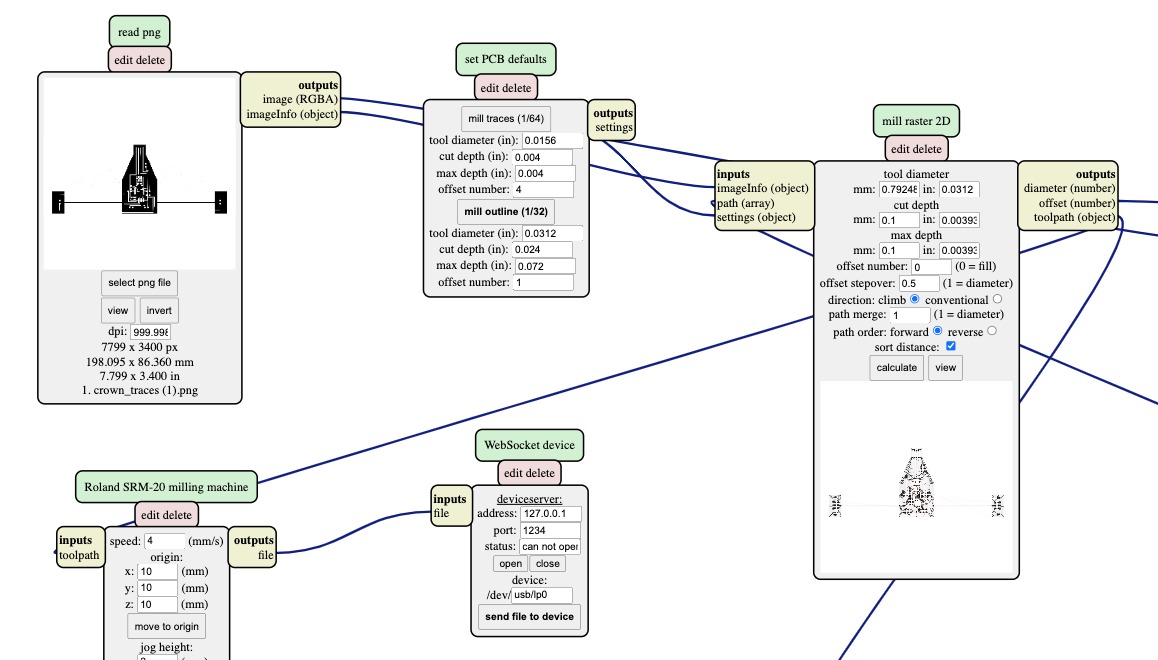
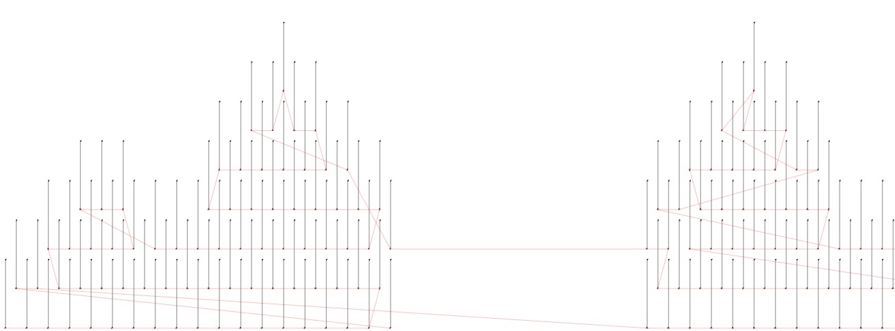
3. Holes
I used a black on white background image, which allowed me to mill single paths the same thickness of the bit. I used 1 offset, 0.4mm cut depth and 1.6mm maximum cut depth.
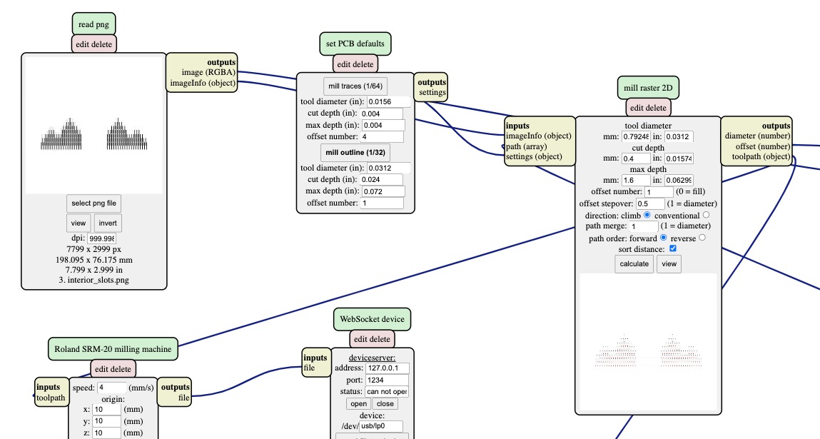
This is how mods would show it, and the single lines mean that the machine will make a single pass horizontally:
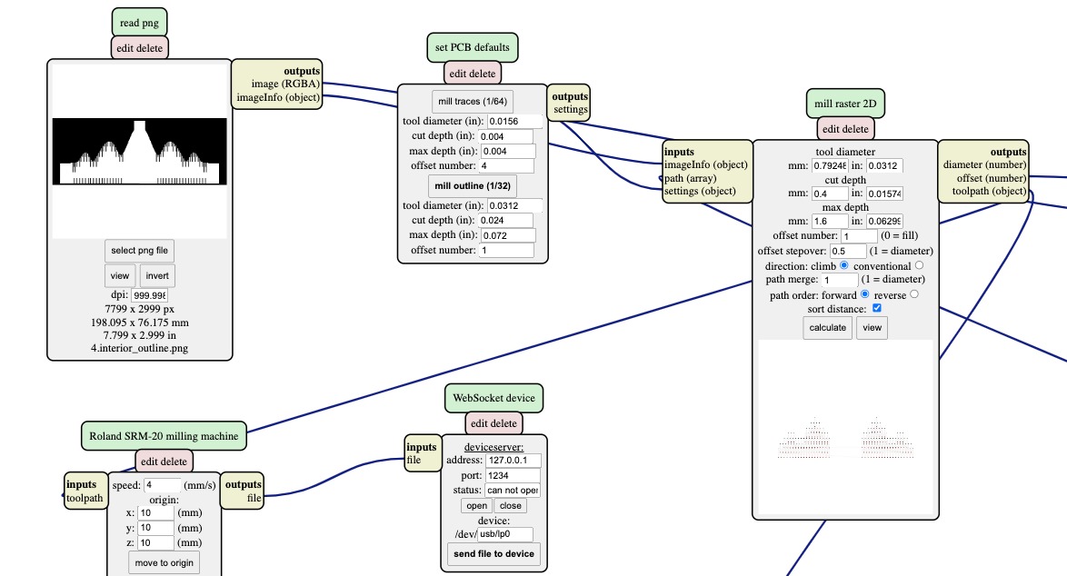
4. Outline
This time using a white on black image, and the same settings as step 3
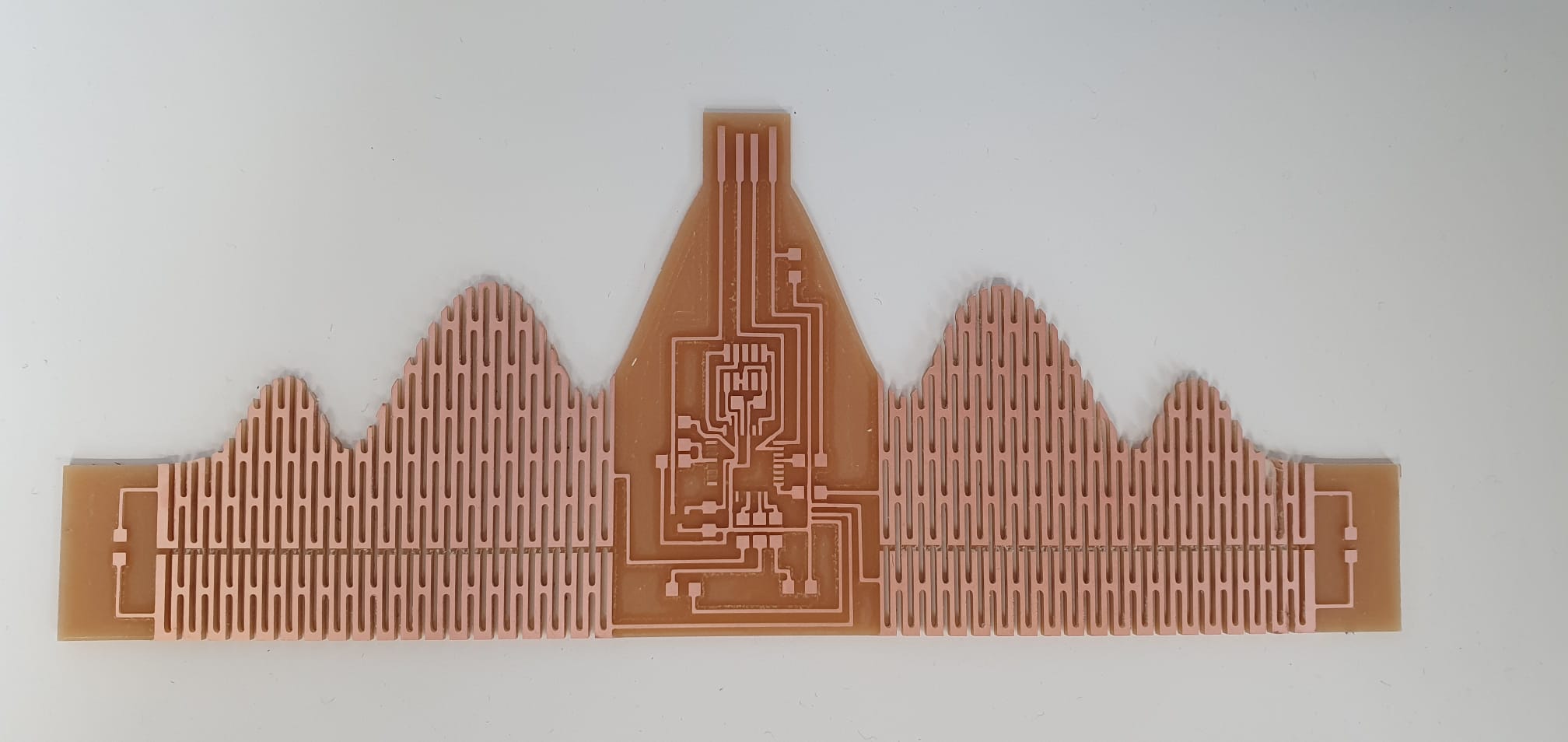
Finish
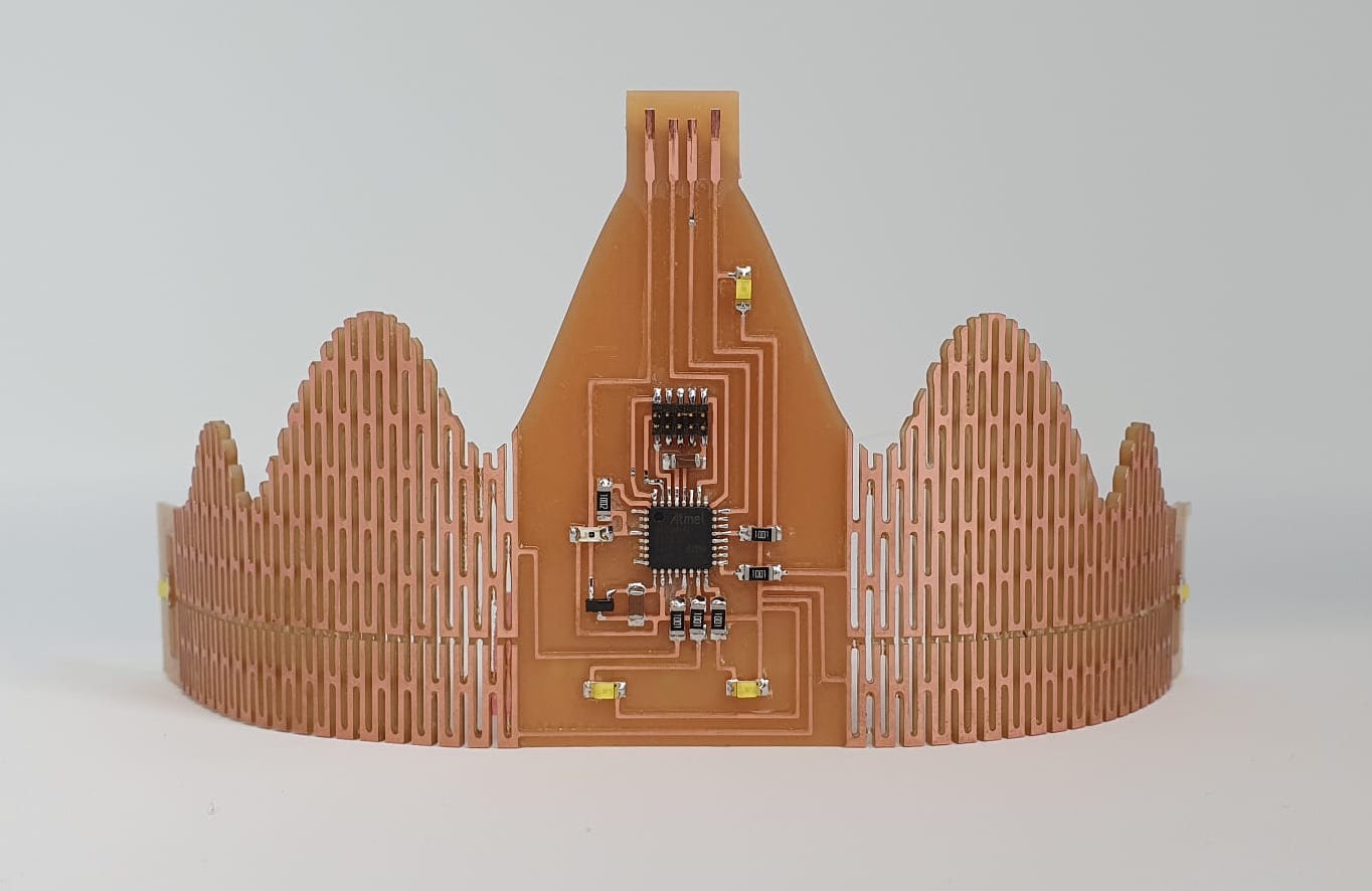
And look at how it came out: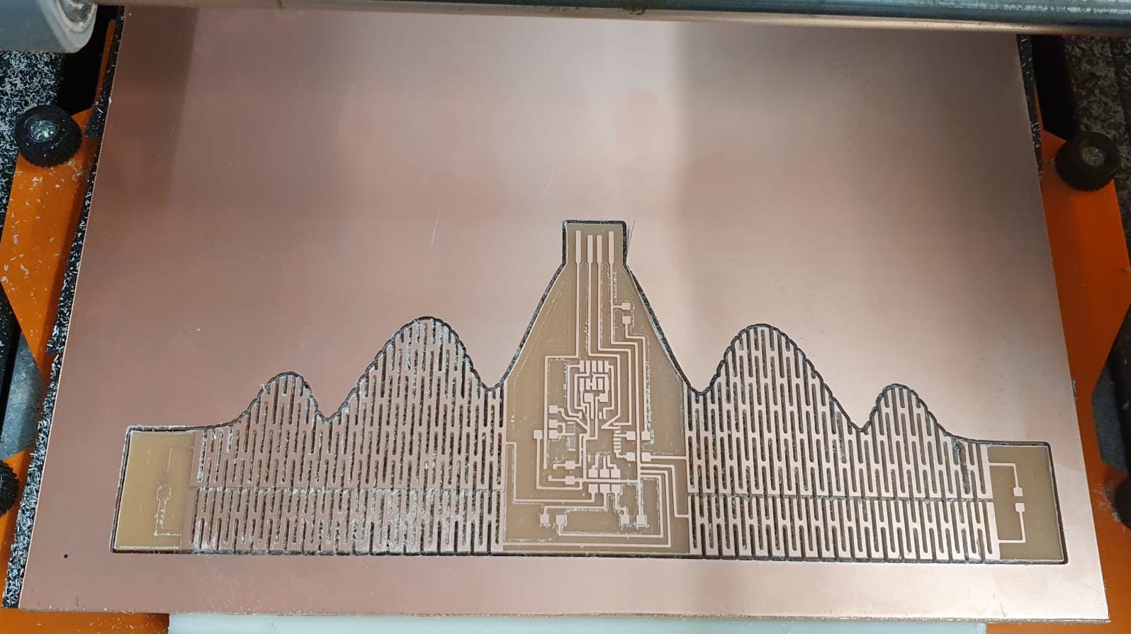
Beautiful!
Soldering
I performed the most delicate soldering I have ever done and I am very happy with how it came out: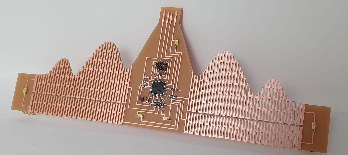
Of course I had to try it on!

Arduino
My board openocd'ed the first round! I reused a program that Quentin had written that utilises the phototransistor. Based on how dark it is, the LEDs will blink!
#define N_PIN 5
#define PIN_PHOTO 3

int pin_leds[N_PIN]= {22, 16, 10, 14, 15};

void setup() {
  for (int i=0; i < N_PIN; i++) {
    pinMode(pin_leds[i], OUTPUT);
  }
}
void loop() {
  int value = analogRead(PIN_PHOTO);

  if (value > 900) {
  for (int i=0; i < N_PIN; i++) {
    digitalWrite(pin_leds[i], HIGH);
    delay(100);
    digitalWrite(pin_leds[i], LOW);
  }
}
}
And here it is flexing:
Charlieplexing
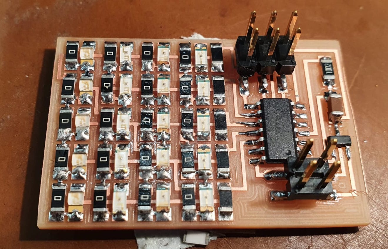
For this week's assignment, I wanted to continue experimenting with LEDs. Neil showed a beautiful example of charlieplexing in class, which is a way of controlling an array of LEDs without using too many pins on the chip. I took the hello.array.44 board example (linked here) to tinker with.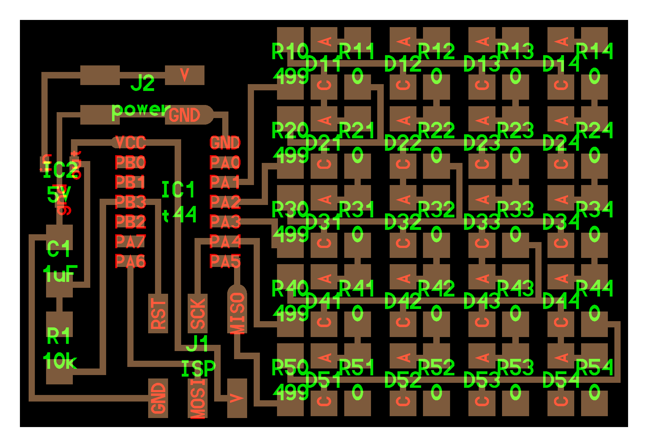

It has 20 LEDs and 25 resistors, and I am always up for such challenges :)
I milled the board using the same settings I used before with the copper clearing, and the result is a beautiful little board:
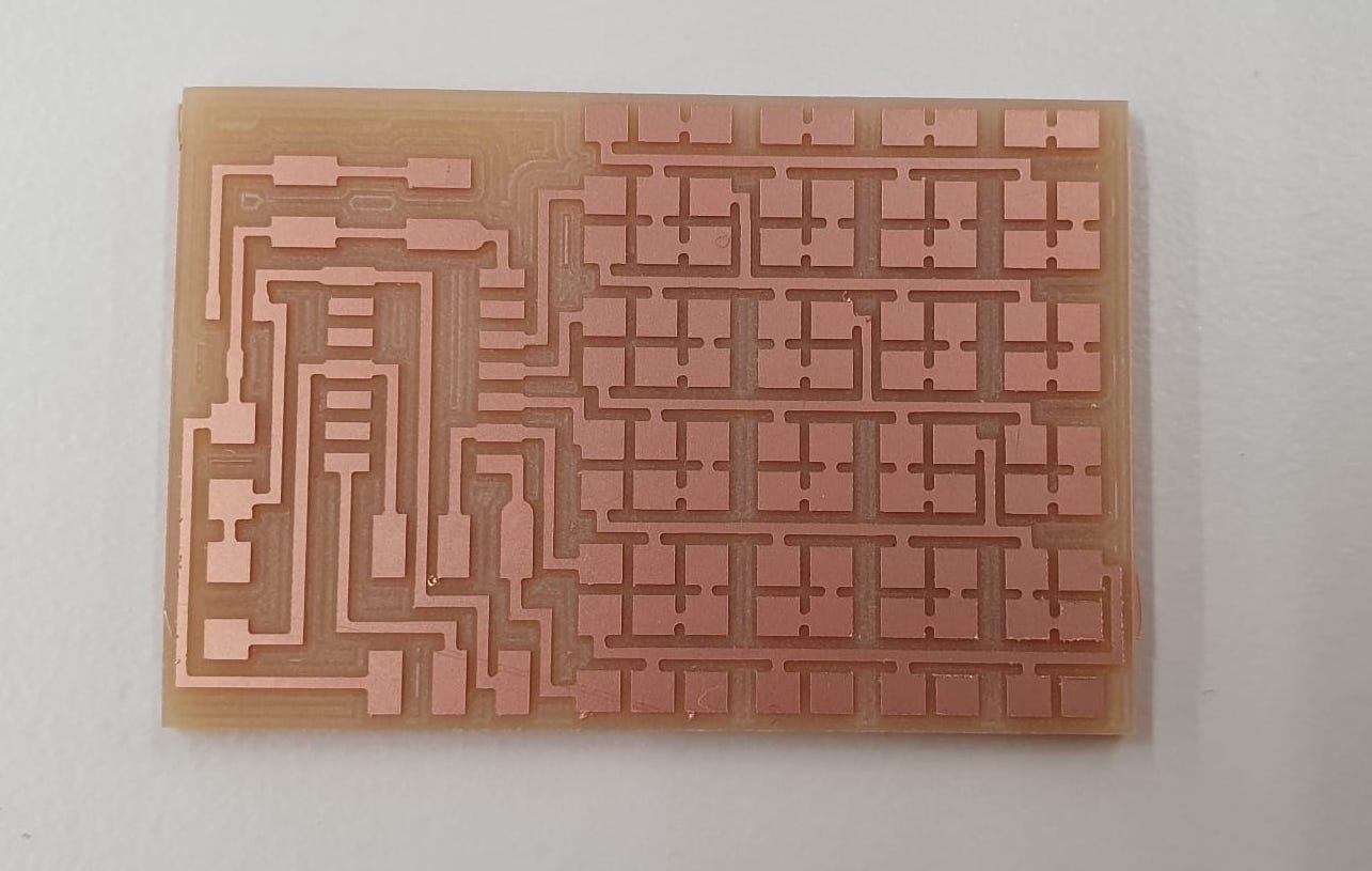
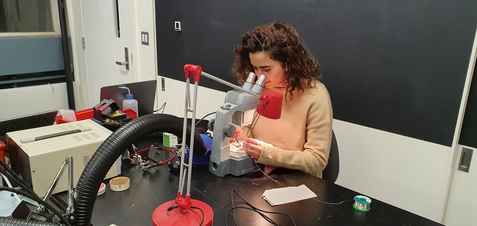
This board was also quite delicate, and I found the whole process of soldering it to be quite meditative.
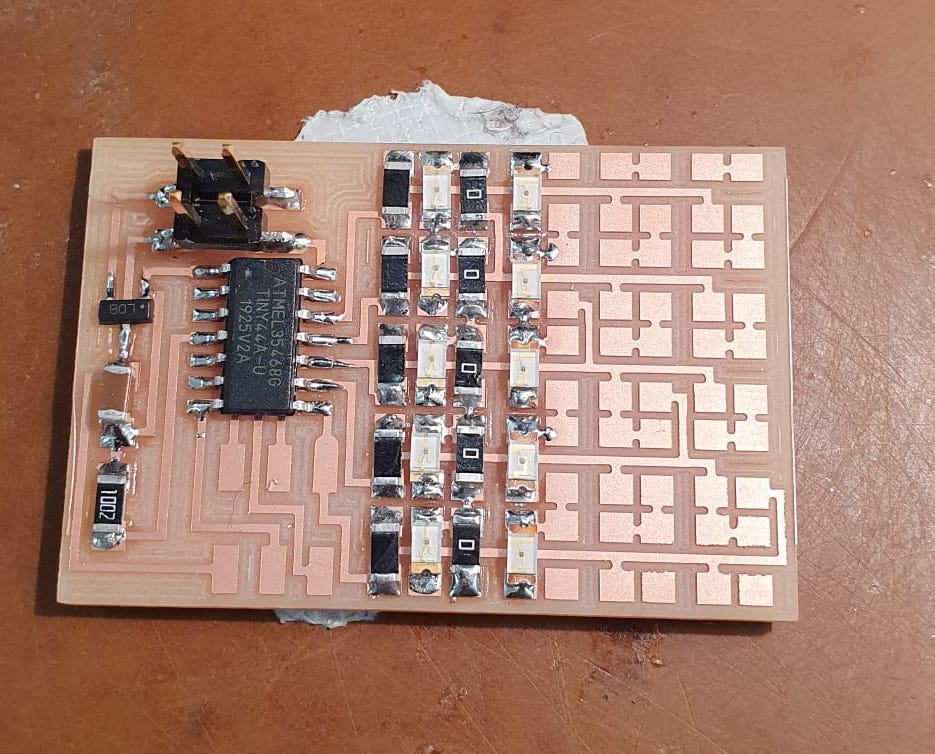
I soldered everything without using flux, which I found out is quite a flex.
And after a full hour and a half, it was all done!
On to the programming!
Arduino
With the help of Chris Zhu (TA) I installed the correct ATTiny library from this link. Read the Installation.md file first, and then the Programming.md file.The ATTiny44 will be programmed via ISP so after I got everything installed, we got an Arduino and wired everything accordingly. Here are the instructions (from the programming.md file I referenced earlier) on which pins on the Arduino to connect to which pins on the header of my board:

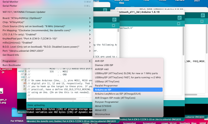
In the settings, I selected "Arduino as ISP" as the programmer.
It bootloaded successfully!
However, when I tried to upload code to it, it didn't do that so successfully:
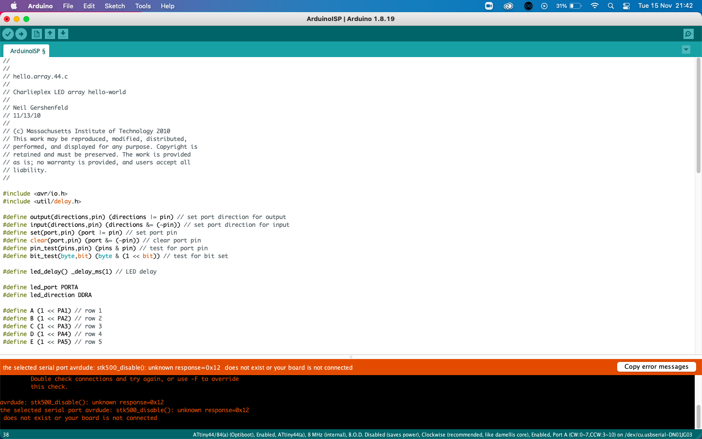
I googled a bit but couldn't figure it out. I also accidentally touched the capacitor and burned my finger, so there is definitely something fishy going on.
Quentin had a look at it and advised me to remove the 5V voltage regulator, as it seemed counterintuitive to have it regulate the same amount in power supply (also 5V). So I removed it and added a 0ohm resistor instead. Everyone's fingers were left unburned when I connected it to the Arduino again.
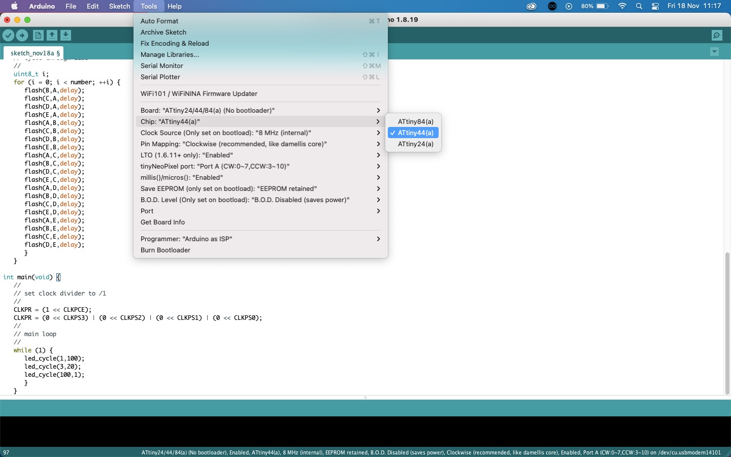
This time we selected the ATtiny24/44/84(a) as a board with No Bootloader (which is opposite to what Spence's guide instructed, it recommeded choosing the Optiboot option which is what I did previously).
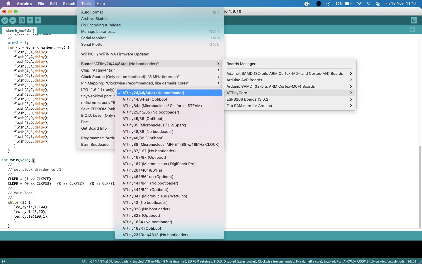
And don't forget to select the correct board!
The rest of the settings should be good, but again select 'Arduino as ISP' as the Programmer. I uploaded Neil's code and it worked!
Artificial muscles
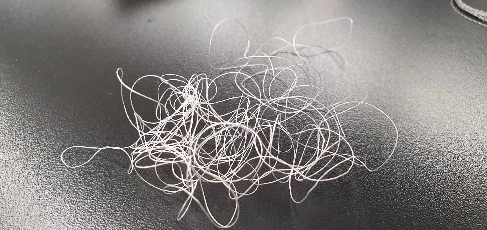
Jack Forman gave us a wonderful recitation on artificial muscles using Liquid Crystal Elastymer (LCE). Having worked with fabrics a lot, I was fascinated by the posibility of adding movement to textiles. I got a sample of the LCE as well as some instructions from Jack himself on using conductive thread that has a polymer core. I used this article as a guide.At Harvard, we didn't seem to have silver conducted thread with a polymer core, so I visited MIT over the weekend to get my hands on the thread. I happened to bump into Ozgun who gave me not just one, but three different kinds of conductive thread! First we have the LCE:
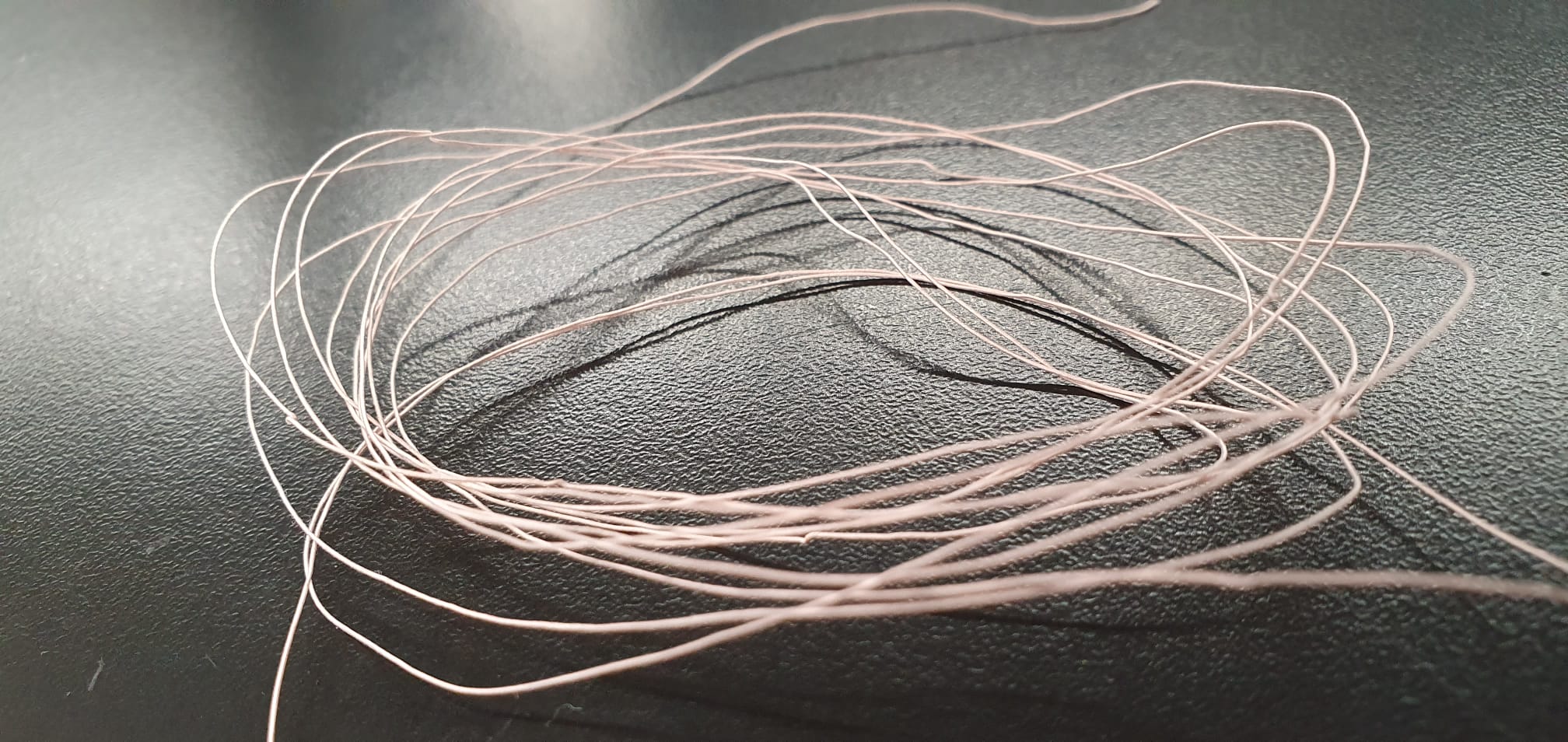
The Litz wire which has a conductive core and is the thread that was found to be the best to use:
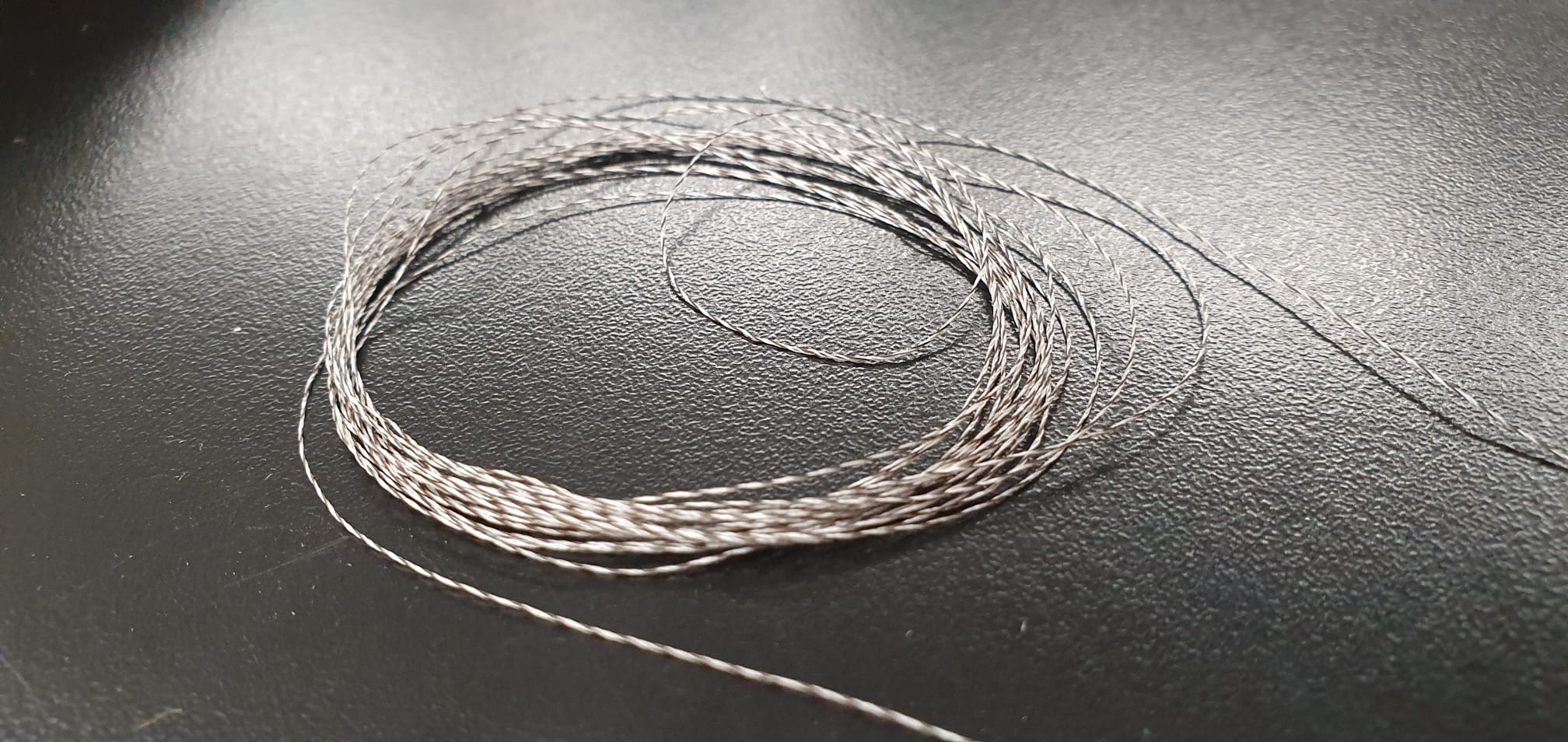
Some wire optim nichrome, which is a very delicate type of thread and conductive:
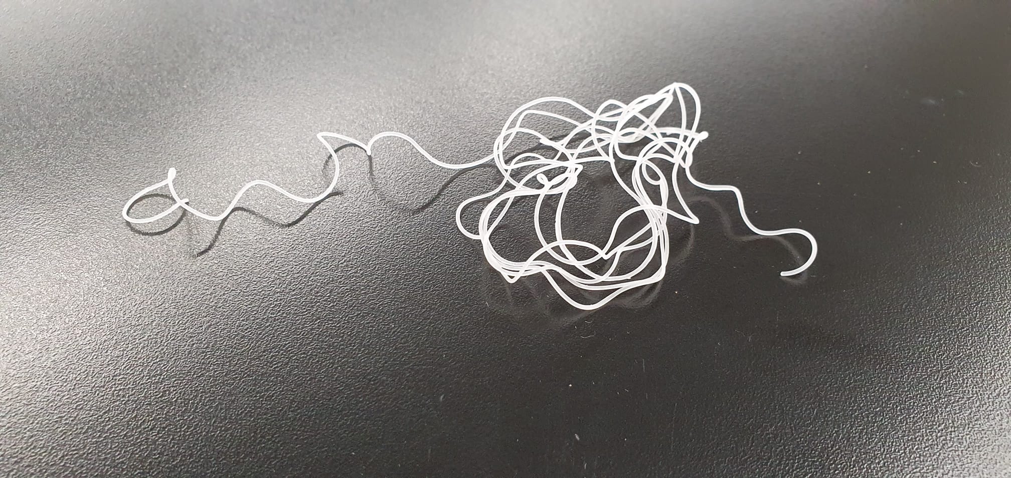
And finally, some other type of thread that I don't have the name of:
I first coiled each type of thread around a piece of LCE:
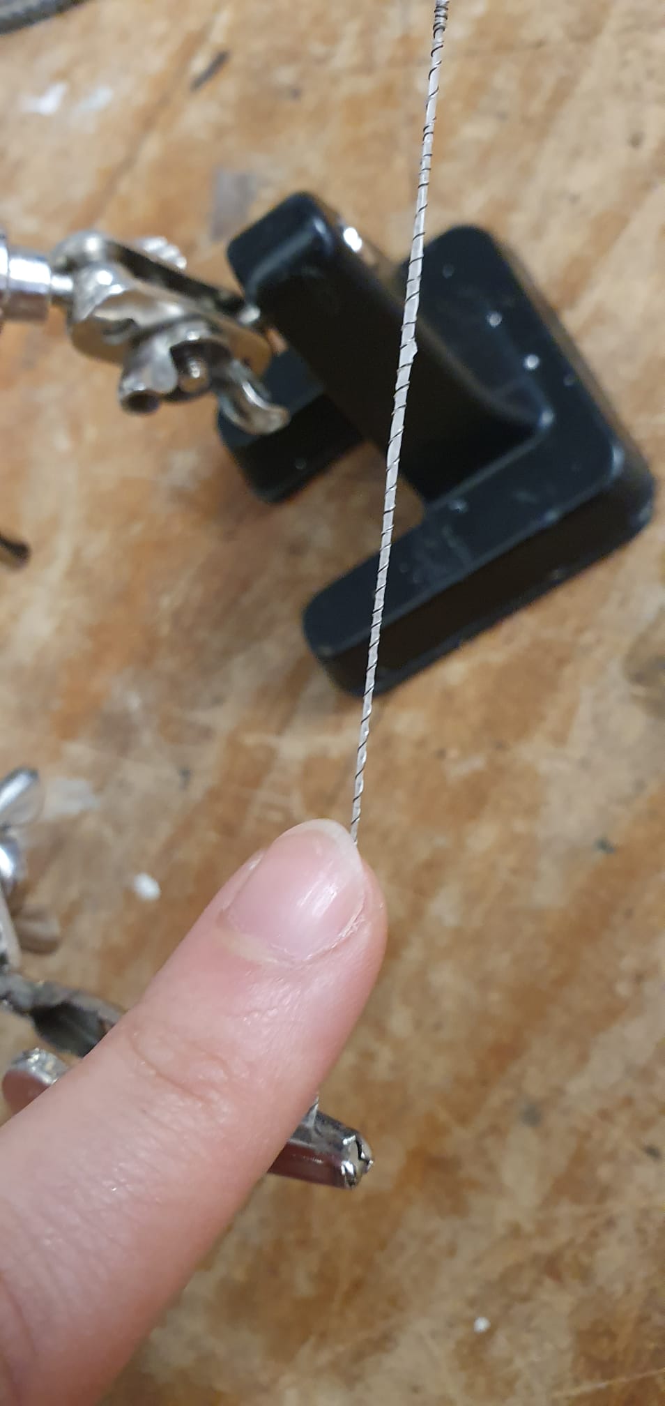
For some of the threads, I had to expose the metal core at both ends so it conducts when I apply current through it.
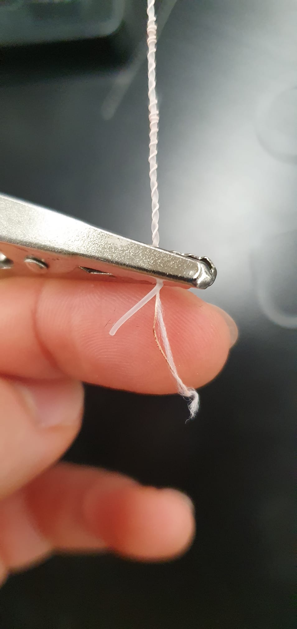
I kept the LCE in place using the soldering puppets. In the end, they looked like a musical trio:

I then applied voltage to it using crocodile clips. I started at 0, and used increments of 3V. I went up to 32V but the thread didn't contract. I couldn't apply any current through it, and checking with a multimeter there didn't seem to be any connection.
I tried the heatgun instead and set it to 100F. It was pretty cool to see:
I need some more time to experiment with this, and try to find thread that reacts at lower temperatures, ideally body temperature. I also visited Jack Forman at MIT who quickly figured what the issue was: alligator clips don't allow for the best connection and I should either solder a jumper cable or use finer connector clips (like the ground clip on the oscilloscope).