Week 2
Computer-Controlled Cutting
From diving deep into git and Fusion360, to getting enlightened by Alfonso's CAD wisdom during office hours and spending late nights at the Harvard Lab: this week was a rollercoaster!
Group Assignment
Claire and I wanted to figure out the optimal settings for the laser cutter, including the speed, power and kerf. We arrived at some interesting conclusions, but first the process of getting there.
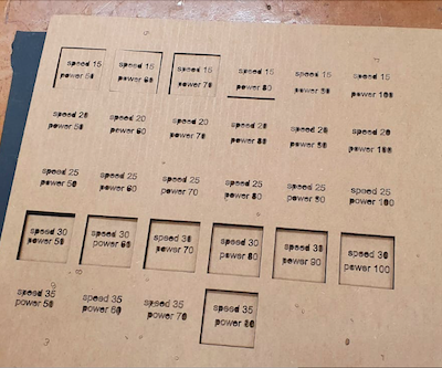
Claire designed some neat squares in Fusion, and transferred them to the LightBurn software. We set each square to a different speed and power. The first time we ran the cut, the machine started acting strange:
- it cut the squares in a random order
- it went over some squares twice
- it got stuck on one specific square and started to make multiple passes on the same edge of the square
However, no need to panic and purchase a new laser cutter because we figured it out:
- to cut in a specific order, you can set the order of each cut in the right hand panel (see image x - insert image)
- to have the laser cutter go over a line once, set the pass count to 1 in the right hand panel, and make sure you have one (1) coloured layer
- use 'line' instead of 'fill': fill will try to cut away the entire square/shape
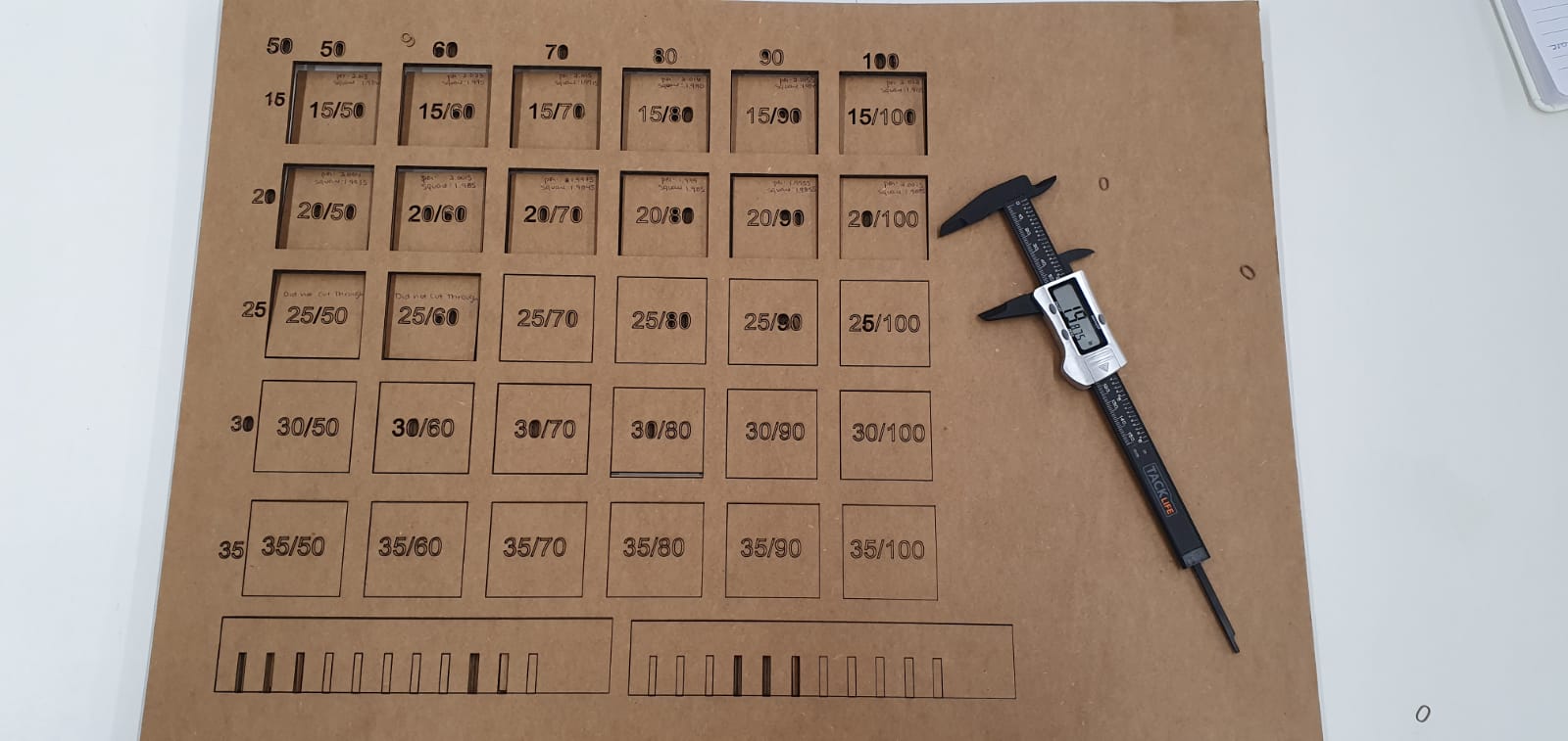
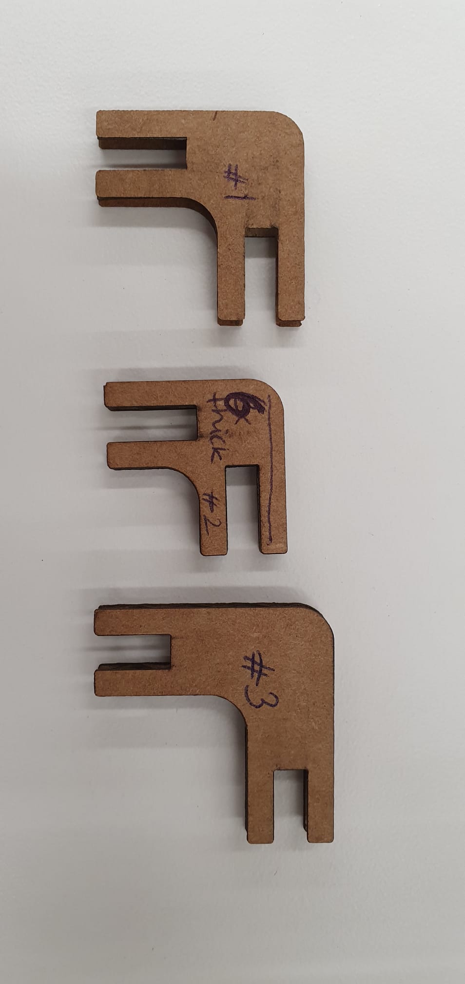
We punched out the pieces that were punchable, and (1) measured each square, and then (2) measured its silhoutte. The difference between the two would give us the kerf. In the image below, we have positioned them to be from biggest kerf to smallest kerf, left to right.
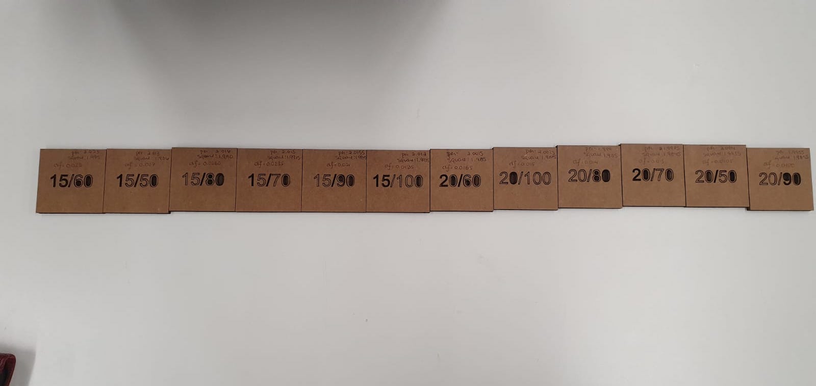
A major finding was that anything with a speed of 25 and up didn't cut through, regardless of the power setting. This is interesting, given that the recommended settings are 30 speed and 60 power. A possible explanation could be that the laser cutter needs to be recalibrated and/or reconfigured.
Another interesting conclusion we arrived at, was that the biggest kerf is at 15 speed and 60 power: the laser cutter burned away 0.0218 inches in total off the edges, which is equivalent to 0.7112mm. On the other hand, we found the smallest kerf to be at 20 speed and 90 power, with a kerf of 0.0100 inches, equivalent to 0.254mm. Important note is that these numbers need to be divided by 2 to find the kerf for each side. However, similar to the point I made in the paragraph above is that our findings could have been influenced by a poorly calibrated laser.
Construction Kit
Learning Fusion was tricky at the beginning, mainly because I couldn't find Youtube tutorials that were applicable to my project and easy to understand. There is a beautiful Dutch saying: "Door de bomen kun je het bos niet meer zien", which literally translates to "Because of the trees, you can't see the forest anymore". That pretty much sums up my initial CAD journey this week, because I fell into a deep Youtube CAD rabbit hole (I do have a whole series now of dovetail joint design if anyone is interested).However, Alfonso was incredibly helpful and showed me the ins and outs of Fusion within minutes (!) and I was able to design my construction kit in its entirety while in his office.
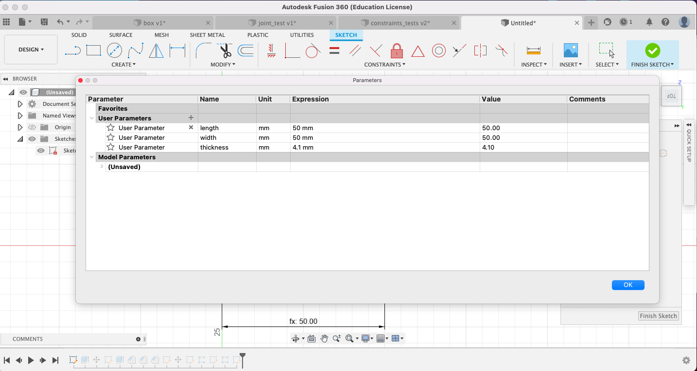
Setting parameters proved to be incredibly time-saving and efficient, just as Neil explained. For example, I initially set the thickness of the cardboard, which affected the width of the slots, to be 4.5mm, but after the kerf experimentation, we found that 4.1mm provided a much more snug fit. Because the cardboard thickness was set as a parameter, I was able to change it with two clicks, and the rest of the design adjusted accordingly. Genius!
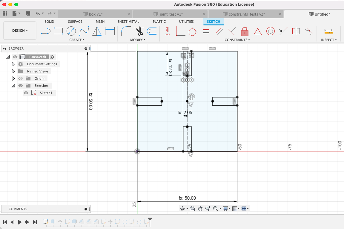
This is how the square looks like:
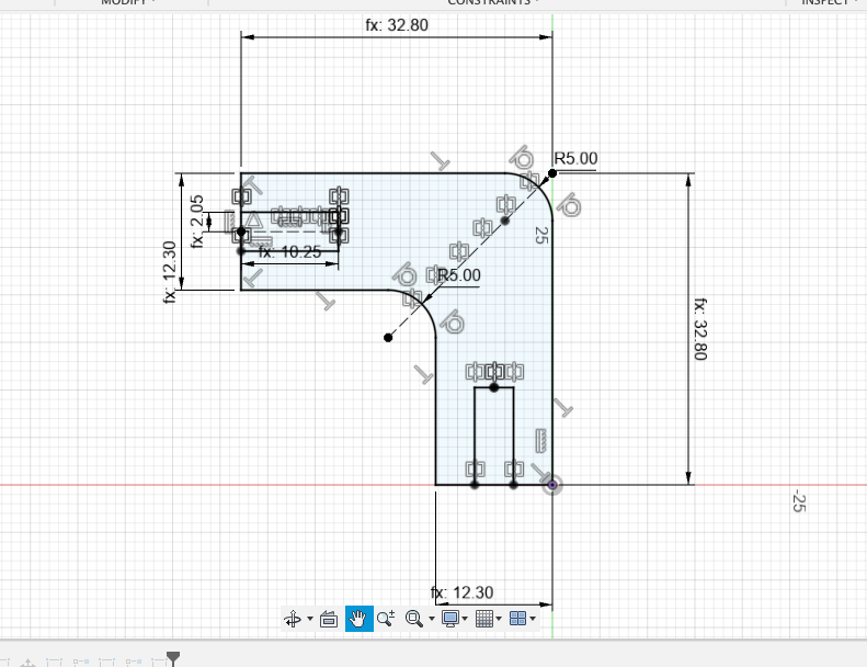
For the connectors, Alfonso had a very clever strategy: he designed half of the connector, drew a construction line diagonally and then reflected the shape across a 45° angle. Doing as little CAD work as possible is the goal!
It was then time to test out the connectors. I initially set the connector sides to be six times the thickness of the cardboard, just to keep everything constant. However, when I test cut some squares and connectors, I found that the slot of the connector was wrongly sized: when I tried to join two squares together, one square would slot in perfectly, while the other wouldn't be able to slot in fully and would bump into the first square.
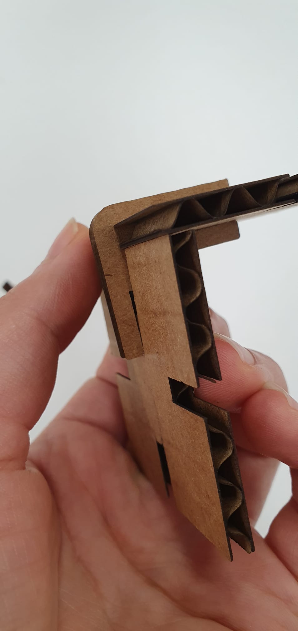
I intially thought of making the connector smaller, but the lack of sleep might have impaired my judgement, because that was a terrible idea. With the help of PK I realised that I should make my connectors longer, and that worked out really well!
After I finalised the design of the connector (which, again, took just two clicks thanks to parametric design!), it was time to laser cut. It was a pretty long run time, and I maximised cardboard space efficiency. However, more than half of the shapes didn't cut through properly, even though I used the most efficient setting (according to our calculations) of 20 speed and 90 power. There is definitely something wrong with the laser cutter, and we reported it back to the lab manager. Nevertheless, the ones that did cut through came out just fine!
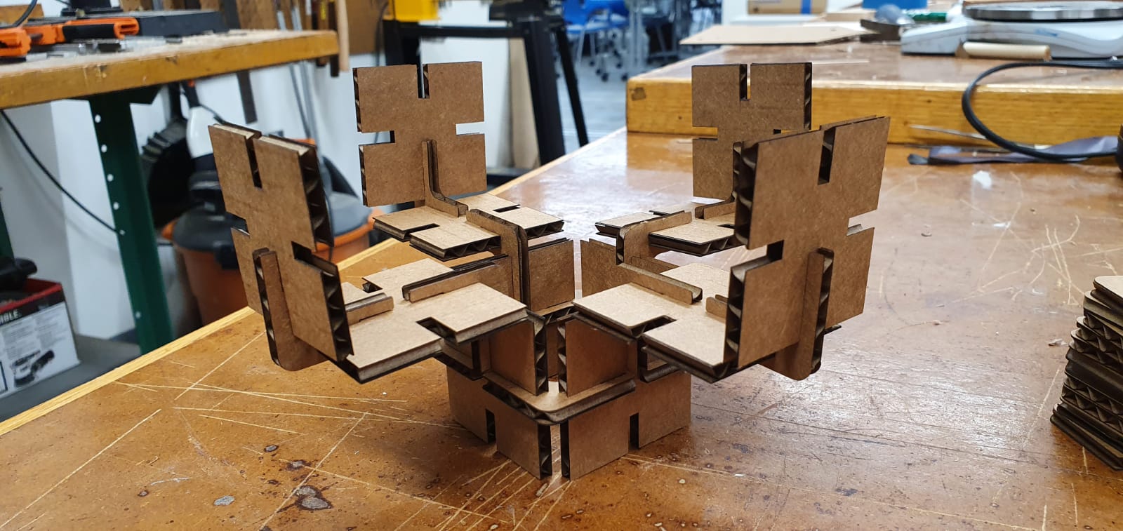
Here is the kit:
Vinyl cutter
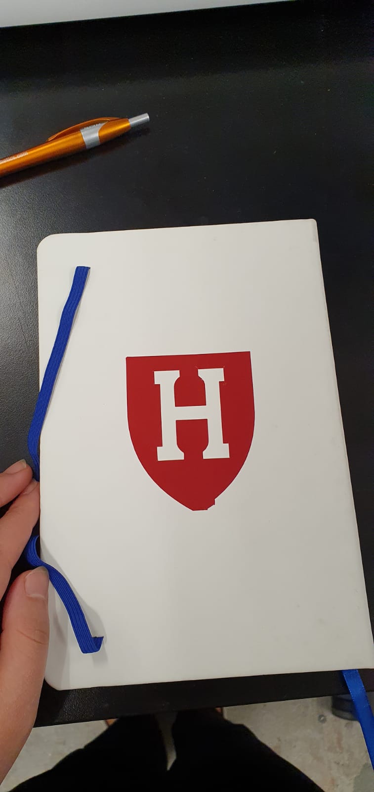
For the vinyl cutter task, I decided to make a pretty generic sticker with the Harvard H logo in (close to crimson) red. It wouldn't print at first, and with the help of Nathan, we figured that the Terminal wasn't open, and the mod wouldn't run as a result.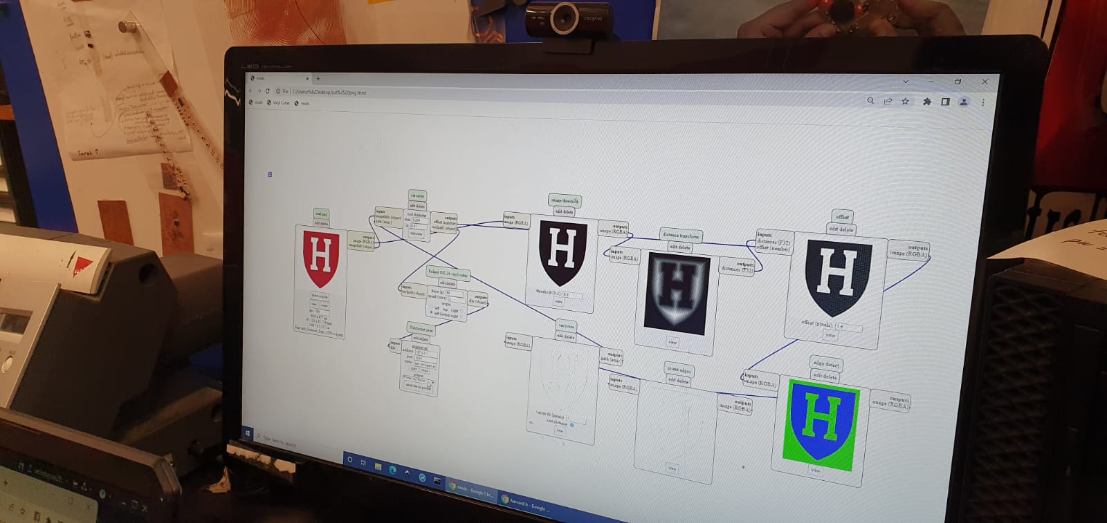
Other than that, it was pretty straightforward and very fun to make stickers. I stuck the sticker on my HTMAA notebook!