Week 3
Electronic Design
Milling, PCB's, soldering and more!
This week's topic was about electronic design, and as always, we started off with with a full-on crash course by Neil, followed by Jack Read (recitation),
who taught us all about Ohm's law, forward voltage, capacitance and inductance.
Leo McElroy and Nathan Melenbrink also did an incredible job guiding us through PCB milling and soldering on Thursday during the weekly group training.
I took countless boards apart and soldered them back together to get a good grip on soldering, and felt ready to start making my own board.
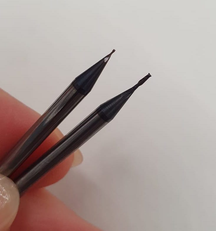
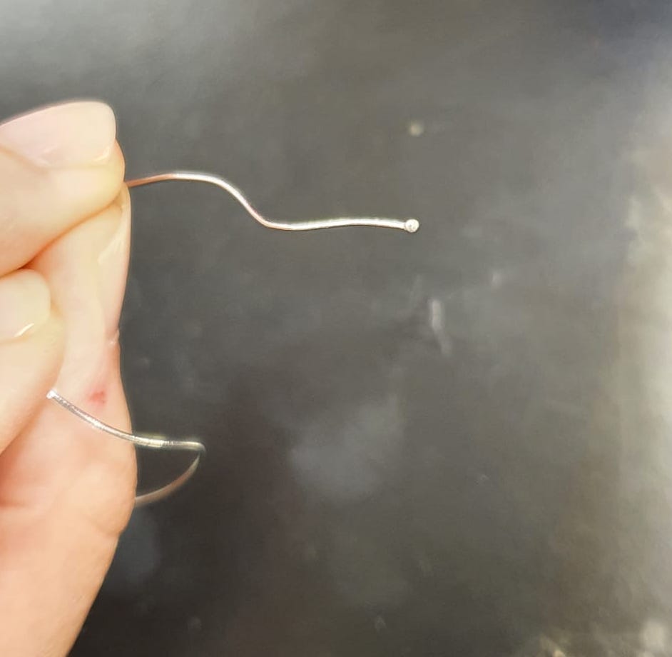
I first checked the 1/64 end mill to make sure it's intact. Spoiler alert: it wasn't! Here is the difference
between a severely used (left) and new (right) end mill.
After carefully replacing it, I used the mods program and the Roland milling machine to make the first PCB. However, first tries are (almost) always doomed, and this was no exception.
I had positioned the x-axis too close to the edge of the plate, and I was afraid that after getting the outline in, the thin strip on the edge might fly off and damage the machine.
So I had another go, this time positioning the x- and y-axis to a nice big spot on the plate, with plenty of space around it. But to no avail, because after getting the traces in,
I realised that the plate was slightly skewed due to unadhering tape underneath it, so I stopped the machine.
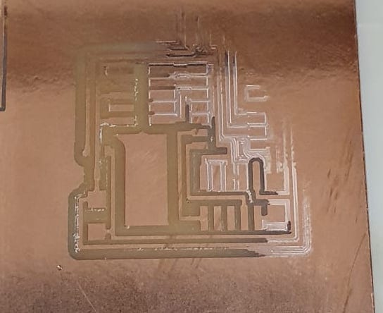
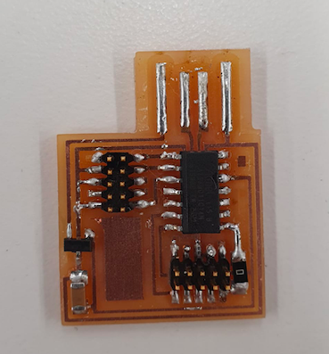
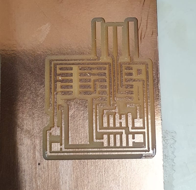
But you know the saying, "Third time's a charm"! I got a new plate, aligned everything correctly and got a beautifully milled PCB. On to the soldering!
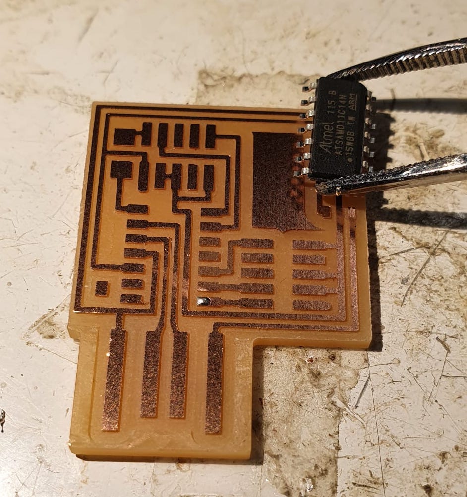
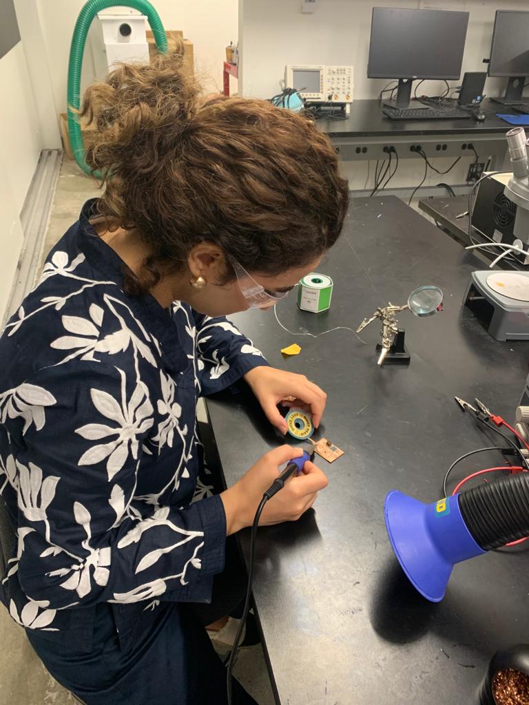
My peers helped me find all the pieces (and I passed on the wisdom to my other peers, too), tinned the soldering iron tip nicely, and scraped off the copper around the USB connection. I started soldering the SAMD11C chip first.
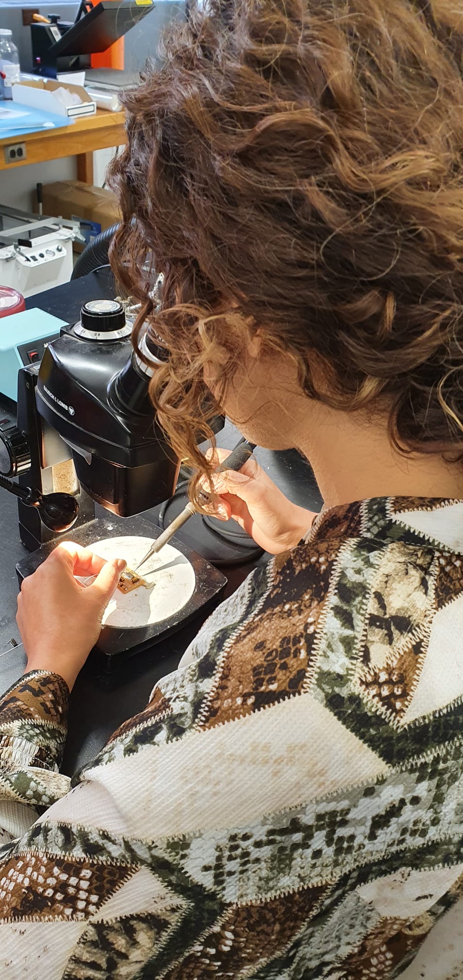
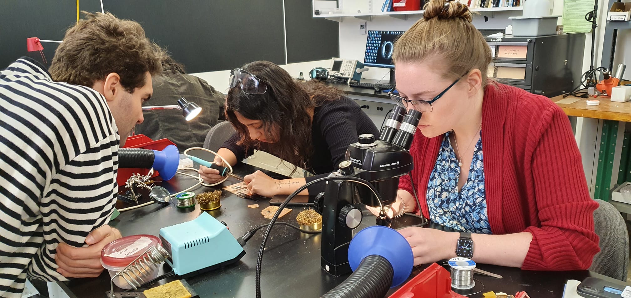
Thanks to Ibrahim's brilliant suggestion, I used the microscope to get a closer and more precise look at my board when soldering, and it definitely helped! I still need to finetune my soldering skills, but practice makes perfect.
Interestingly, during the soldering I kept on getting accumulations of lead at the end of the solder, coined 'blobs'.
Turns out, I had to increase the temperature a bit, so that the solder wouldn't freeze up so fast. Again, practice will make perfect!
The teeny tiny components were fun to solder, but took a lot of time too. Leo suggested checking each connection with a multimeter to make sure the joints are well soldered. I checked my board and everything seemed to be well connected.
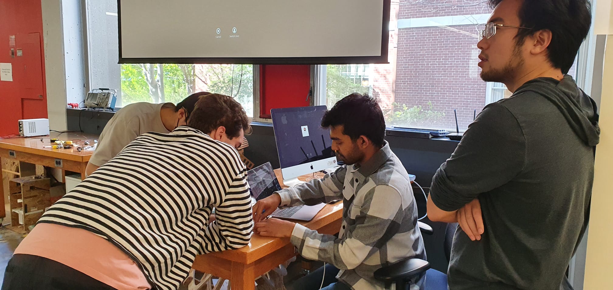
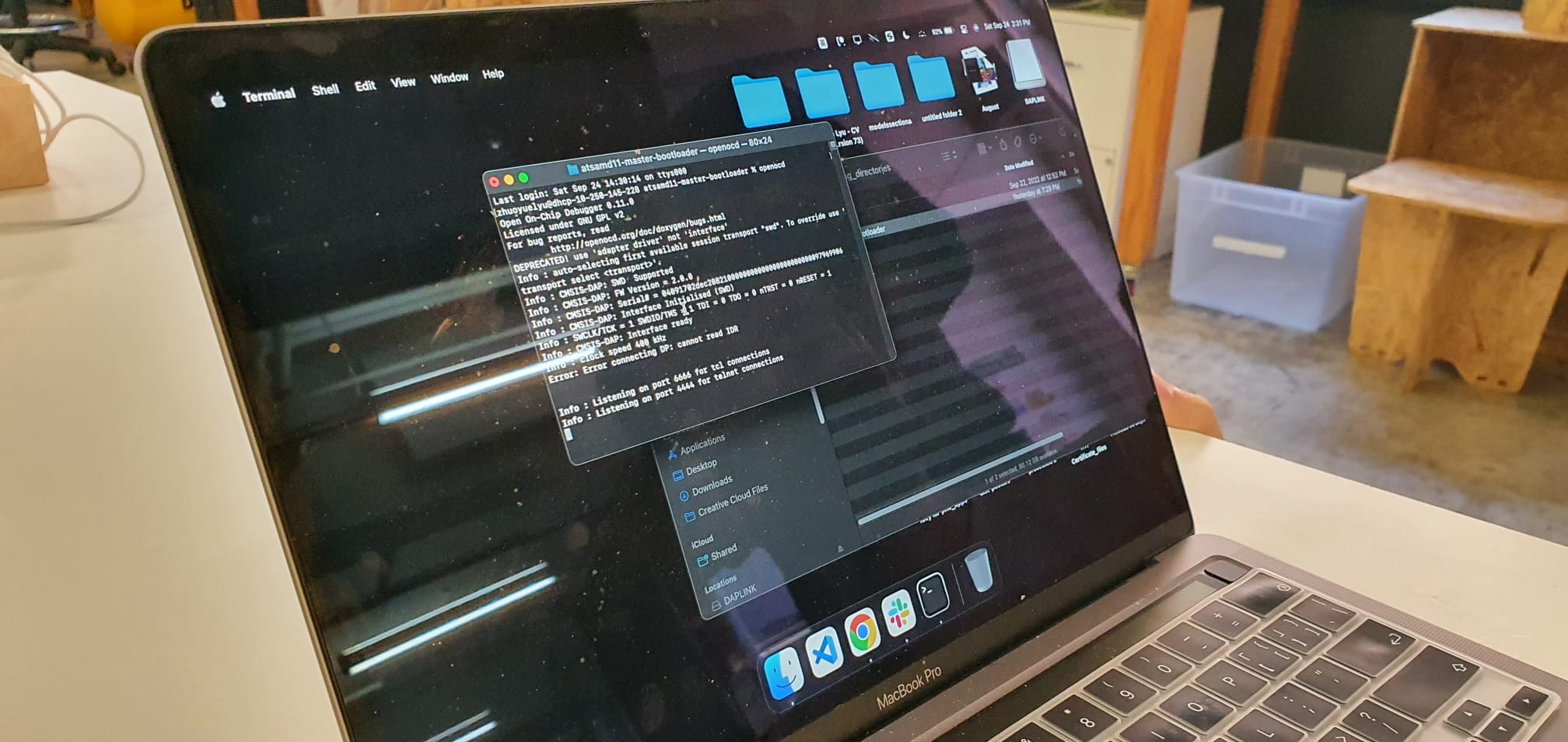
However, when it was time to program the board with another master-board, it threw error after error. What ensued was a 2-hour troubleshooting session with Suvin, Zhuoyue, Treyden, Taili and Danny. We figured out that there might be a problem
with one of the connections, and mainly the shims (they were too blobby and wavy), so I went back to the soldering table.
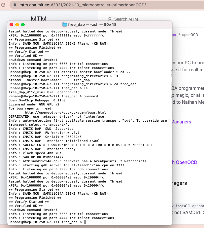
When I got my board fixed and tried again with Zhuoyue, it worked! I hadn't felt this happy since I got into the HTMAA class.
Now that my board was all programmed, I could help others! Not an expert yet, but an educator and Ed School student ;)
Having worked with e-textiles and sewable electronics before, I would have absolutely loved to use the Brother embroidery machine to embroider a circuit. Inspired by the article that Neil shared during the lecture http://cba.mit.edu/docs/papers/00.07.E-broidery.pdf
and the recitation session that Camron led for the 2021 cohort (https://gitlab.cba.mit.edu/camblackburn/inkstitch) I downloaded Inkscape and InkStitch to get started on the design.
However, I figured that it would be easier and better to try sewing a few stitches with conductive thread first, just to get a sense of how the thread behaves (conductive thread tends to require specific settings, e.g. tension).
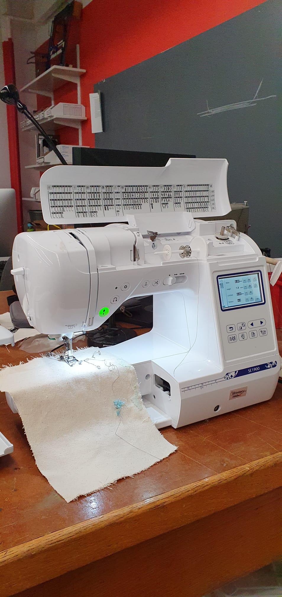
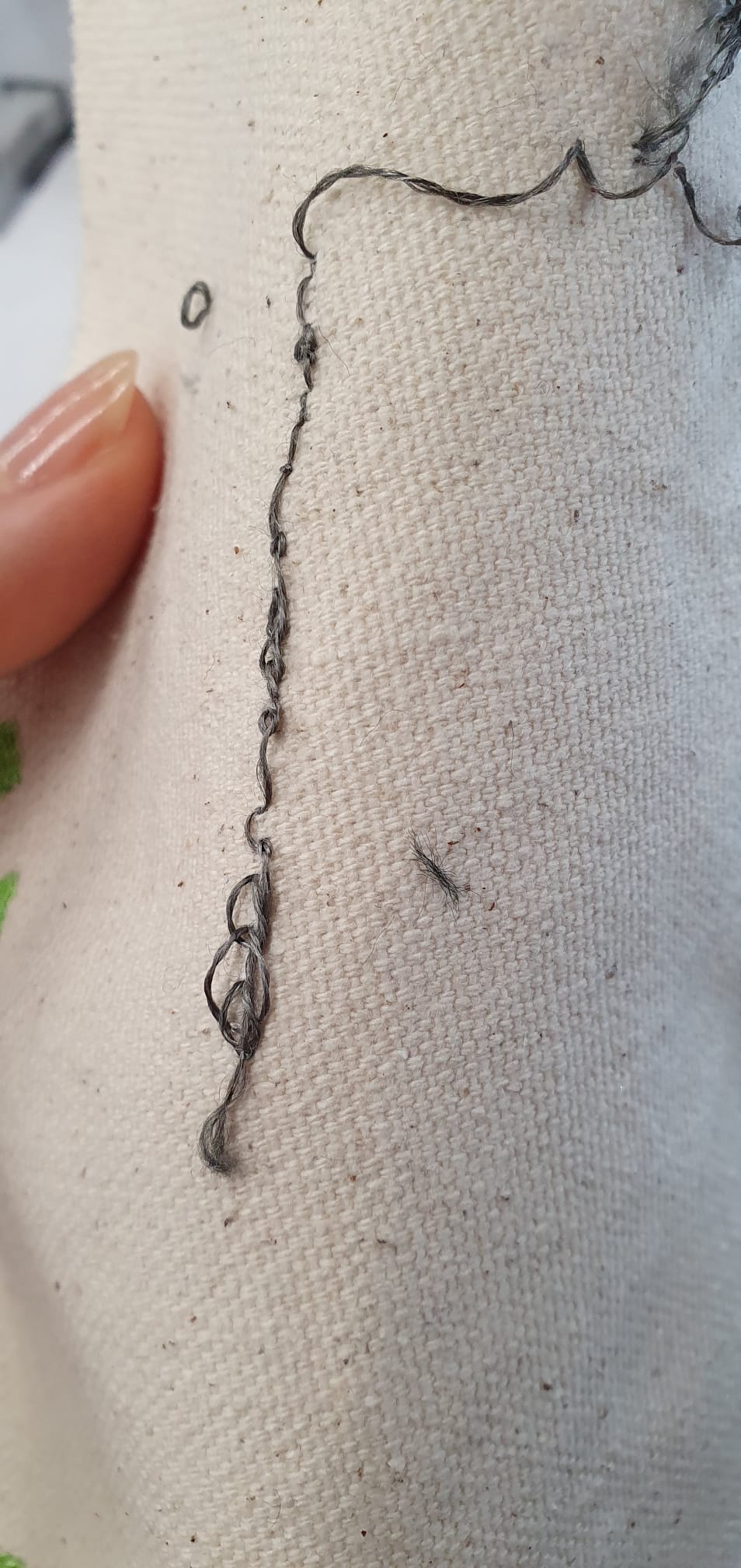
The thread kept on snapping, and I knew it had to do with tension. I tried a few different settings, but the thread also seemed to constantly get caught in the sewing machine. In addition,
conductive thread is often quite coarse and usually made out of stainless steel fiber, which can blunt your scissors. I suspect it can affect the internal mechanics of the sewing machine too.
Therefore, I would like to do some more research and experiment a bit more before I start making my own digitized electronic circuits. I am particularly interested in finding out how we can use different stitches to replace resistors, just like
in the Post, Orth, Russo and Gershenfeld (2000) article: "This level of stitch control and yarn variety brings up the possibility of replacing discrete components such as capacitors,
resistors, and inductors with specific combinations
of thread and stitch pattern." (p. 845).
For now, please enjoy a different kind of sewable circuit I made a while ago, with a LilyTwinkle (props to Leah Buechley) and sewable LEDs!