Week 5
Electronics Design
The Art of Electronics, Electronics Design Automation crash course, LEDs and SVG-PCB!
This week was fun! I spent most of my time deep diving into the basics of electronics and EDA, and had a lot of fun using Leo and Quentin's SVG-PCB program.
I went back to Jake Read's recitation during Electronics week, which was very useful in refreshing my memory. I also learned that SparkFun has some amazing articles on all the components you can think of, I will definitely be using their resources in the future.
Anthony Penness' document on electronics, pull-up and pulldown resistors was also good in clarifying some concepts in relevant ways, although I would have loved to connect a bare LED to a power source without a resistor and see it go up in flames (figuratively ofcourse). I think it would have been quite educational :)
SVG-PCB
For this week's assignment, I used SVG-PCB. I was blown away by it during Thursday's recitation, and loved the fact that it is code-based, has great documentation, and an interface that allows you to change the electronics in both the code and visual editor.
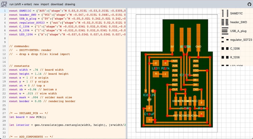
I used two already existing files on SVG-PCB. The hello.D11C.blink.js which includes the board we were recommended to use for this week, plus an LED:
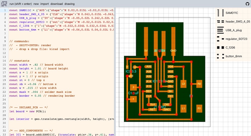
And the hello.button.D11C.js which has a button, minus an LED:
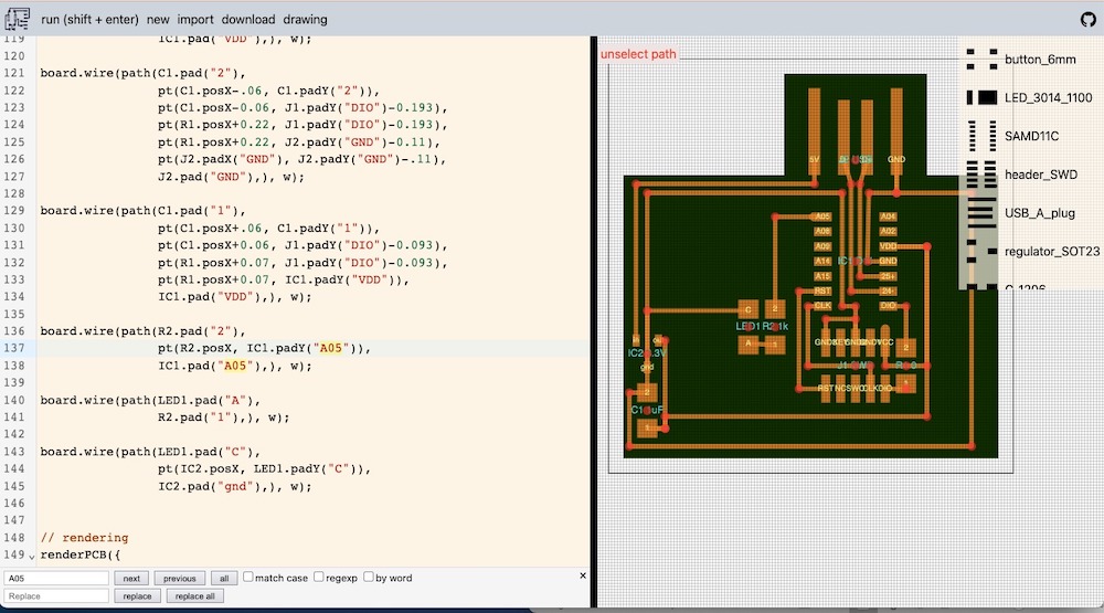
I took both and went with it. After checking with my peers, I learned that the LED should be positioned on a digital pin, so that I can program it later. The SAMD11 datasheet shows what each pin on the chip is:
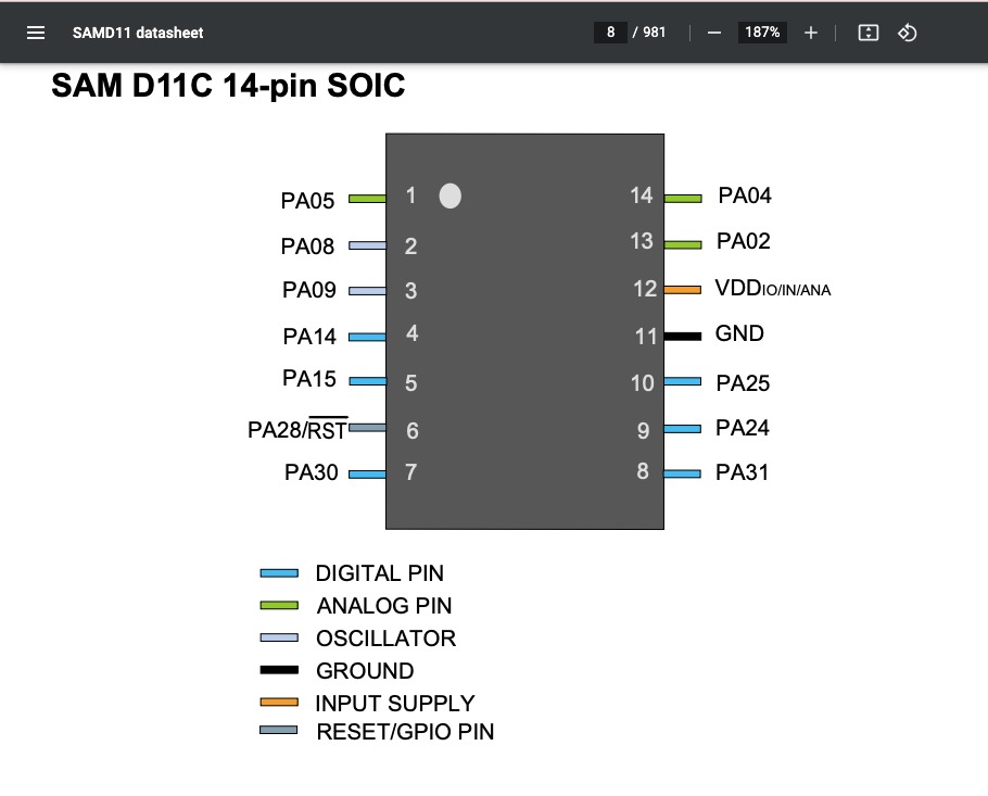
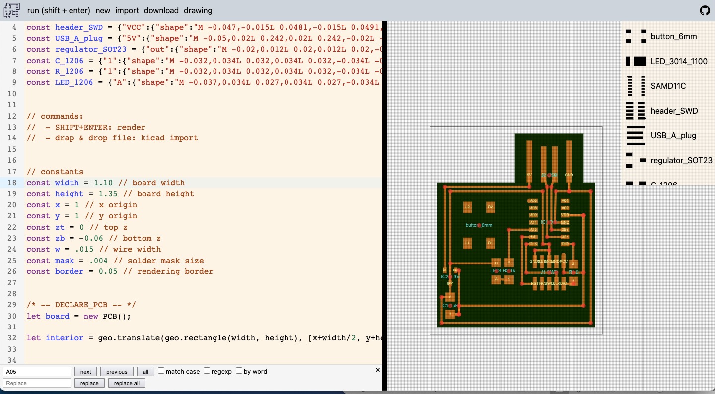
The LED+resistor were currently on an analog pin. Because of the positions of the other components, I decided that pin 14 and pin 15 would be the best places to position the button and LED+resistor, respectively. I changed the dimensions of the board (height and width) and moved some of the components around to get more space to add the button (which is huge compared to all the other components!).
I went about editing the position of resistor first, since it is connected to the LED. This was surprisingly easy! Changing the position of the resistor meant I automatically changed the position of the LED because of their interreliability in the script.
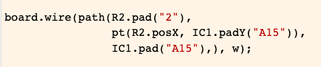
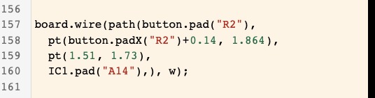
I then added the button onto the board in the visual editor:
With this line, I snapped R2 from the button, which means they are now connected. If I manually drag the button to another place on the board, they would still be connected, and the same if I moved the chip around.
Here is the finished ensemble:
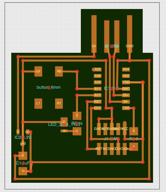
When I got around milling it however, the traces coming from the USB port to the chip weren't separated. I should have paid attention to the milling design rules assignment from Electronics Production week! (Refresher: the bit can't mill traces smaller than 0.016 inch, which is the same as the size of the bit!).
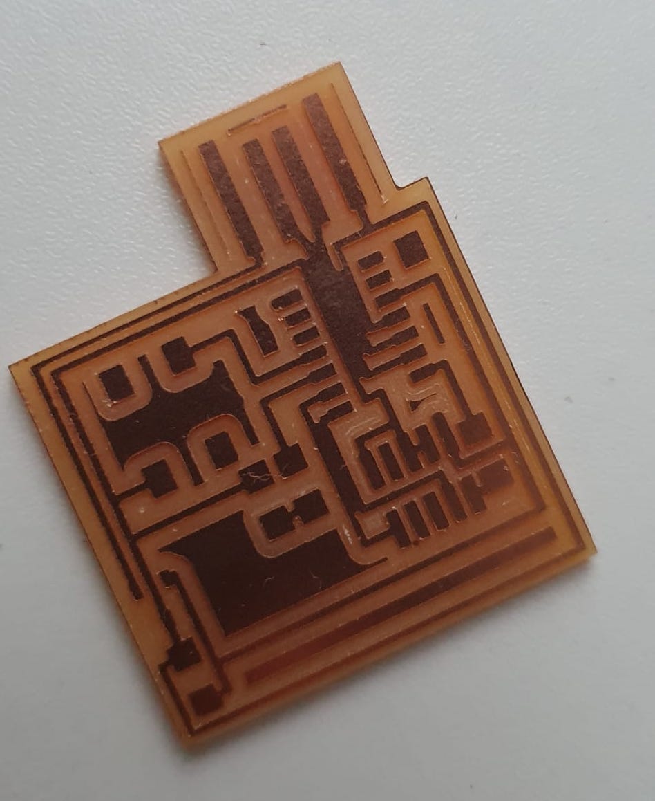
In my case, the traces were too close together. Back to the designing board! Luckily, Quentin helped me out with this, and we were able to change the width for those four lines only, instead of changing the overall width parameter in the script.
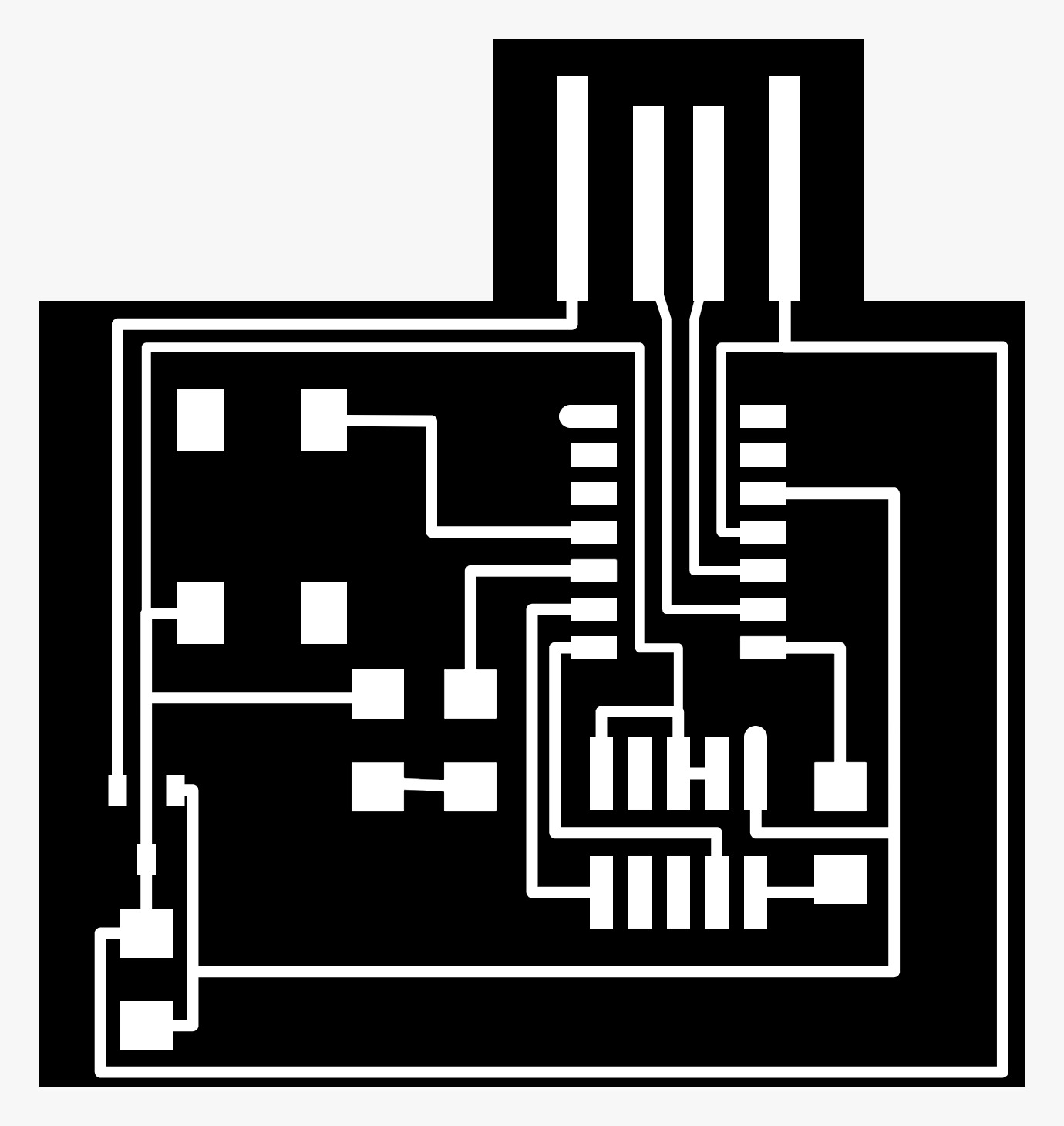
Here is the new file:
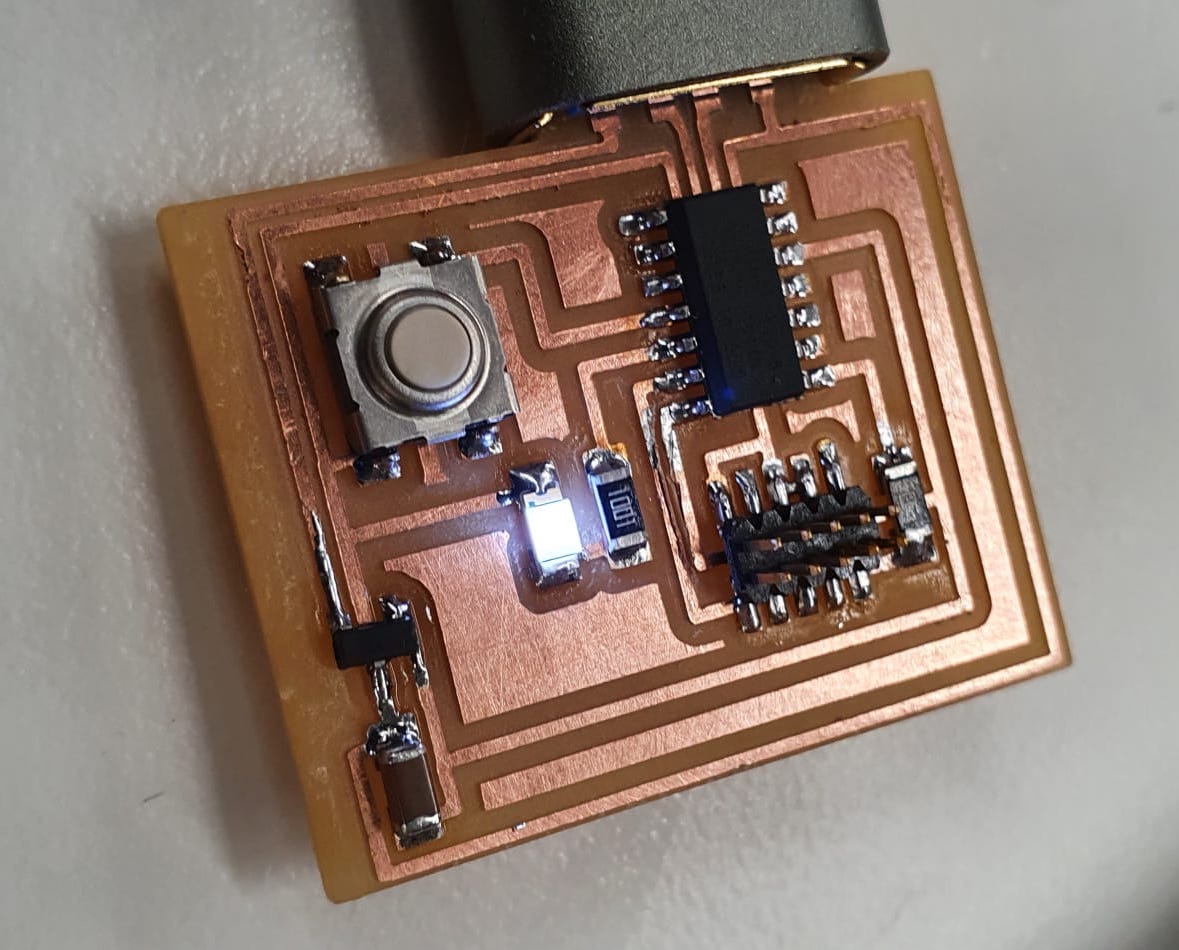
The soldering part was fun, and I could see I made some progress. I positioned the components in the way I wanted them, and started one by one.
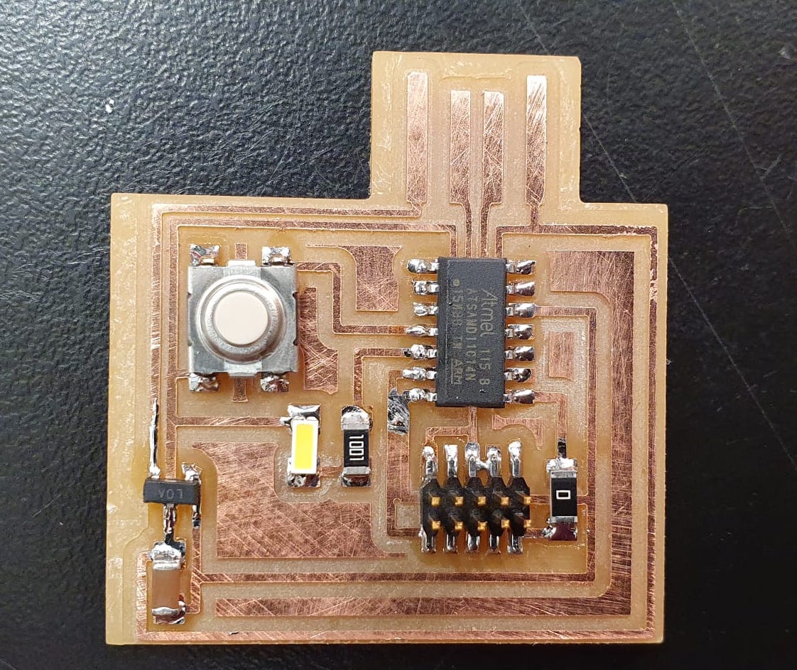
After I was finished, we found out that there was another trace (going from the chip to the 2x5 header) that was't separated either. But a ruler, knife and a steady hand can do wonders and it was quickly fixed! On to the programming!
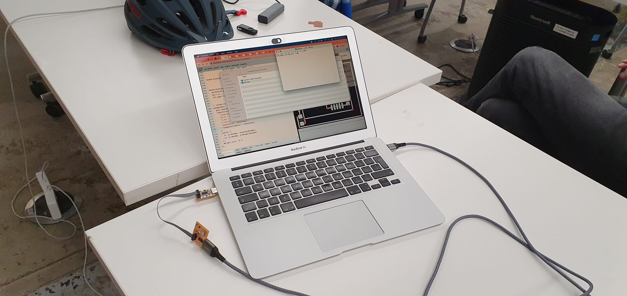
After openocd'ing the board using a programmer, it was time to download the FAB Sam Arduino library, that would allow Arduino to recognise our SAMD11 board and program it later.
Quentin showed me how to do that, and helped me the first blink program.
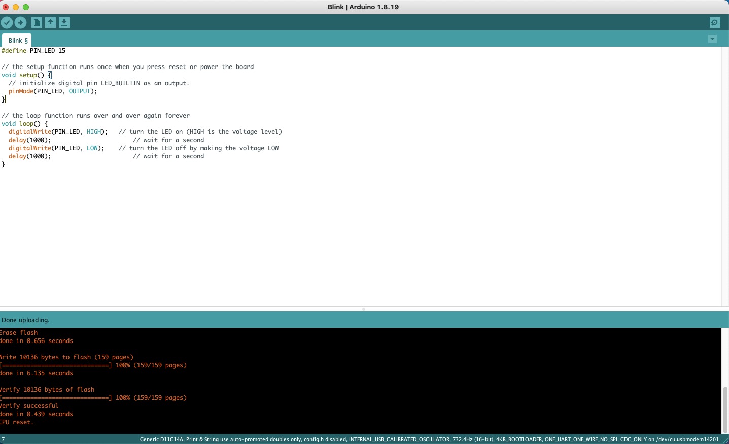
It works! The board is ~alive~
Group Assignment
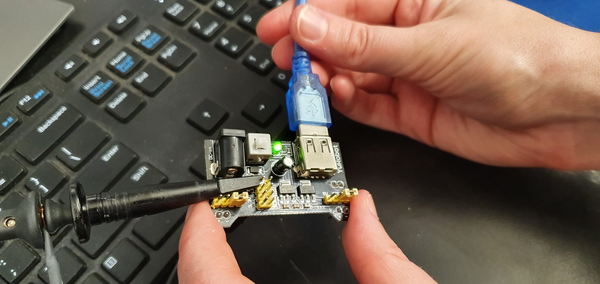
Using the oscilloscope was quite interesting. We found a board in the lab that we wired up to the oscilloscope and experimented a bit with the knobs and buttons. We wired up the ground and 5V power, and because the board had a button, we could see the current changing on the oscilloscope.
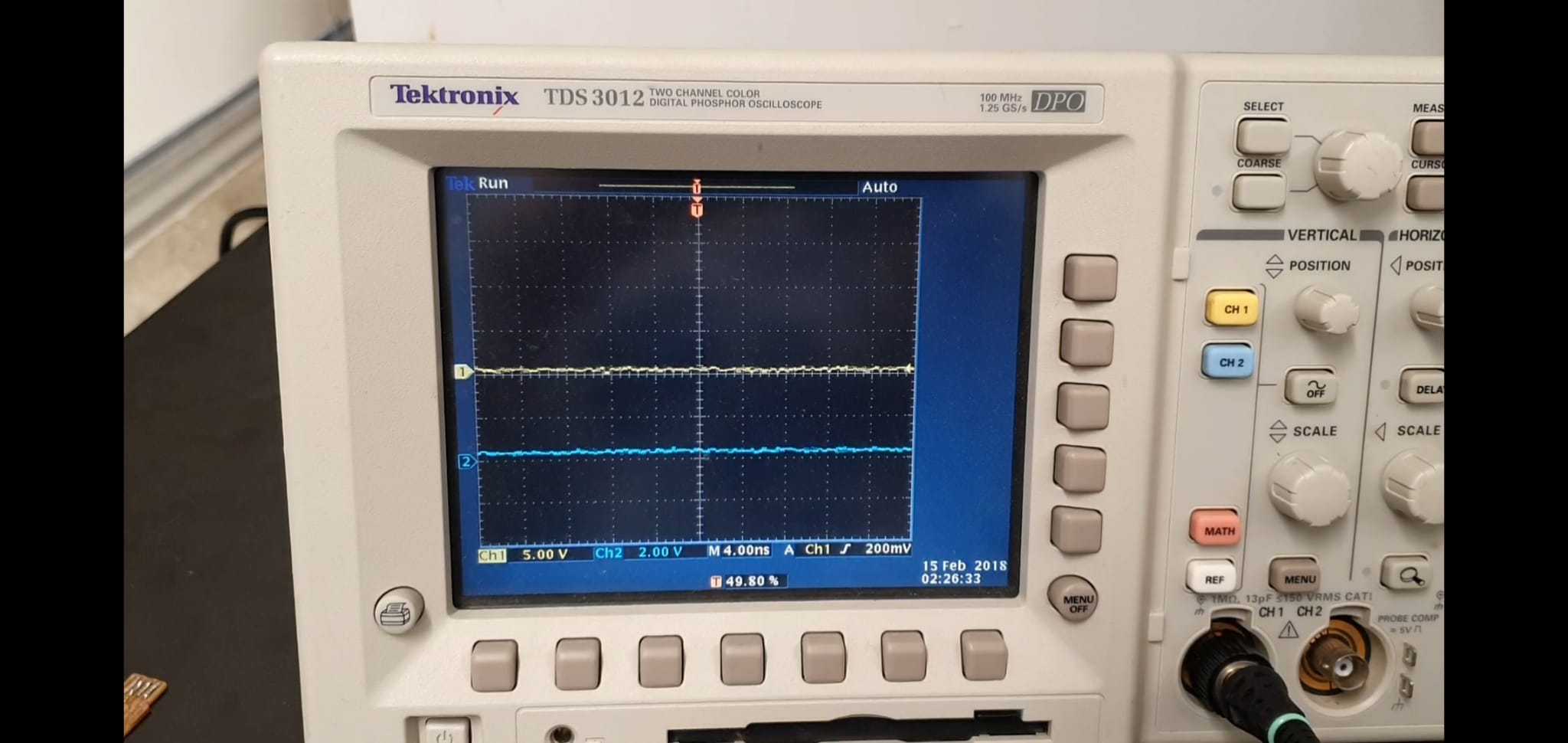
Here is the base line, centred using the horizontal and vertical position knobs:
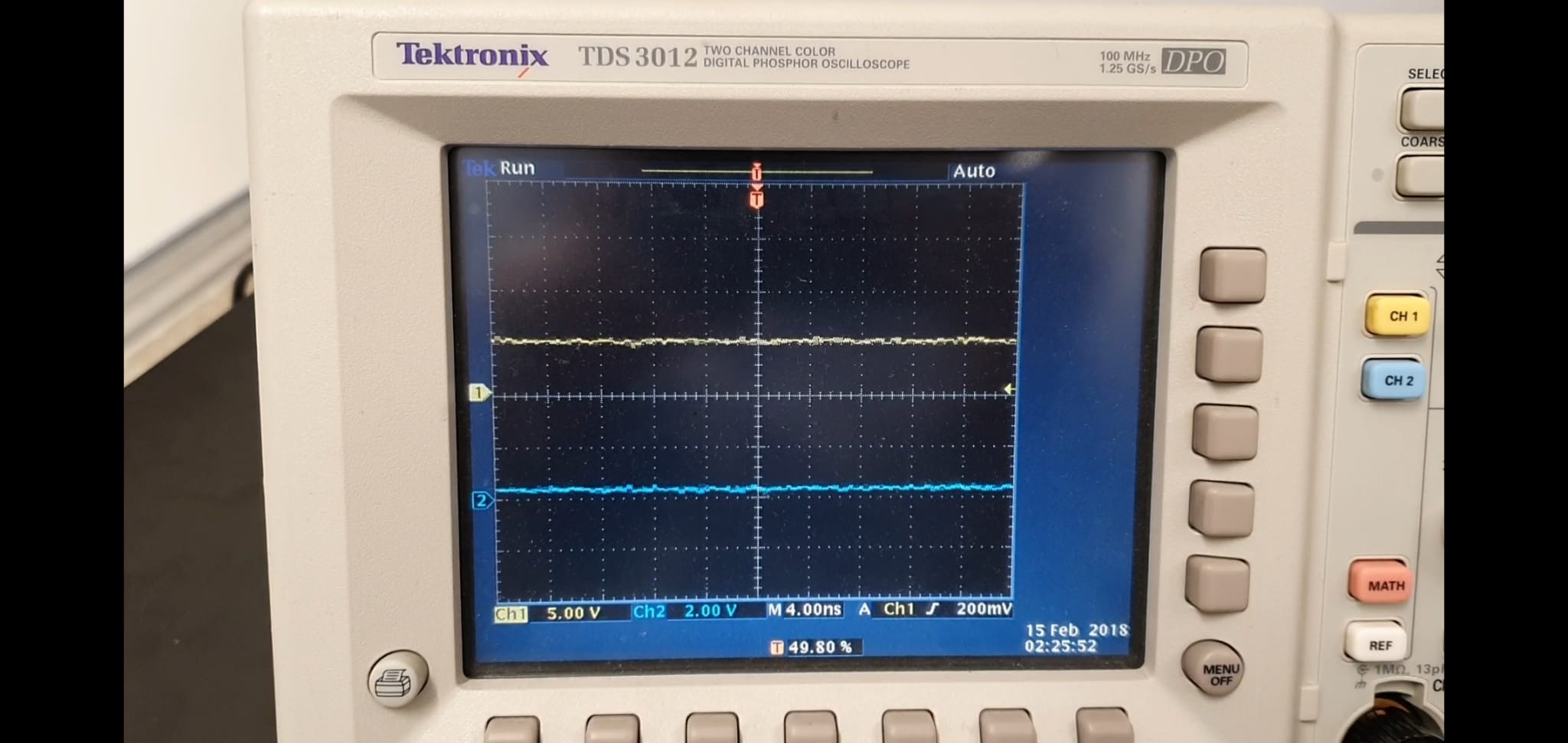
When we are about to press the button:
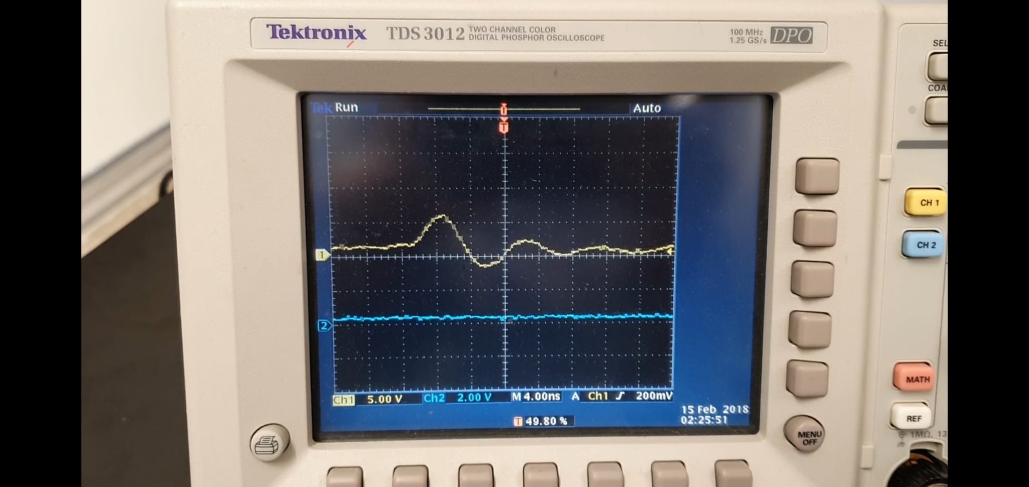
And here is the voltage jumping up!
We used several other boards that we found in the "Working Programmers" box, but I doubt they were working at all, because we couldn't get any signal.
There is definitely a lot more to learn about the oscilloscope and I would love to delve deeper into it.