Week 7
Embedded Programming
Arduino, SVG-PCB and blinking lights like there is no tomorrow

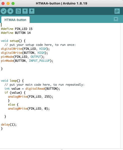
This week's assignment was to use the board I made two weeks earlier, and program it in fun and interesting ways. After some tinkering with Arduino, I got the button program to run on my board! I used Leo's tutortial (https://github.com/leomcelroy/fab-notes/blob/main/PROGRAMMING_SAMD_CHIPS_ARDUINO.md) which had all the steps I needed.
Here is the code:
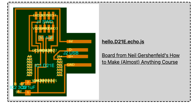
It was pretty simple, so I decided to make another board. The aim was to create a pcb with a RGB LED, a button, and a capacitive touch pad that you would use to control the colours on the RGB LED. So I jumped on SVG-PCB and found one of the SAMD21 templates:
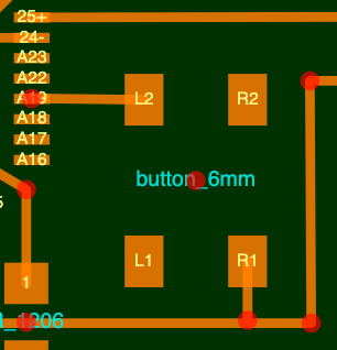
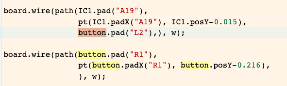
I repositioned some of the components to add the button, and in the code attached one leg to digital pin PA19 so that when I move the button around, it is still connected. Pretty simple to do:
Here is the code snippet:
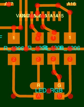
I then added a RGB LED and used the resistors for each leg (R, G and B) as a bridge to go over the GND path, and connect to three separate digital pins. Bonus points for multifunctionality! The RGB is a common anode (+) LED, which means that the fourth leg, labelled 'A' in the editor, will connect to the power stream (VDD/VCC).
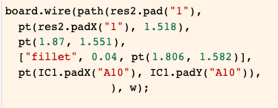
You can see I experimented a bit with fillets as well, which made the paths much smoother. I will definitely be using these more! Here is a code snippet that shows how to use it:
Finally, I added a path for the touch pad to analog pin PA07, through a 0ohm resistor bridge. I added the actual pad in InkScape (Leo if you're reading this, sorry to disappoint you).
The final look:
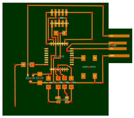
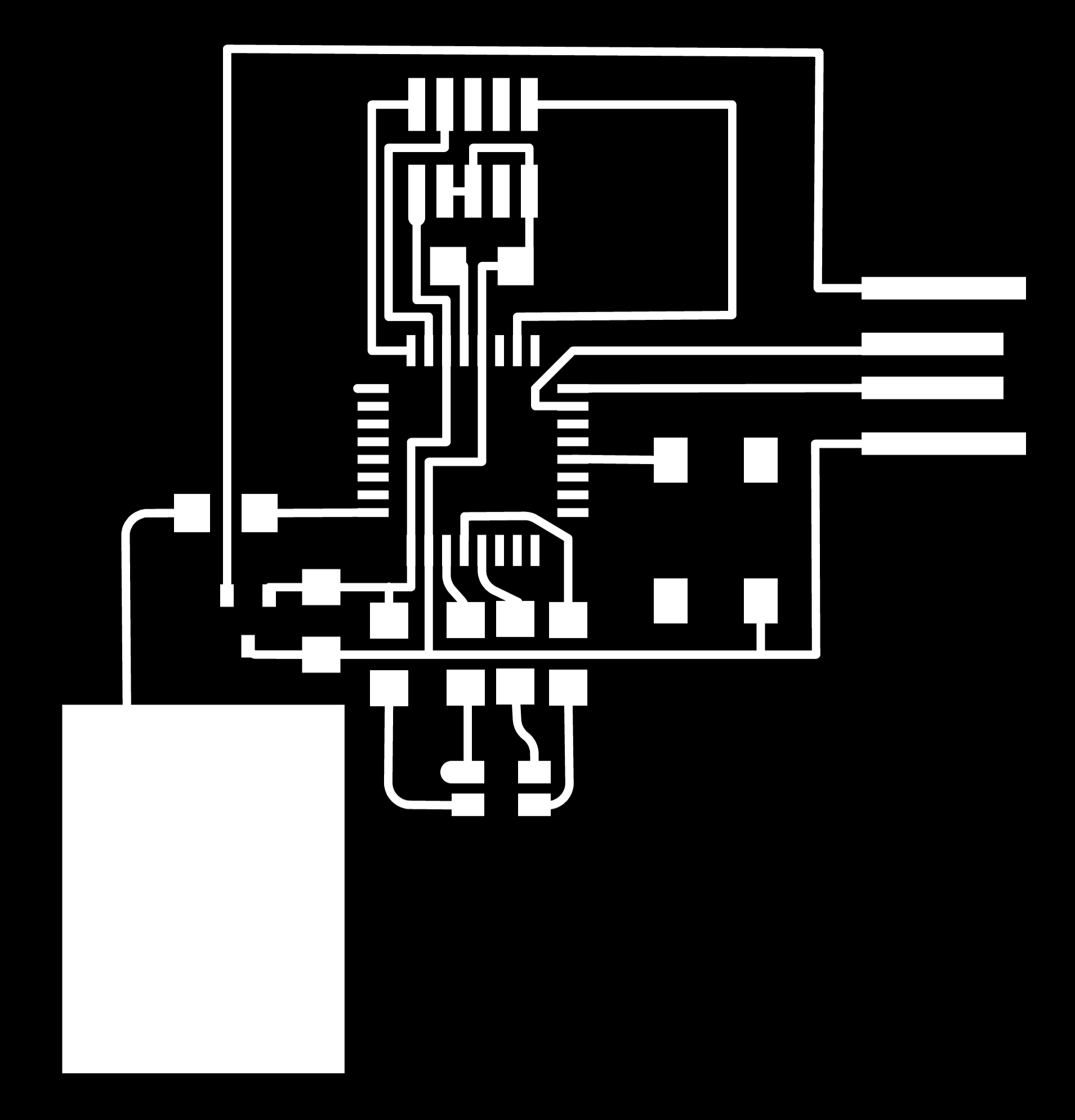
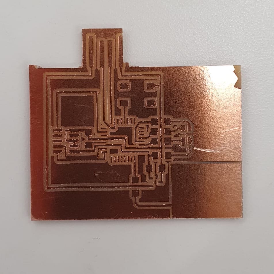
And changing the LayerColors in the editor I got a nice png for the traces:
On to the milling!

There was something wrong with my outline png (which I got from InkScape) because mods didn't recognise the upper cut on the board. When I ran it again with a better png, it seemed that everything got offset by a tiny bit, so I ended up with a tiny USB port, with some of the GND path eaten up. Alas, there is no time to fret,
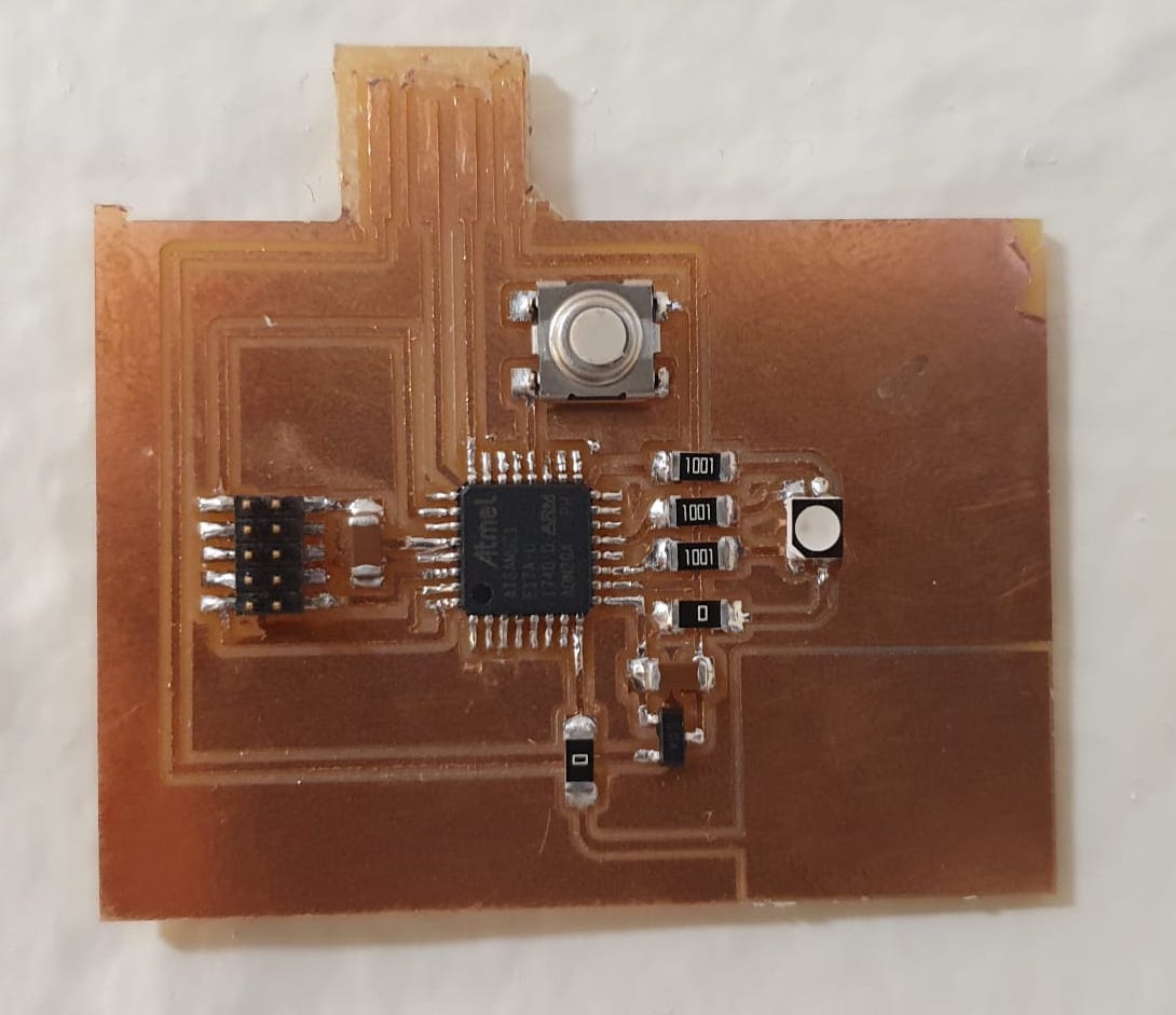
and with some gentle sanding and a bit of soap, here is how the board came out:
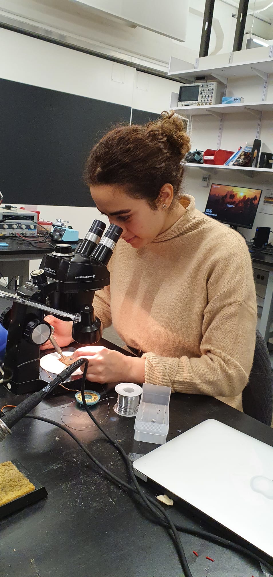
When it came to the soldering, I had practically memorized all the components and where they should go, but kept my SVG-PCB file close.
I accidentally shorted two legs on the 2x5 header, and might have put the heatgun too close to remove it:
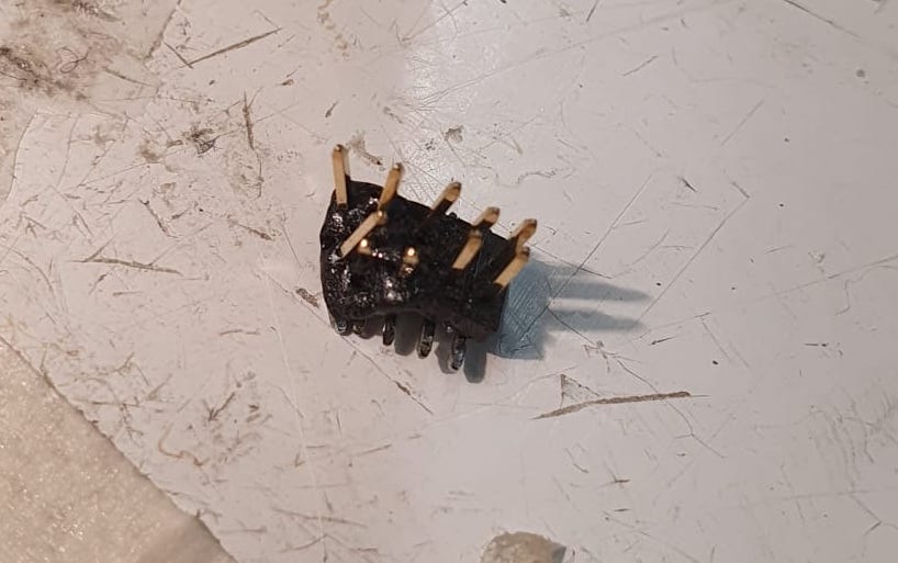
In all honesty, this wasn't my best soldering at all. In fact, I am so unhappy with it that I am determined no one will ever see it. It will be buried into the depths of the earth after I salvage the components. To make matters worse, the exacto knife didn't cooperate either. But I got to document it to prove its existence so here it is:
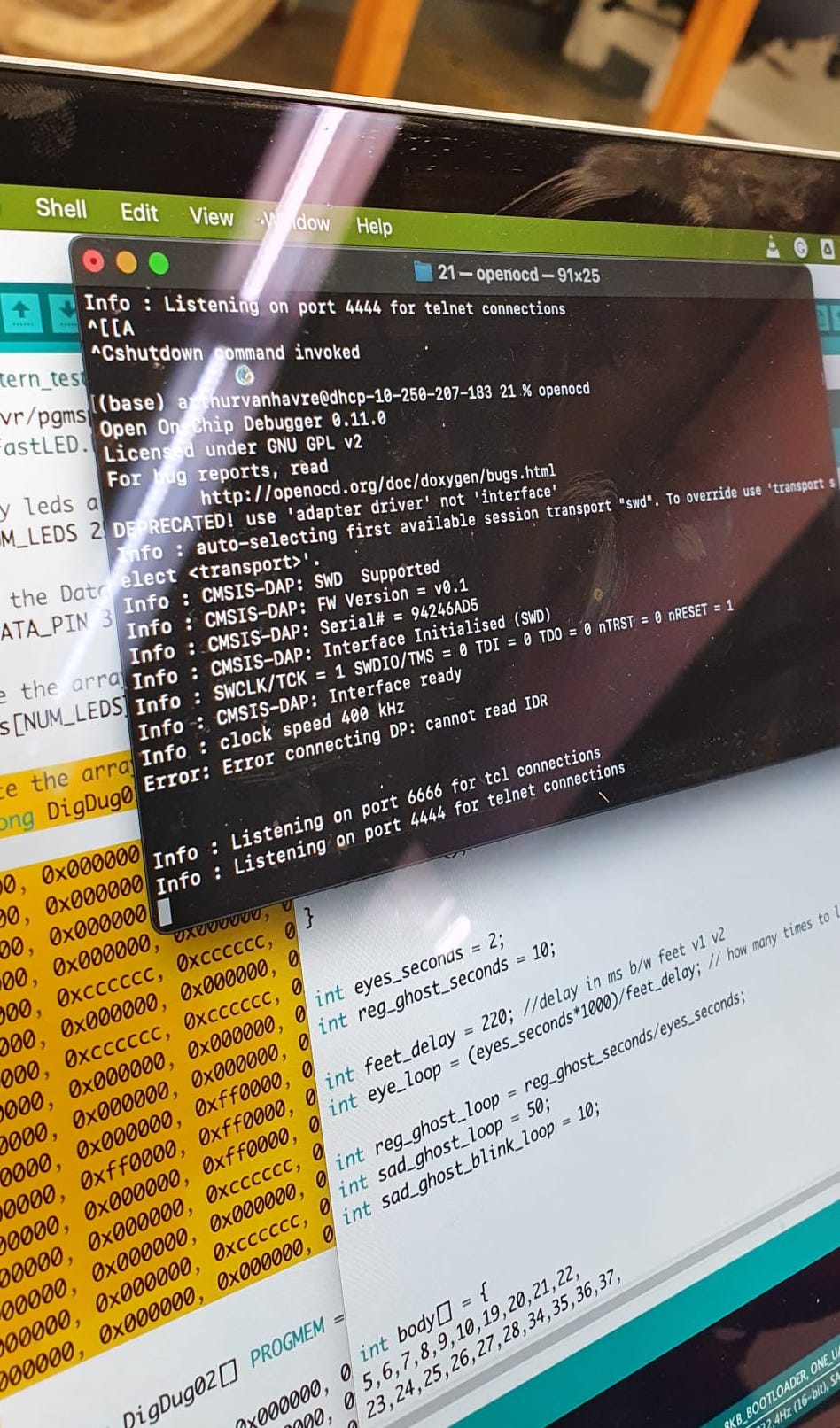
Unfortunately, I kept getting an error when I tried to openocd the board:
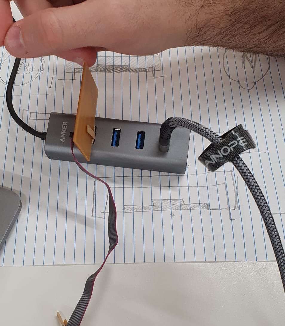
At this point, I believe there could be about a thousand things wrong with the board, because even the toothpick didn't help:
Using the multimeter, I checked for continuity on the pins, and the RGB lit up! That's got to be good :)