Week 9
Input Devices
RGB LEDs, Arduino and the philosophy of spirals
Fixing ancient board
This week started off with my inner Neil (read Quentin) telling me to fix my board from Embedded Programming week, and get that to work before I design any new boards. Fair enough: this is the first time I am using a D21, and it spirit of working in spirals, I should probably get this old board to work before I go on any more pcb adventures.Sadly, I lost the svg-pcb file of my original design, but luckily I still had my png images:
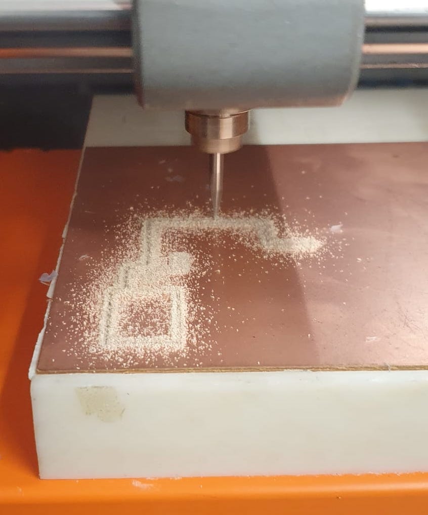
We didn't have any 1/64" bits in the lab, but I found another strange looking kind. It looked like this:
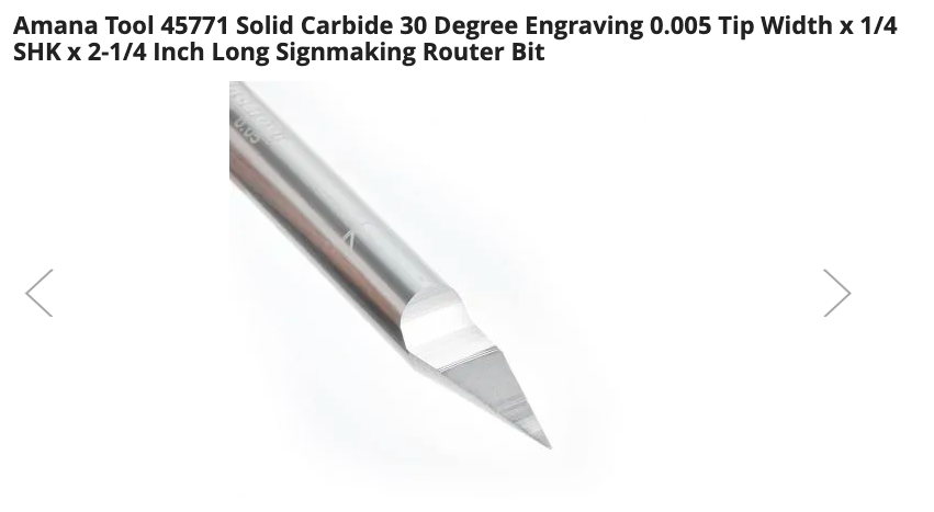
I was told that this is just a different version of a 1/64" bit so I went with it. I fed my files into mods and started milling.
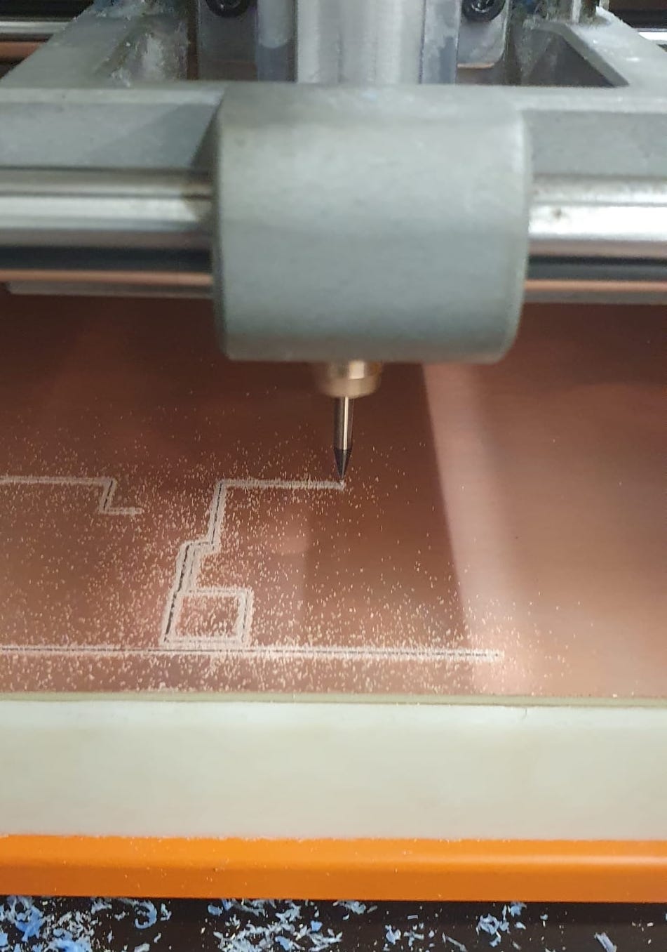
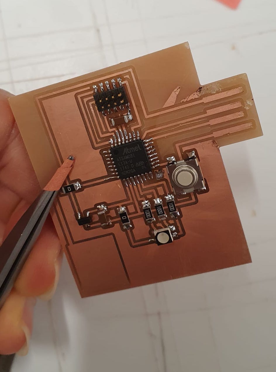
The board came out funny in a number of ways:
- It was really really hairy, and even after I sanded it gently it looked pretty messy. I used a gas duster to get some of the finer strings of copper out of the way.
- The USB port came out narrower than it was supposed to, so I figured it had to do with the way I exported the png from InkScape and the layers I selected.
- The traces were super thin.
- The traces were milled way too deep.
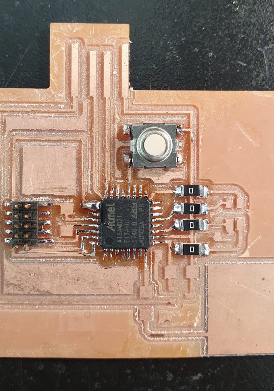
A few of the unused D21 pads came off, and I think it is because of the traces being really thin. In addition, one of the pads of an important pin on the D21 came off mid-soldering as well, so I soldered it together with it neighbouring pin that wasn't used. I know, very risky.
All in all, it came out pretty good, minus the bodged USB port.
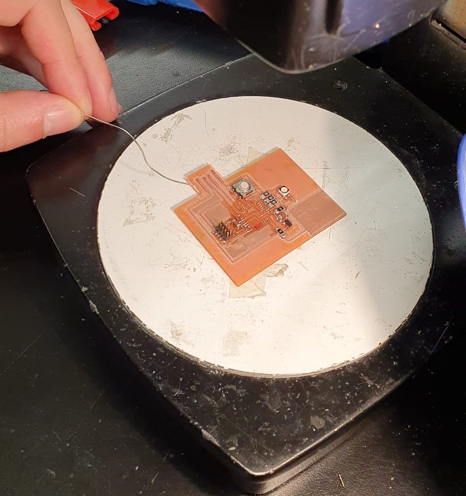
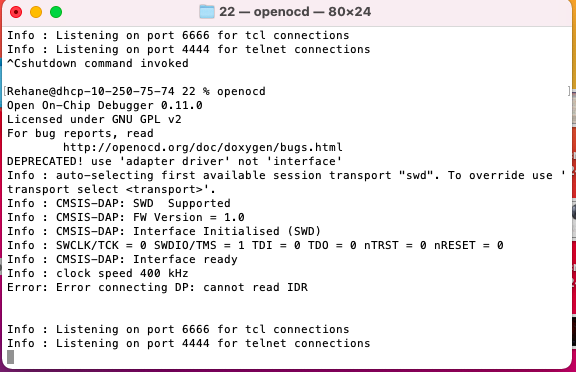
Once everything was there, I opened OpenOCD and with full confidence ran OpenOCD on the board with another programmer on a jolly Friday afternoon. Guess what? I didn't run. I used the D21E17A specific file (link here) and had it in the same file I had the openocd.cfg file. I oriented the cable connecting my board to the programmer in different ways, but still no luck. This is the error I kept on getting:
We even had a certain trespasser visiting the lab, who looked at it very intently, used the oscilloscope to confirm the board was indeed alive, but even with his help we couldn't program it! When Leo looked at it the day after, he found I had accidentally cut two of my traces coming out of the 2x5 header, so I performed the most precise surgery on it using a single wire from a stranded braid. It was so good I can seriously consider a gig as a surgeon post HTMAA. But no time for distractions, because even with all this intense looking at my board, fixing it and almost throwing it out of the window, it still wouldn't OpenOCD. At this point, let's just make another one!
Capacitve Touchpad V3
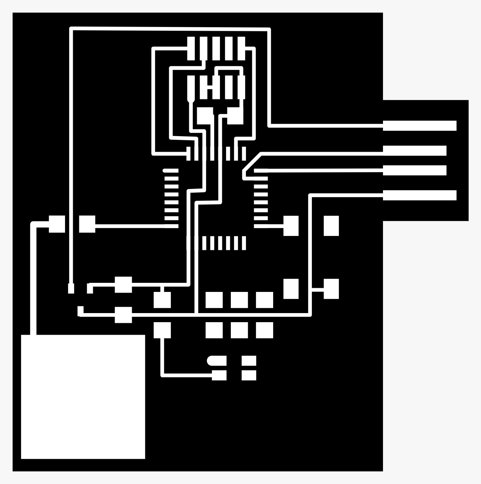
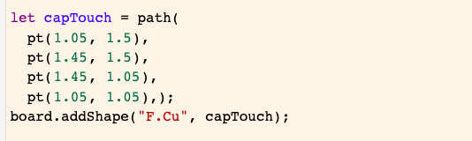
This time, I redesigned it in svg-pcb so that the USB port would come out neater. Plus, it is good practice and with svg-pcb it was a piece of cake. Leo neatly showed me how to add the touchpad in the editor itself, and it was so simple I can't believe I tried doing this in InkScape. Here is the snippet you would need:
This is how my final design looked like:
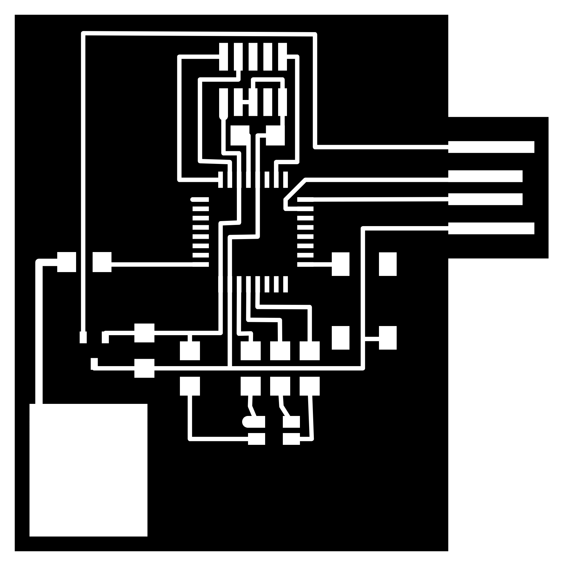
I had finished the design in svg-pcb in no time, ready to be milled.
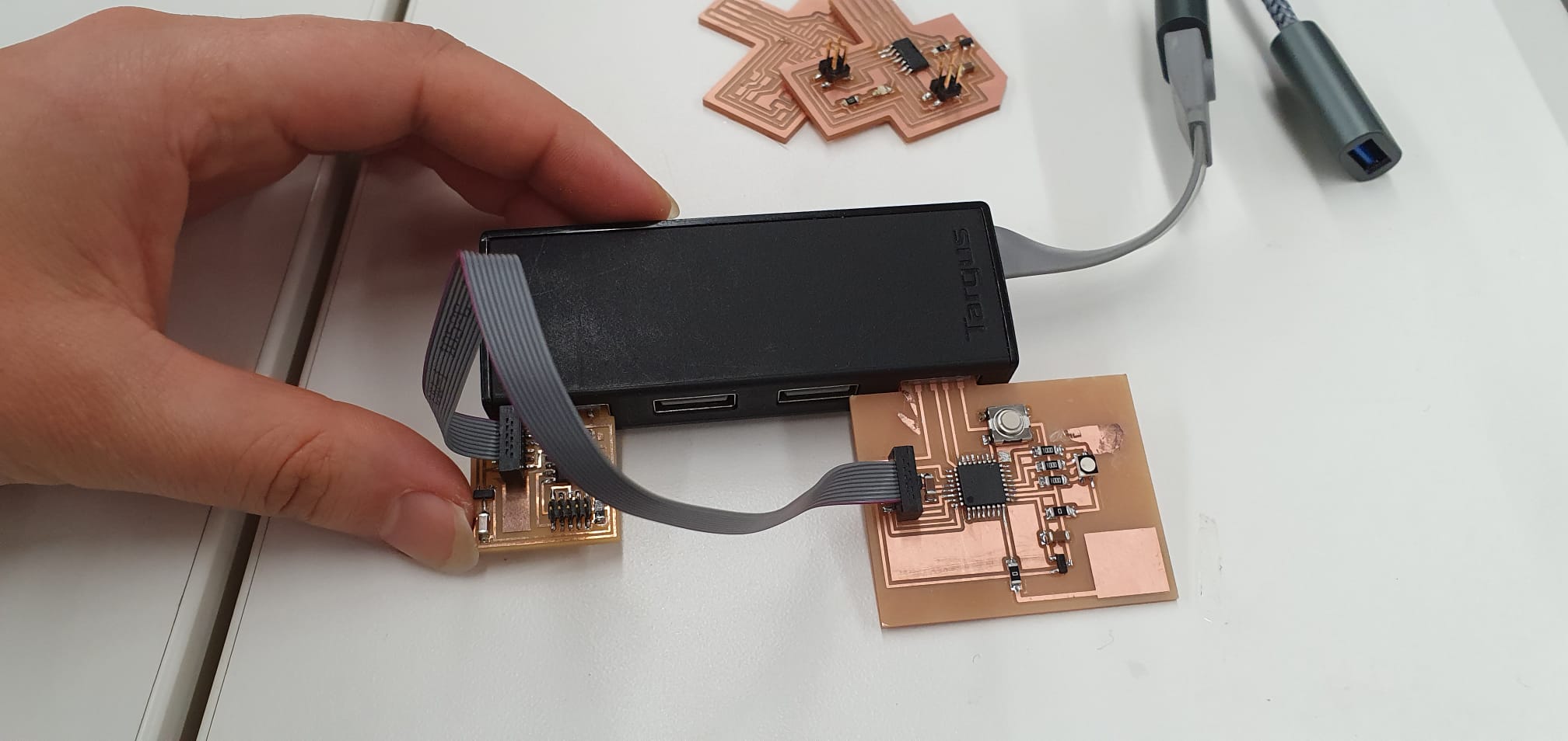
I soldered everything together and it came out pretty good again, but I tried to have no high hopes because looks can be very deceiving. Tyler showed me a neat way to get the excess copper off the board, which involves an exacto knife and tweezers, and I managed to get off most of it!
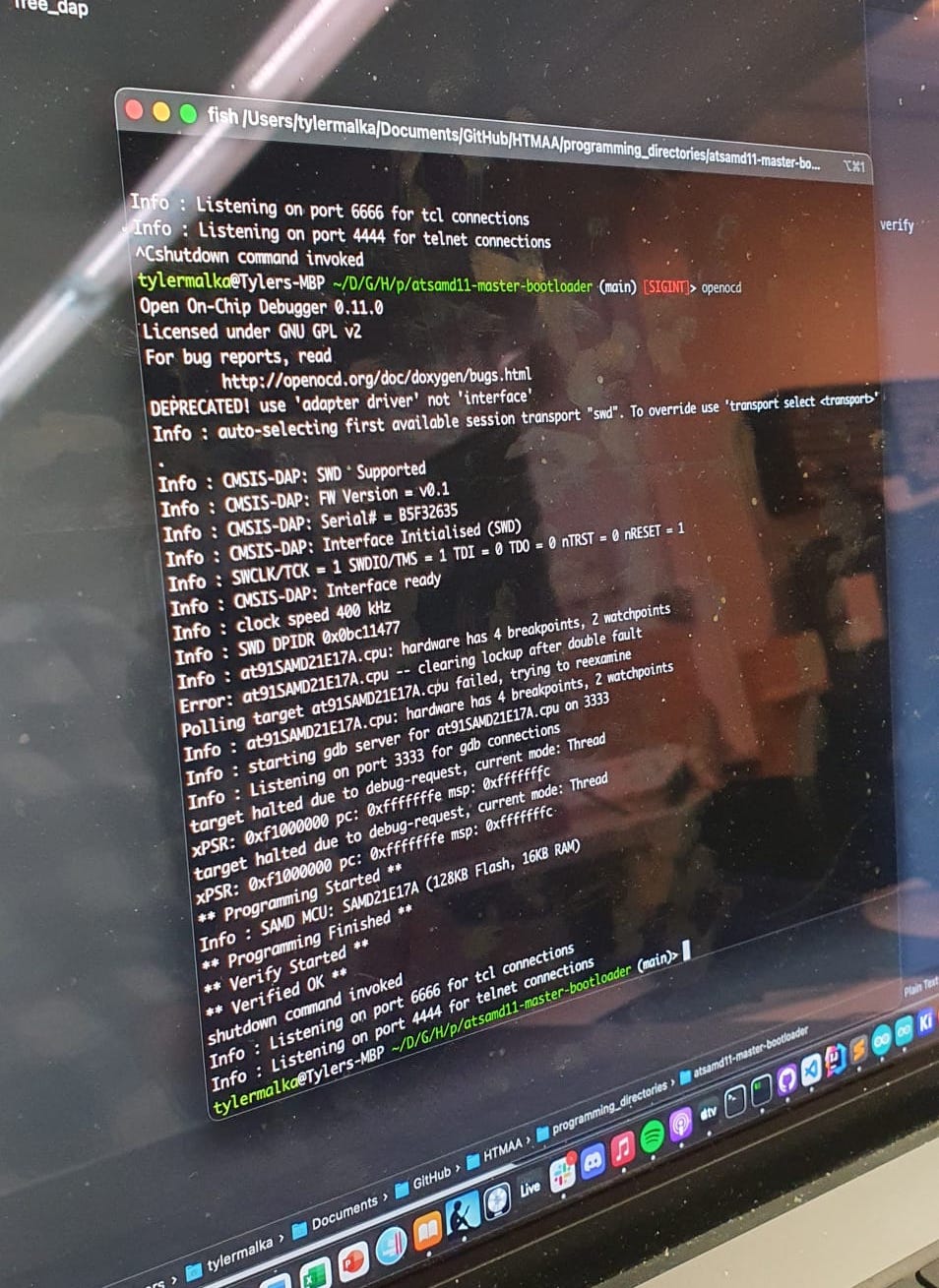
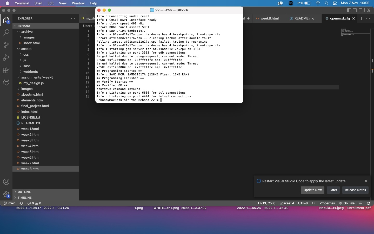
I openOCD'ed it again:
Success!
But the relieved feeling quickly turned sour again: the board doesn't show up as a serial port in Arduino or my Terminal:
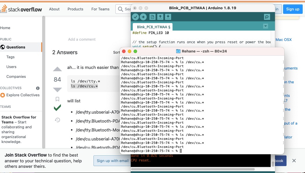
Very strange. After trying everything I could, including almost throwing it out of the window which seems to be my go-to strategy from now on, I realised I really couldn't figure it out. I was hoping for a miracle at this point. At office hours at MIT, this miracle turned out to be Quentin.
Apparently, the bootloader protection turned on after I openOCD'ed the board earlier. This happens to 1 in every 100 board so I count myself as one very lucky human being indeed. Quentin fixed it by running EDBG on it with a specific command:
-eb -t samd21 -F w, 2:0, 7
-F = refers to the fuses on the board w = write to 2:0 = from bith 2 to bit 0 7 = write the value 7 to it.
7 in binary is 111 so in this short command, we told EDBG to set the last 3 bits to 1, which turned off the bootloader protection, or more specifically the BOOTPROT (check out page 31/1111 from the SAMD21 datasheet). That solved it!
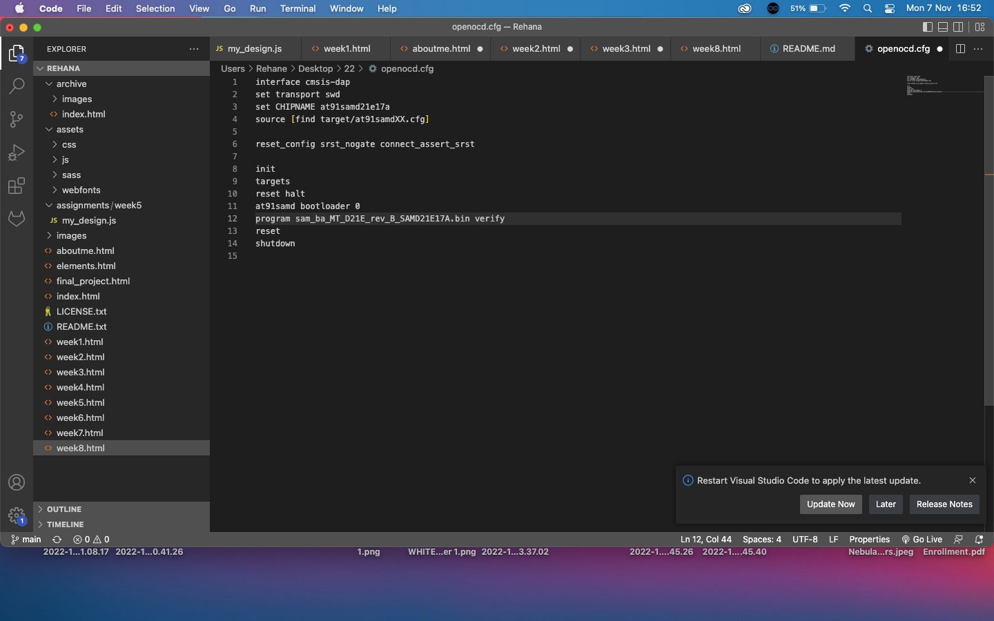
You can also solve it in openOCD by adding:
reset_config srst_nogate connect_assert_srst
after the source line:
Arduino
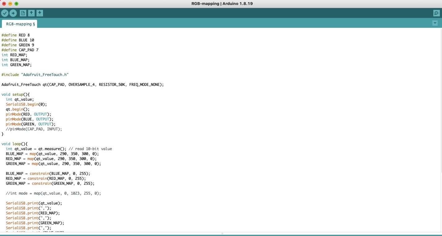
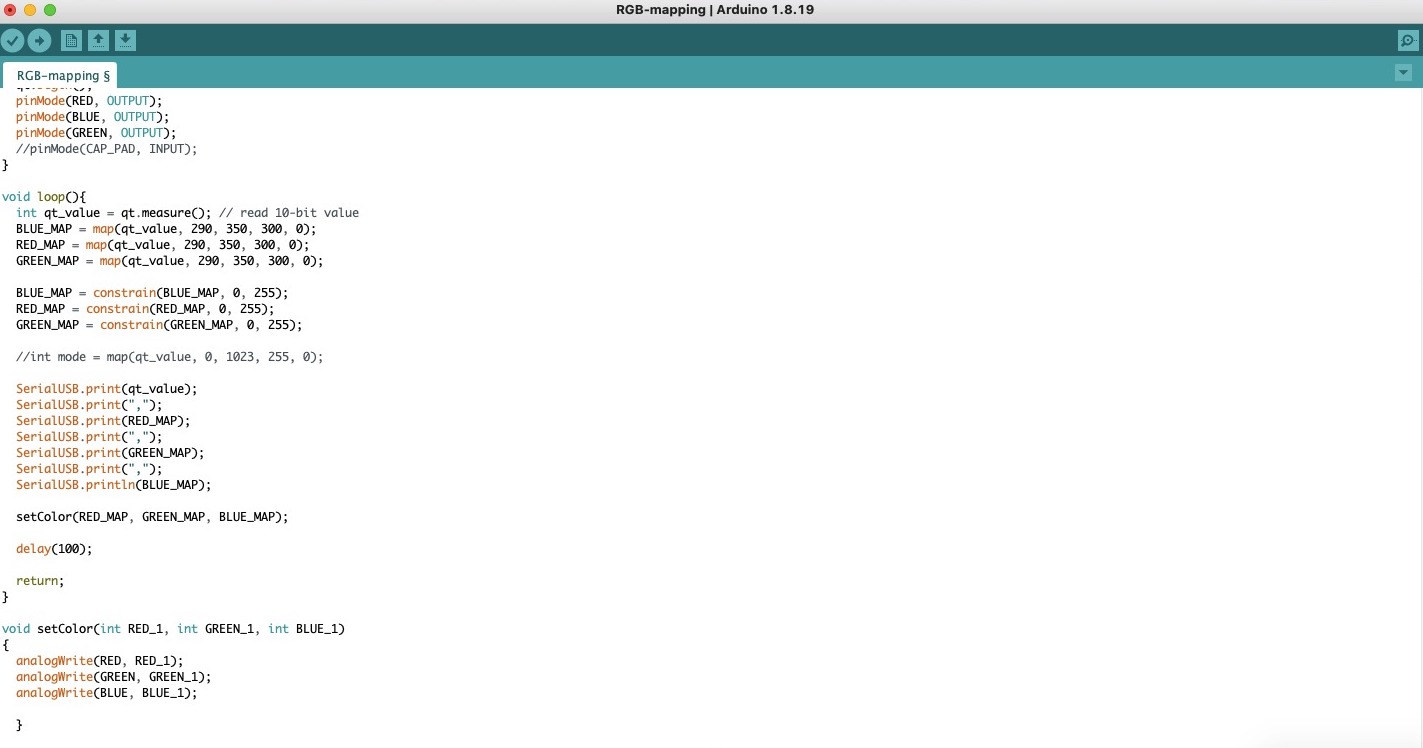
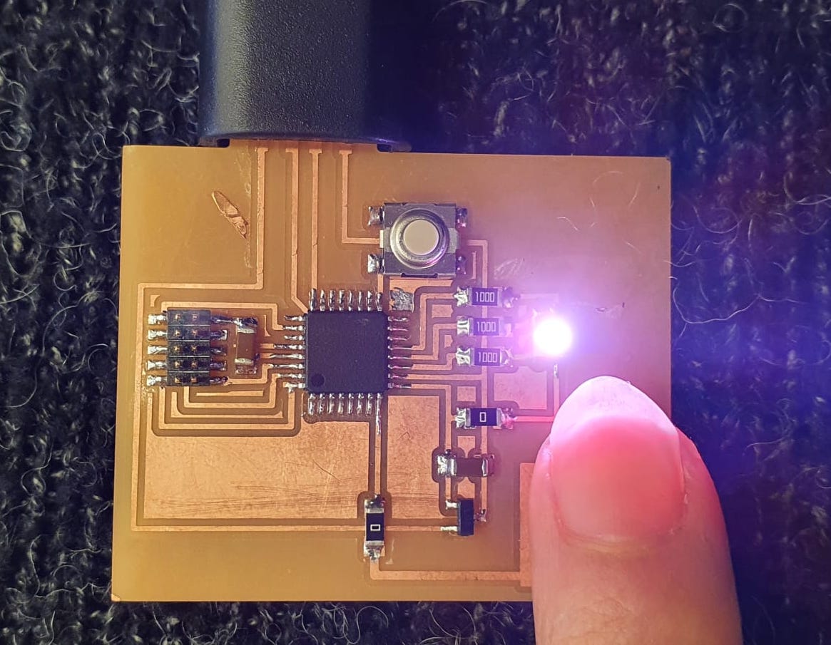
Now that was out of the way, it was time to actually program my board in Arduino. I wanted to use the capacitive touchpad to change the colours of the RGB LED, and used Quentin's FabTouch library (found here) and a tutorial I found online on RGB colour mapping (link here).I played around with the mapping values and got it to work!
Here is my final code: