Input Devices
Setting Up ESP32-CAM
Because my final project is about a clock that can "see" the users, therefore, afford interesting interactions. So this week, I tackled the input part of it. I planned to have the clock be able to connect to the other clocks wirelessly. After talking to Claire and browsing Cathy's website, I decided to use ESP32-CAM, which has both the camera & wireless connection capability that I could leverage.
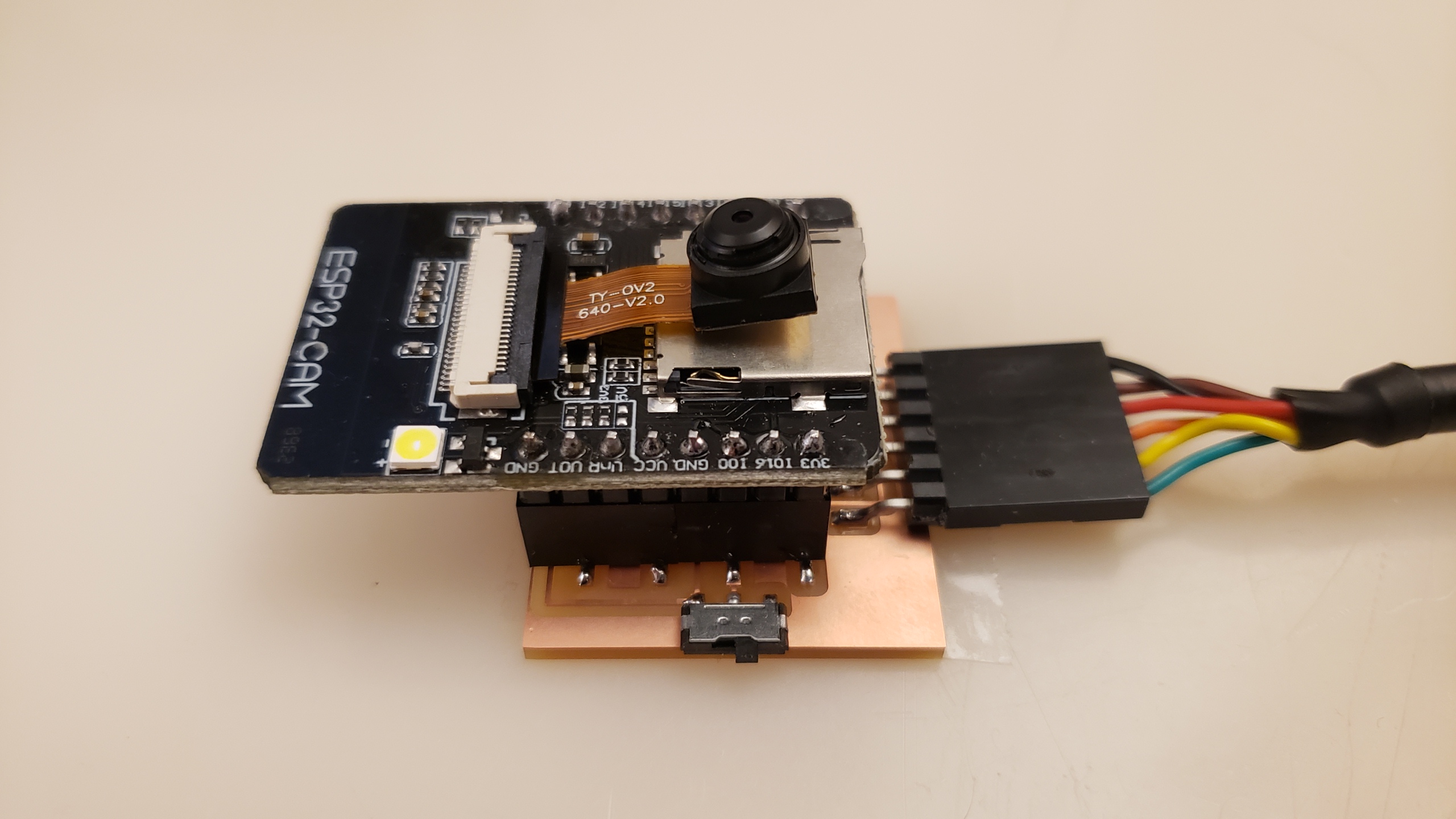
Nathan gave me an ESP32-CAM with FTDI (the device that was used to program it, the red one in the picture)
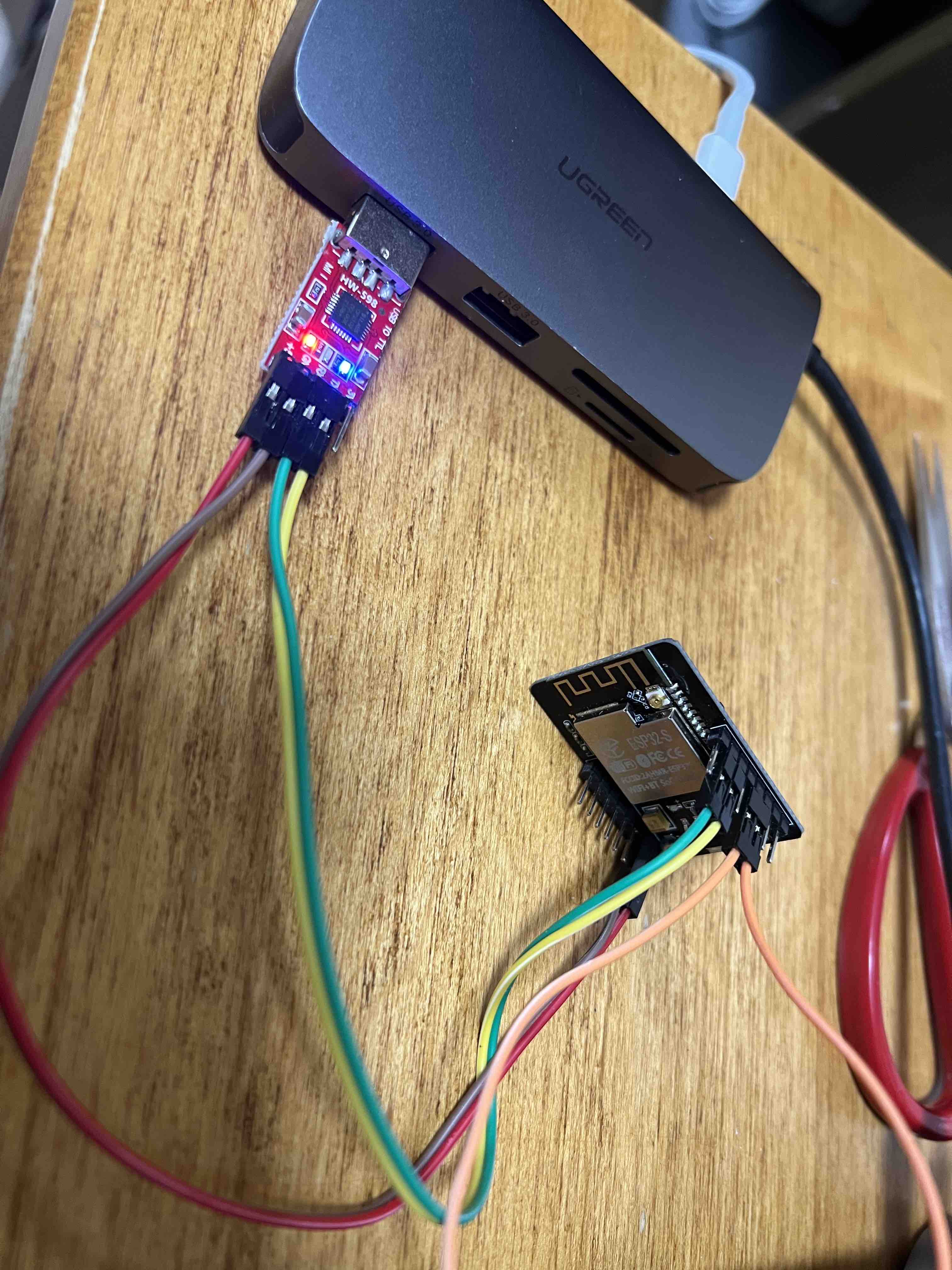
I first followed this video (this one
is
super detailed and useful) and this tutorial to test if I could successfully get the video stream.
But
soon, I
realized that it's hard to use Harvard wifi to send the data, and it didn't work with
phone's
hotspot it seems. Therefore I followed this tutorial to
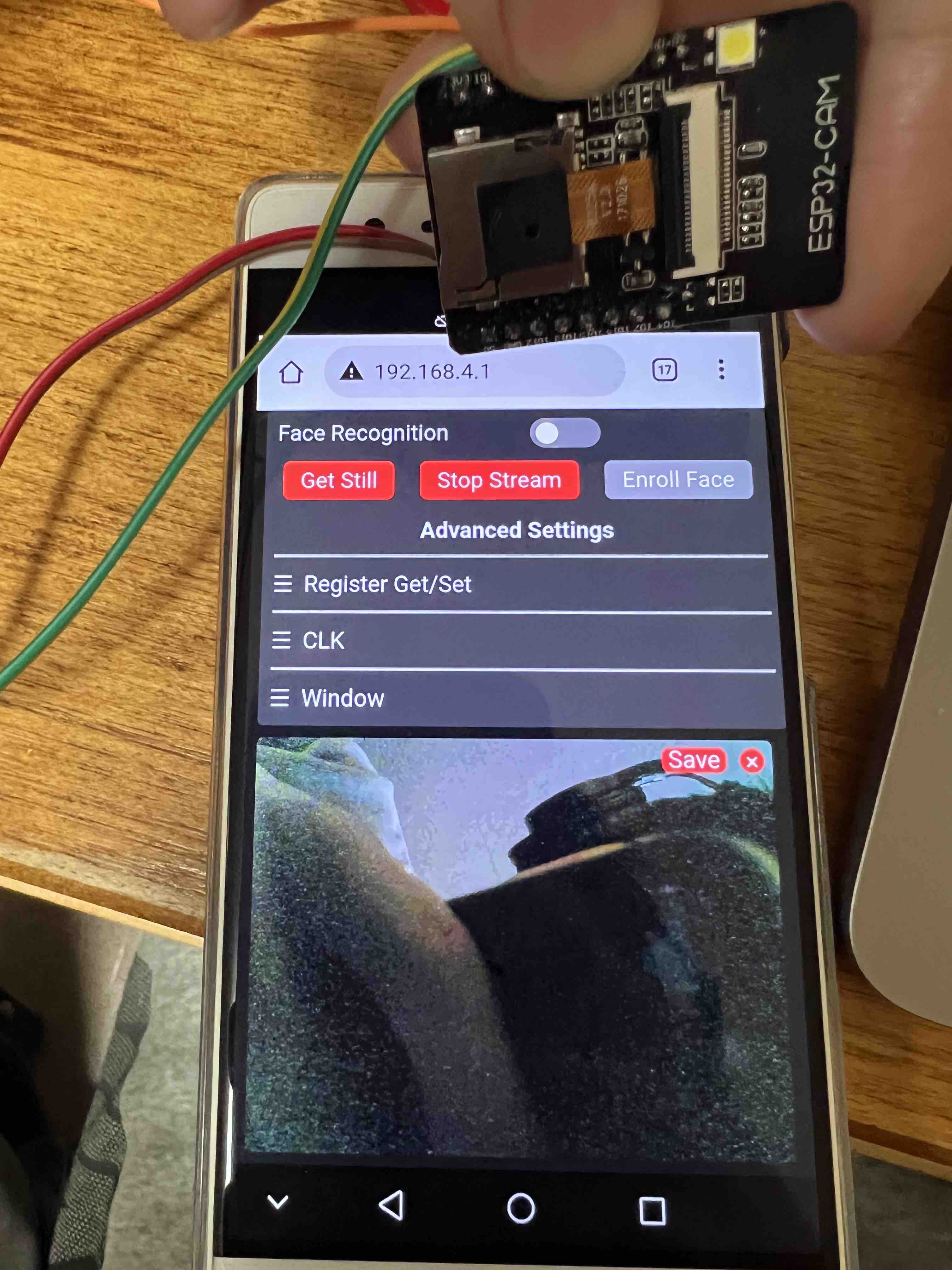
set my ESP32-CAM as a hotspot. Therefore, I could connect to it directly. And yeah, I was
able to
see the image after connecting to it and opening the http://192.168.4.1/!
Testing ESP32-CAM's Pins
Because I will be using the 28BYJ-48 Stepper Motor for the clock, and I plan to have two motors to control two hands independently, I need 8 pins in total. After some testing, I noticed only pin 12,13,14,15 was realizable to use. The 0,2,4,16,1,3 are not.
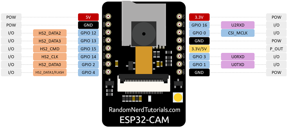
After inspecting the pinout sheet, I noticed that pin 0 is used for flashing mode, and pin 4 is for the flashlight (that's why the flashlight flashes according to the frequency if I do use that pin). Pin 16 should be working (and it did, sometimes), and pin 1 and 3 are for RX TX (serial connections). Theoretically, they should all work, but here are the combinations I tried and the results. Here the "lights" means the LEDs on the driver board of the stepper motor. The voltage is measured at the input to the driver board:
- 0,2,4,16: all four lights on, 4V, shaking but not rotating
- 0,2,12,16: all four lights on, 4.1V, shaking but not rotating
- 12,13,15,16, all four lights on, 4.1V, working
- 4, 13, 15, 16, all four lights on, 4.3v, not working
- 2,13,15,16, shaking not rotating
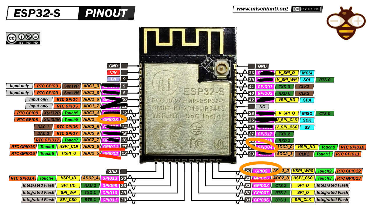
It's already 2AM in SC, but I don't want to give up, I pulled up the sheet for the ESP32-S (the chip that ESP32-CAM used) and marked out all the pins that the camera used. I noticed there are 3 pins that I can use (marked in orange, 2, 4, 33, they seem to have the closest capabilities compared to 12,13,14,15). That means even if I followed this tutorial to take out the flashlight and expose 33, I'm still one pin short.
At this point, I was very exhausted because I had spent almost two days testing this. I turned to Lingdong and Quentin. They both suggested I use another board to extend the pins.
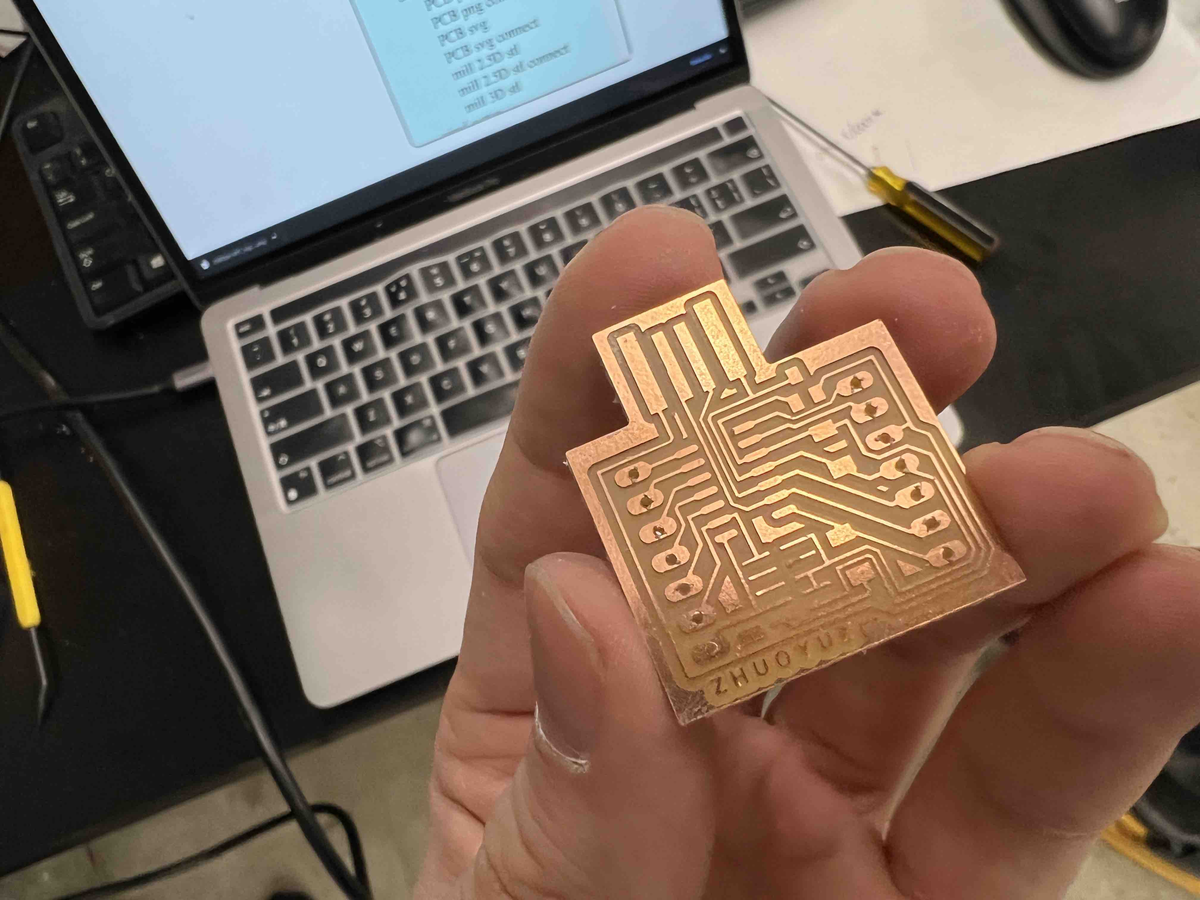
Using D11C to Extend the Pins
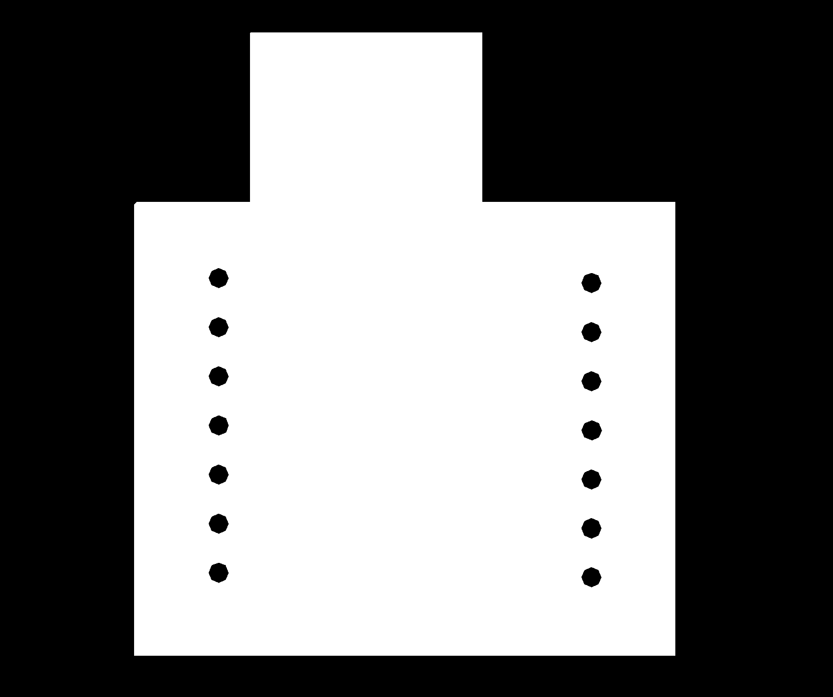
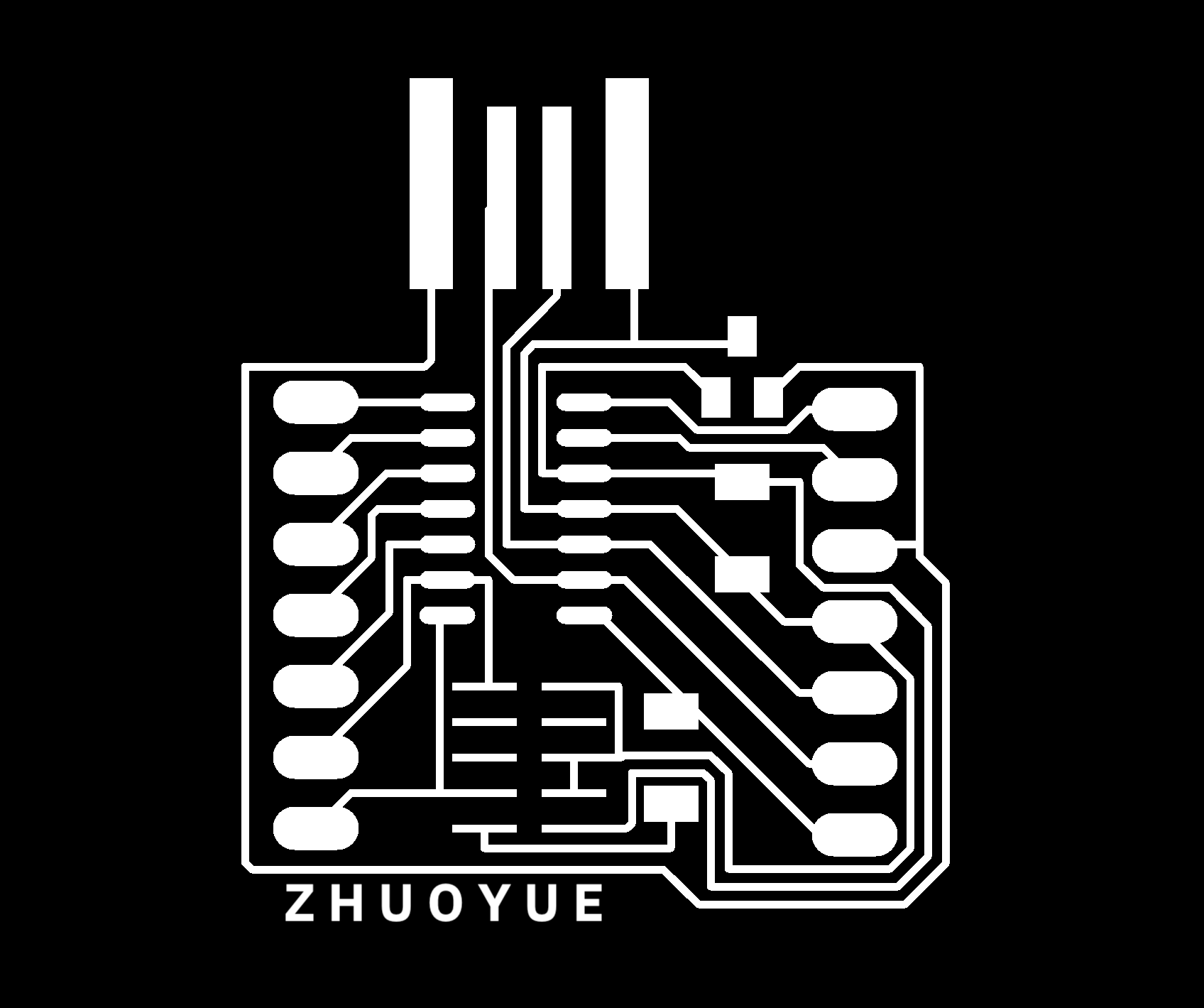
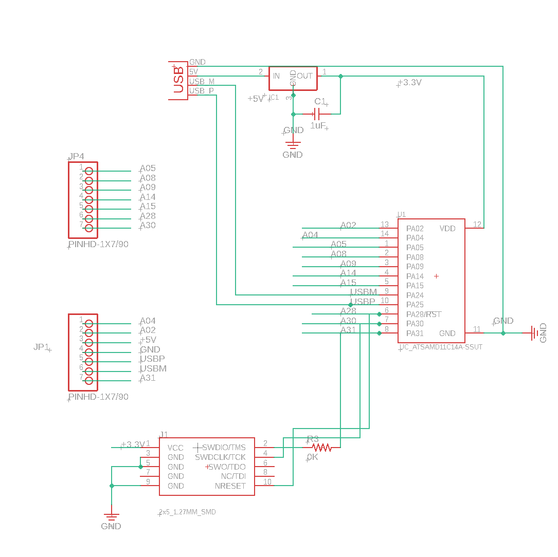
Lingdong suggested I use D21, but since I noticed I only need 8 pins, D11 might be enough (and easier). Therefore, I pulled up the design files for D11C that I created weeks ago and started to modify it. At this point, I didn't really know whether I should use TX1 or TX2, and I wanted to make the board reusable for future projects, so I basically added headers for all the pins.
While designing the files, I noticed I couldn't put holes on it. Therefore I decided to draw it on a seperate layers, which works very well. First draw hole in the hole section (draw circle) than change to layer 19. "Define your group, on the command line type "CHANGE Layer", select the layer you wish to use. Now do a RIGHT click anywhere within the defined group, and select the option "Change:Group"." (link).
To export the image as PNG, follow this tutorial (link). You would
need to select the layers you need
and then export image. But be careful, if you have any labels in the design, move them
inside, otherwise the exported image will have wrong size. Also, for the outline, right click
polygond, will fill the board area. Otherwise the inside is gonna be black instead of white
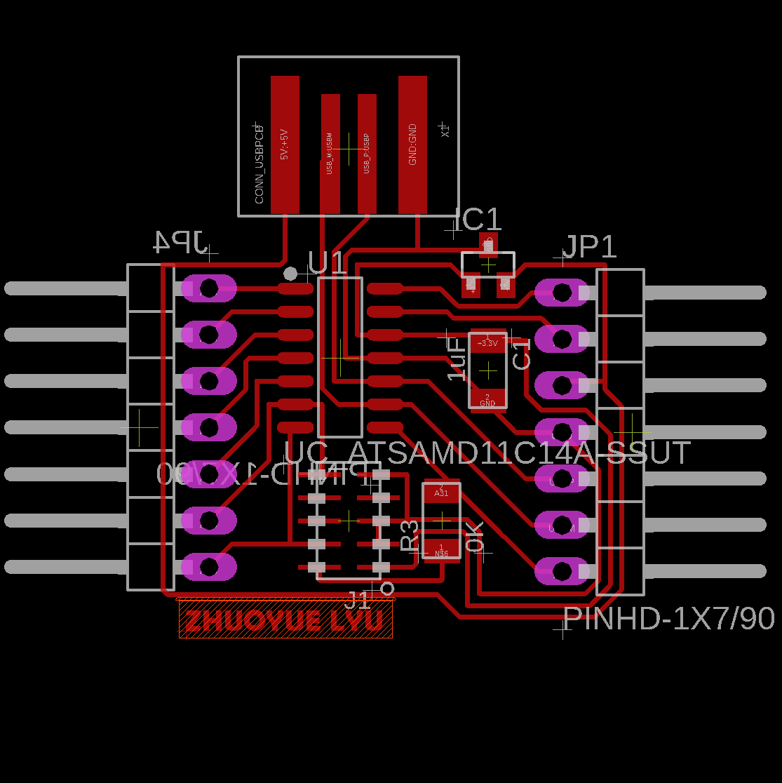
This time again, I didn't use the line/pad spacing recommended by fab (16 mil), because I want to make the wires go under components (for example, four wires under D11C) which needs 13-15 mil to achieve. But this step means we would need to adjust the space in the mods according, which I will discuss below.
Finally, make sure the top and bottom have enough black area. The first time I made it, the white USB part was too close to the top. Nix said this way. The mods will not recognize it. Therefore he helped me pad it in the PS.
Milling (Fixing machine for everyone)
I was trying to mill my board, but Noy said the milling machine in SC102 was down when she tried to connect the monitor to her board. Sondos showed me the room next to SC102 where there is another milling machine (I never knew this). But Selin was using it.
Unfortunately, Selin's jobs failed multiple times. Therefore, I decided to fix the milling machine myself. After 2-3 hours of endeavors, I fixed it! Turns out the Linux system that was newly installed needed a few libraries. Also some common errors that the fab website (link) has provided lots of insights. After I fixed it, it seemed that everybody was happy

I created a document (link) for using it because the workflow is slightly different.
Anyway, when setting the milling parameters, I set it to 0.0113 (instead of
1/64=0.015625) because,
as I mentioned previously, I used a smaller wire/pad distance. This makes the tool think they are
smaller than they are, so it can get those little details. But the problem is, that the actual tool
size doesn't change. The final result will have thinner wires than that you designed, which might be
hard to solder. But I'm okay with that.
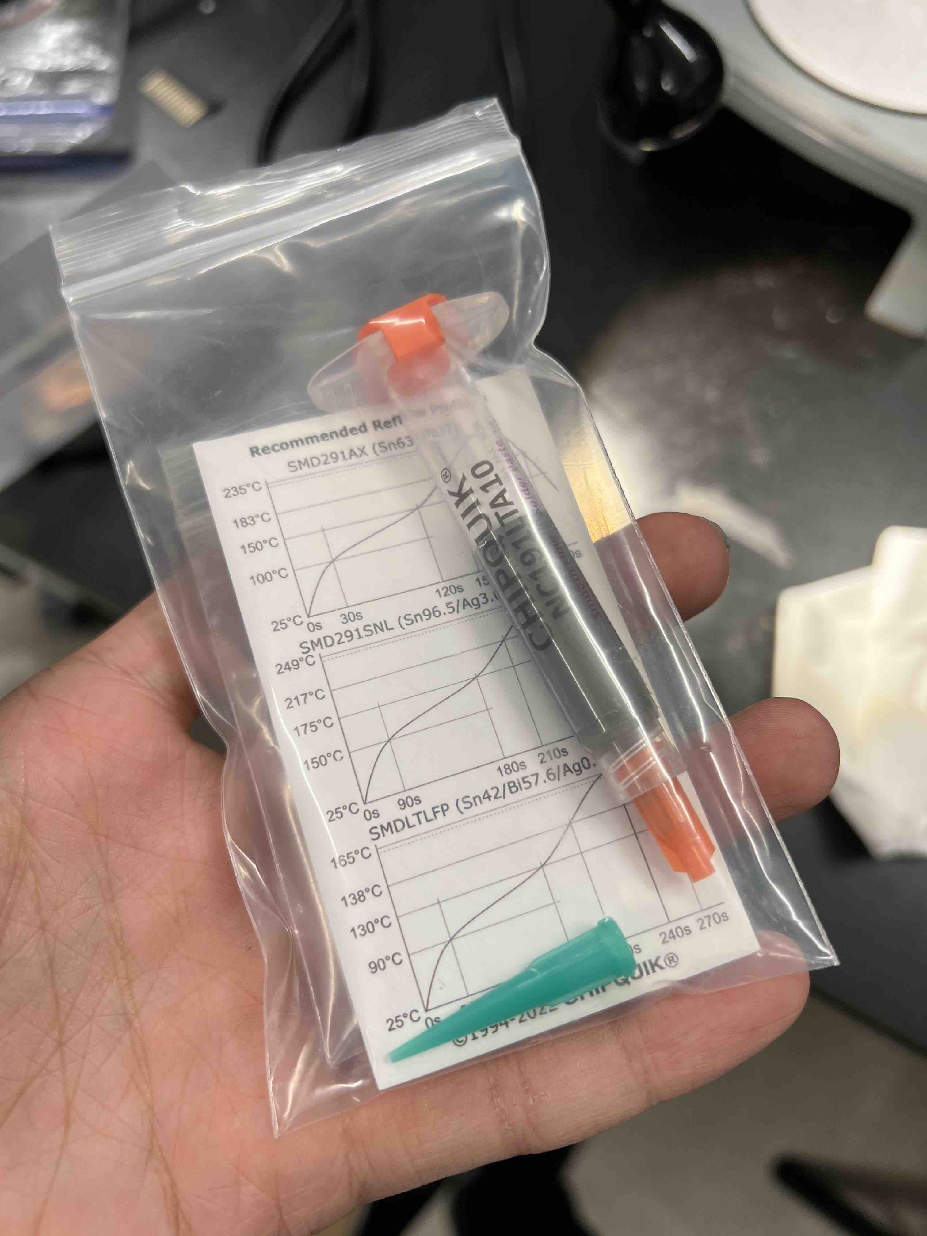
Soldering (Used paste & microscope for the 1st time!)
I used the paste for the 1st time and it was sooooo good. You basically put the paste anywhere you want. After you heated with the heat gun (300-400 degrees temperature), it's going to contract around the pin & copper, so you don't need to worry about anything! ( you do need to hold the piece in place though, to prevent it from being blown away by the heat gun)
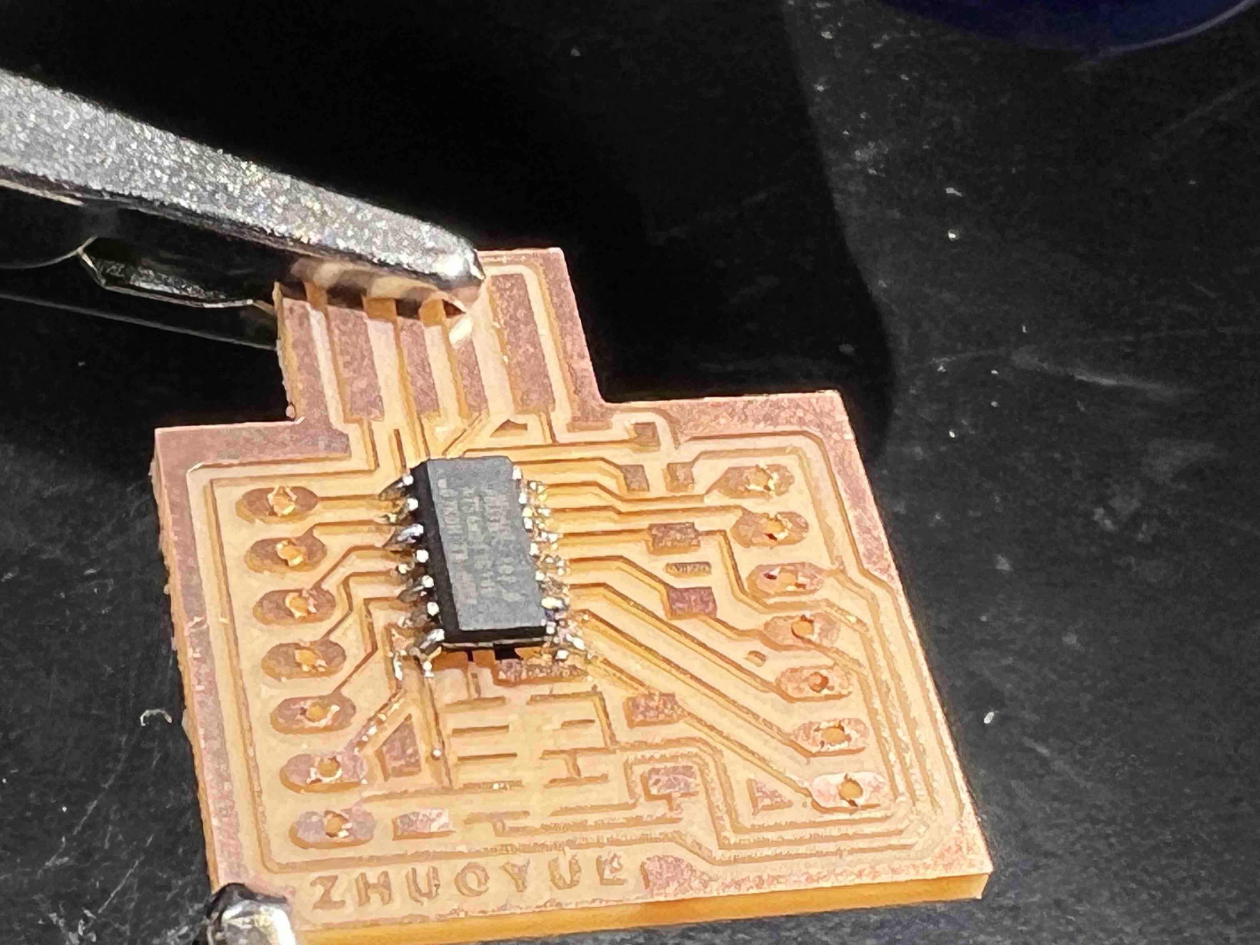
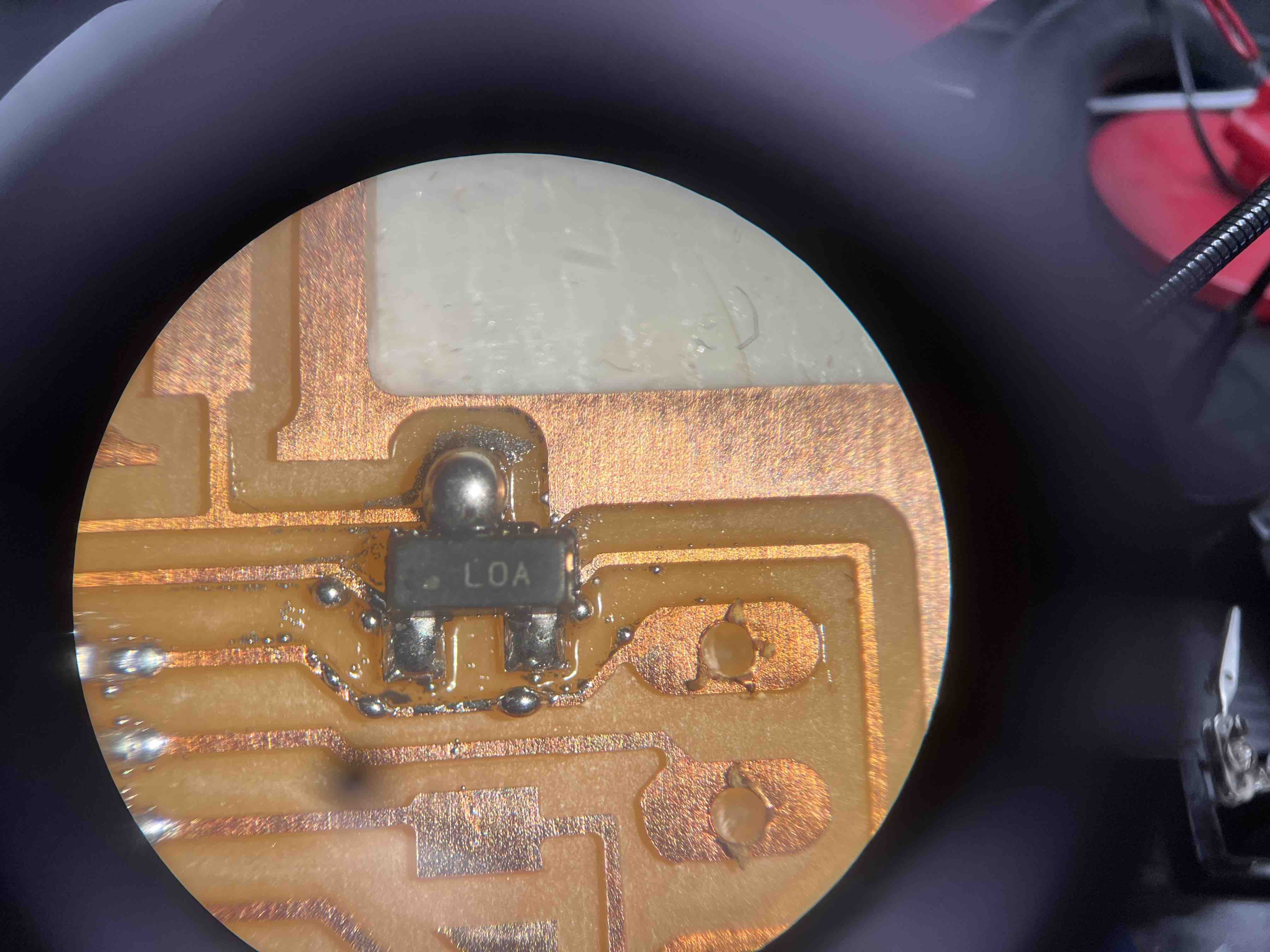
The microscope is great as well, good for checking whether the solder attaches well and whether there are some broken wires.
Programming
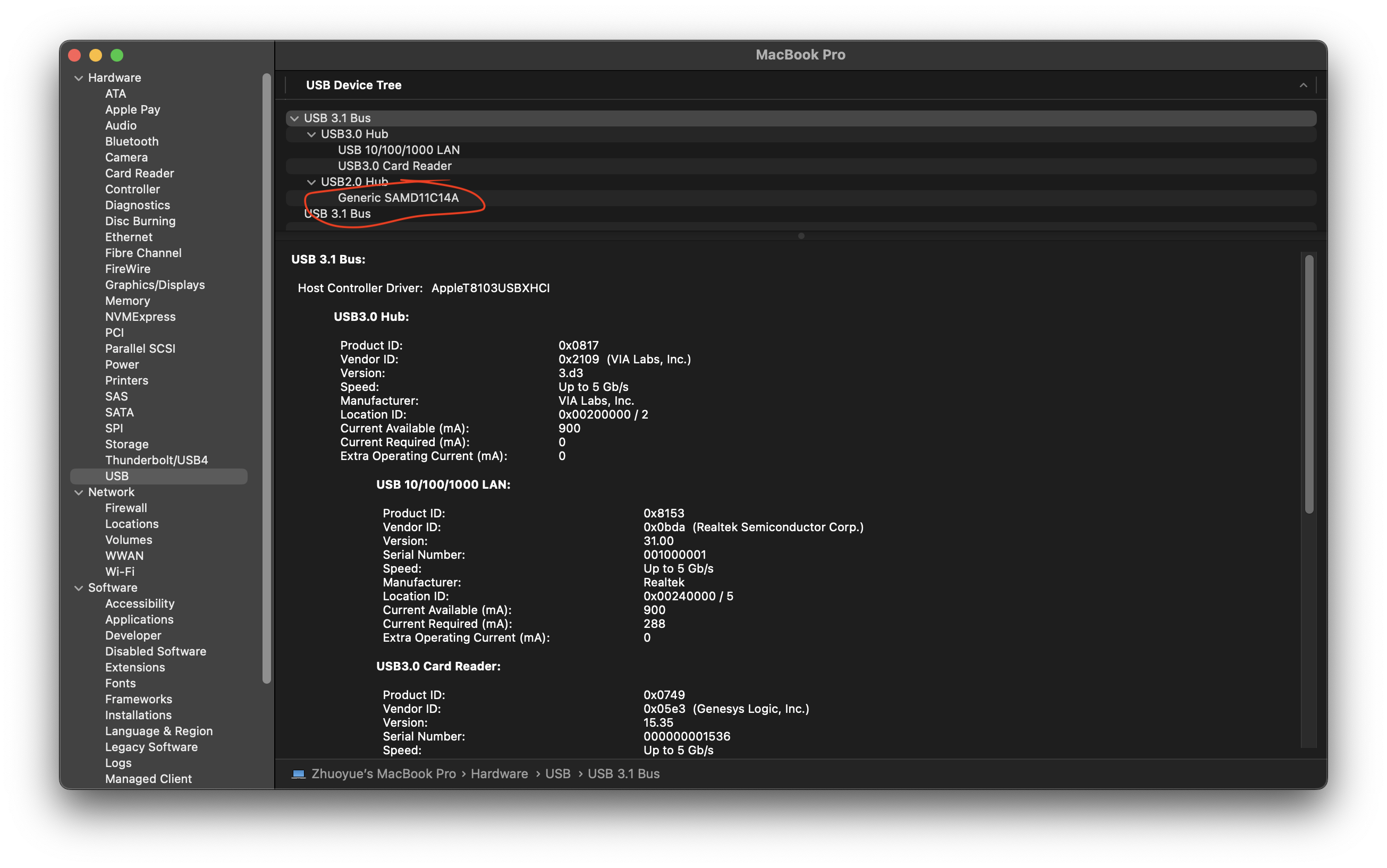
Following the same step weeks ago, I spent a really long time but couldn't get it recognized as D11C, and it was always recognized as an adapter. (and it actually failed several times, but I noticed it's probably just the USB connection issue, because it eventually worked).
Later I realized, I need to change the .bin file! The .bin file used in the
electronics production week is different! We need to use this
.bin to make it recognized as D11C!!! I wasted 2-3 hours on this...
Serial/Wifi Connections
The serial/wifi connections is documented under Week 11 - networking and communications
Useful Links-
- How to program?
-
- This project used ESP32-CAM to control two servo...
-
https://youtu.be/Gza4io7Lmlo?t=533
- it seems that the built in face recognition system does not detect multiple faces at the
same time...

- it seems that the built in face recognition system does not detect multiple faces at the
same time...
-
- Shows how to setup/program the board
-
https://randomnerdtutorials.com/esp32-cam-video-streaming-face-recognition-arduino-ide/
- Similar tutorial
-
- Object Detection & Identification using ESP32 CAM Module & OpenCV
- https://how2electronics.com/esp32-cam-based-face-eyes-recognition-system/
- but this one runs using the computer instead of ESP32 itself
-
- It’s possible to run OpenCV on ESP32!!!
- Code https://github.com/joachimBurket/esp32-opencv
-
- Face recognition using ESP32
-
http://fab.cba.mit.edu/classes/863.21/CBA/people/catfang/hw/week10.html
- ESP32's footprint in the FAB library is too big. Make sure to modify SizeY (width) to 0.6mm instead.
- make sure there is nothing underneath the esp32 antenna
- To program the ESP32-Wroom, you would first need to
ground the GPIO0andpress the resetbutton so that the board is ready for receive the code. - Her mistake: "GPIO0 pin isn't actually connected to the copper trace underneath!"
- Grabbed the 5V regulator instead of the 3.3V since they look identical except for the tiny text on top
- https://youtu.be/rGEI4u4JSQg
-
https://www.thingiverse.com/thing:5457127
- Shinsaku Hiura's Work!
-
ESP32 driving motor
Should think about:
- 5V or 3.3V regulator?
- Make sure all pins soldered properly
- heads (connectors) are strong (how?)
-
https://fab.cba.mit.edu/classes/863.21/Architecture/people/YanjunEmilyLiu/week10.html
- Talks about how to program a ESP32 board
- Use FTDI cable is better than using the FTDI board
- Also talks about connecting tx and rx pins between two ESP boards
- http://academy.cba.mit.edu/classes/networking_communications/ESP32/hello.ESP32-WROOM.png
- has the board design, but I notice all the pins are wasted
- http://academy.cba.mit.edu/classes/networking_communications/ESP32/hello.ESP32-CAM.jpg
- Or I could probably use this ESP32-CAM?
- https://fab.cba.mit.edu/classes/863.21/Architecture/people/demircantas/week10.html
- This one has the bottom board designed as well..
- http://fab.cba.mit.edu/classes/863.19/Harvard/people/donagh/network.html
- Document the whole process with ESP32 CAM
- https://fab.cba.mit.edu/classes/863.21/CBA/people/raechel/week9.html
- I realized that it didn't mill the holes
Files