Output Devices
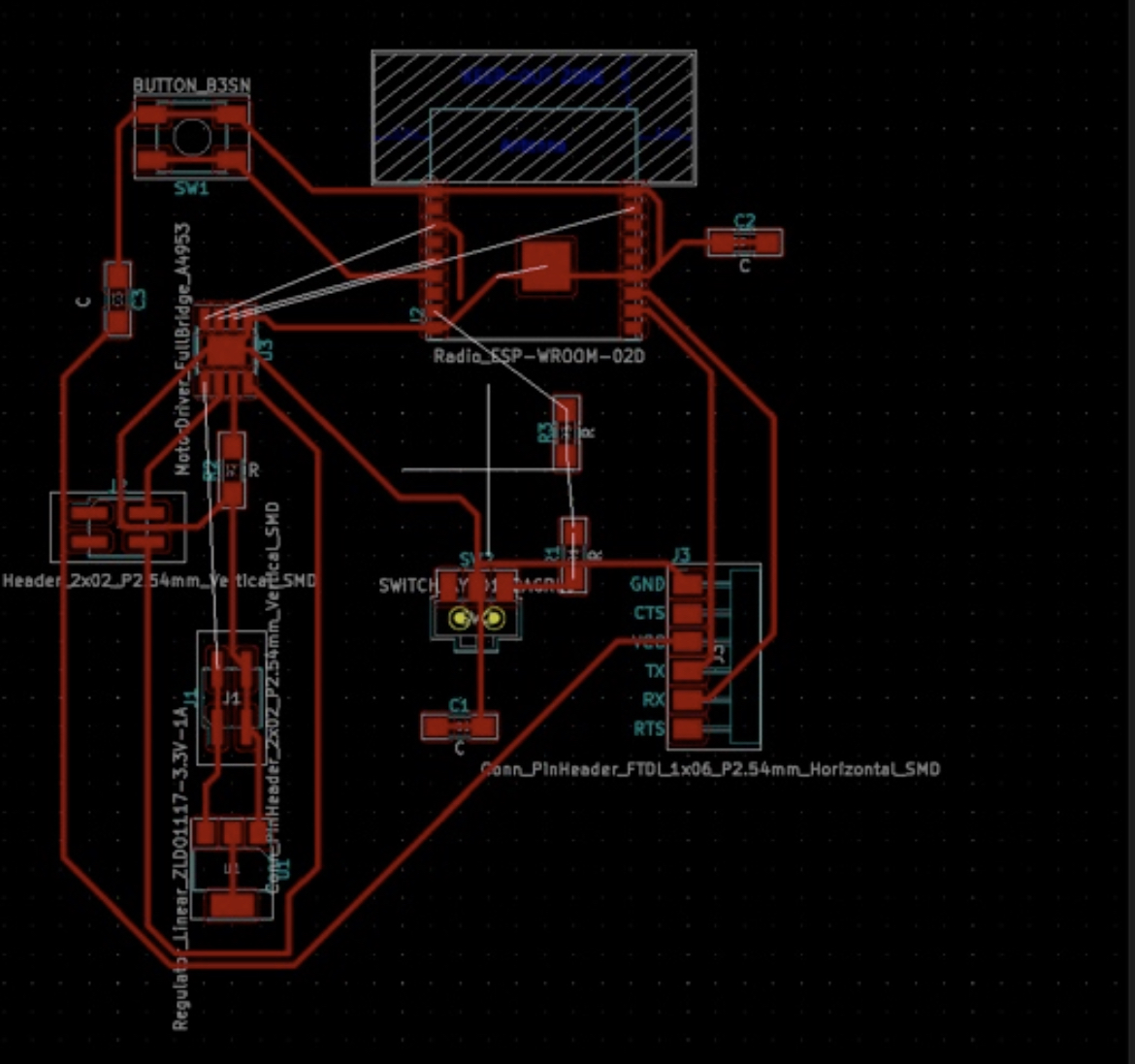
This week, we had to add an output device to a microcontroller board we have designed, and program it to do something I used a DC motor and an A4953: Full-Bridge Motor Driver. Fortunately, I was able to use the same board. Here are the steps that I took to make that board from last week: I used KiCad to design the board. This process took a lot longer than I expected because I had to design and then redesign the board two times. This took me a very long time to design because I still struggled to understand the logic of when to add a capacitor or connect a trace to ground. Nevertheless, I finally understood the purpose of jumper resistors and capacitors. So I'm happy that I'm learning the logic of what I'm doing. The first time I used the incorrect ESP32-CAM footprint. I mistakingly used the Radio_ESP-WROOM-02D. I found the correct footprint on SnapEDA. Here is what my design looked like before I replaced the footprint.
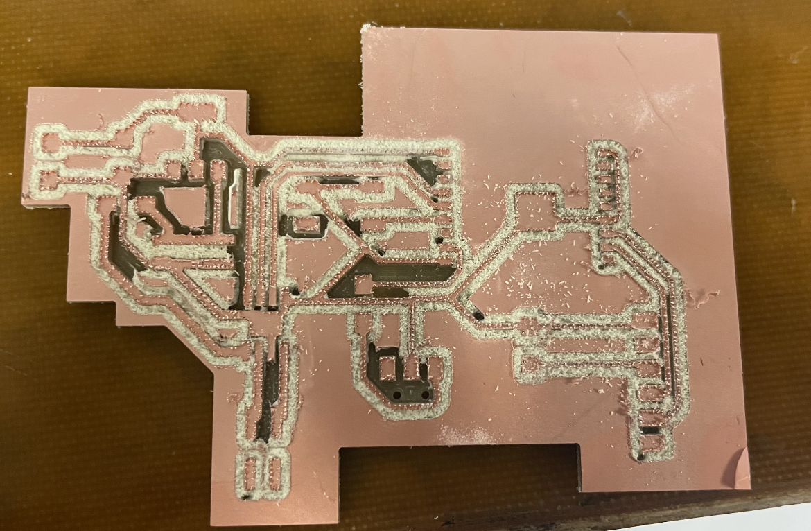
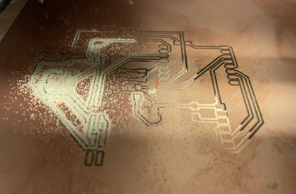
Unfortunately, I didn't figure out this mistake until after I finished milling the board two times. :(Good news: I did get a lot more comfortable with the milling process. The first time that I milled the board, I think the end mill broke, which resulted in a board that looked like this:
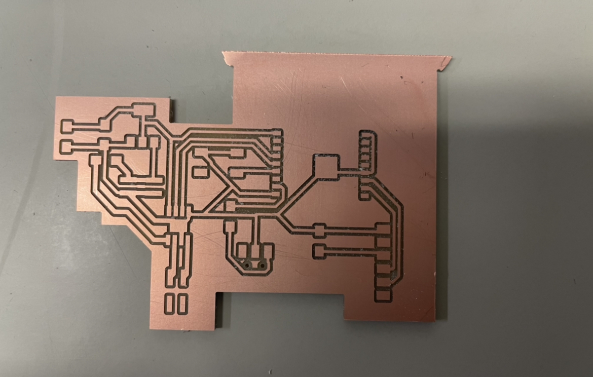
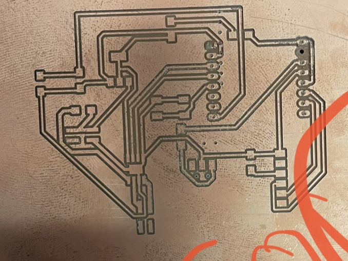
After I changed the end mill, the board milled correctly:
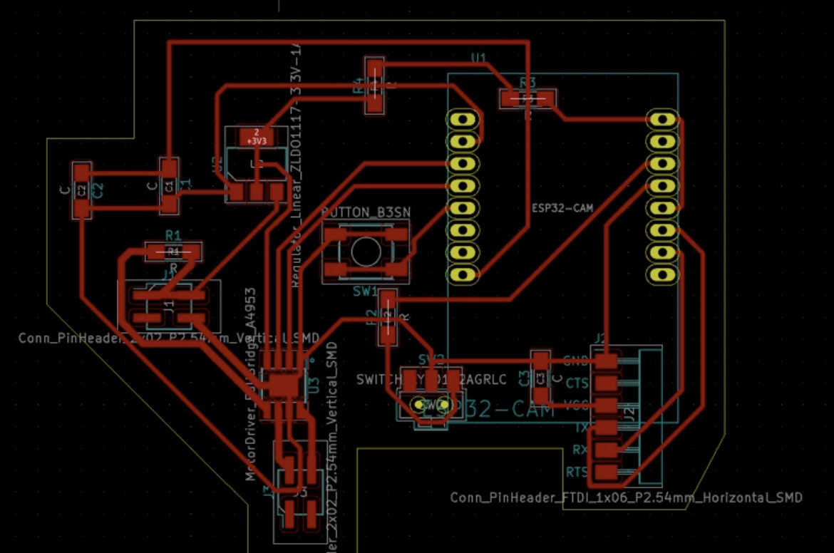
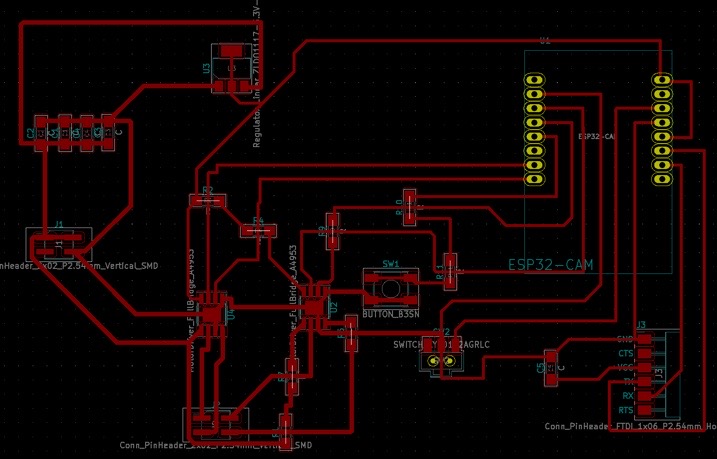
While I was putting on my components, I realized that the ESP32-CAM footprint was incorrect. This mistake could have been avoided if I looked at the ESP32CAM that was in the CBA and compared the number of legs to the number of legs on the footprint. After, I discovered this mistake, I had to redesign the board, which took me a while because I'm still new to this. Here is the final board and schematic:
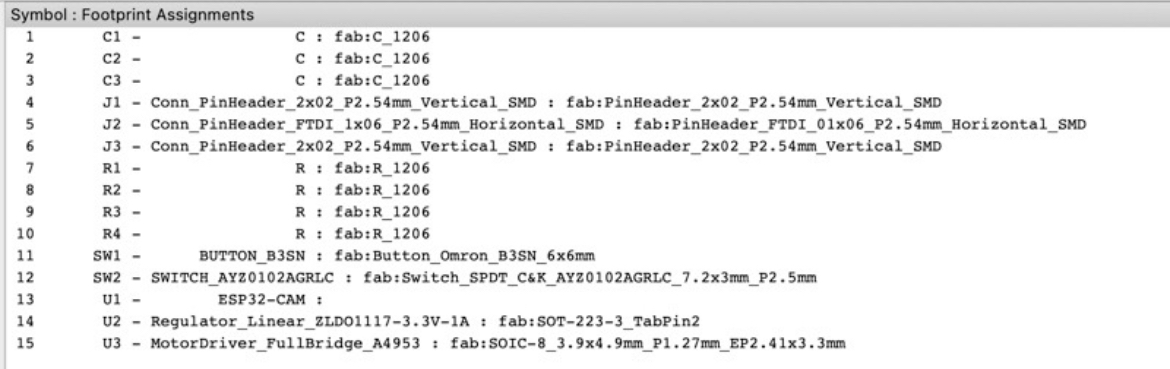
Here are the final components that I used:
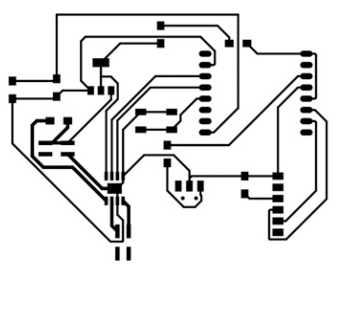
Here is the final board design on KiCad:
 After I had the final board design, I exported everything to Inkscape again and I started the milling process. The first time that I milled the board, I had the wrong cut depth, so the board didn't mill all of the way.
The next time that I milled the board, I realized that it didn't mill the holes. So I tried to export the bottom layer from KiCad as an SVG, then use Inkscape, then mill the board. Unfortunately, the holes were not aligned with the footprint.
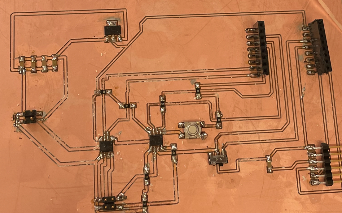
So David suggested that I copy and paste the holes(the bottom layer in KiCad) to the Inkscape with the footprints, so that I can ensure that the alignment was perfect. Thankfully, this worked! Yay! I finally had a board design:
Unfortunately, this was only the beginning of a lot of problems with my board. Once I realized that I wasn't getting 3V3 volts out of my regulator, I tried several things (which took several hours to debug. Thank you to Andres, Zack, David, and Anthony for your help!): (1) changed the resistors to 0 ohm resistors, (2) used a razor to cut traces near the jumper resistor, (3) desoldered the ESP32-CAM.
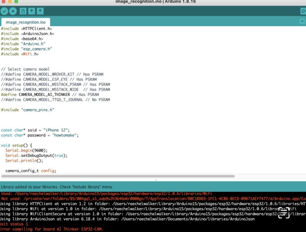
After this huge lesson, I still received the following error when I tried to upload the code "Failed to connect to ESP32: Timed out waiting for packet header". I used the CameraWebServer example on Arduino. I mainly just changed the code so that it connected to my hotspot. As a result, I followed a bunch of tutorials about resetting the ESP32-CAM and troubleshooting and moving the switch on and off(such as holding the BOOT/FLASH button until it flashes a couple times, holding the BOOT/FLASH button until the Arduino IDE says "connecting...", holding the BOOT/FLASH button until it is done uploading) from these websites: https://randomnerdtutorials.com/installing-the-esp32-board-in-arduino-ide-windows-instructions/ and https://randomnerdtutorials.com/solved-failed-to-connect-to-esp32-timed-out-waiting-for-packet-header/, but I could't seem to find a pattern for how to ensure that the code actually finishes uploading all of the time.
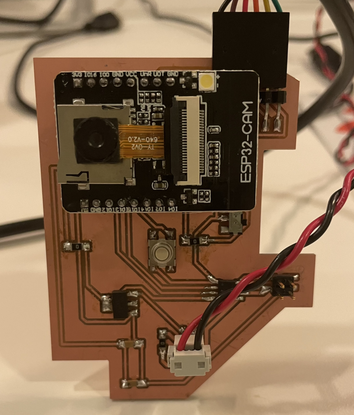
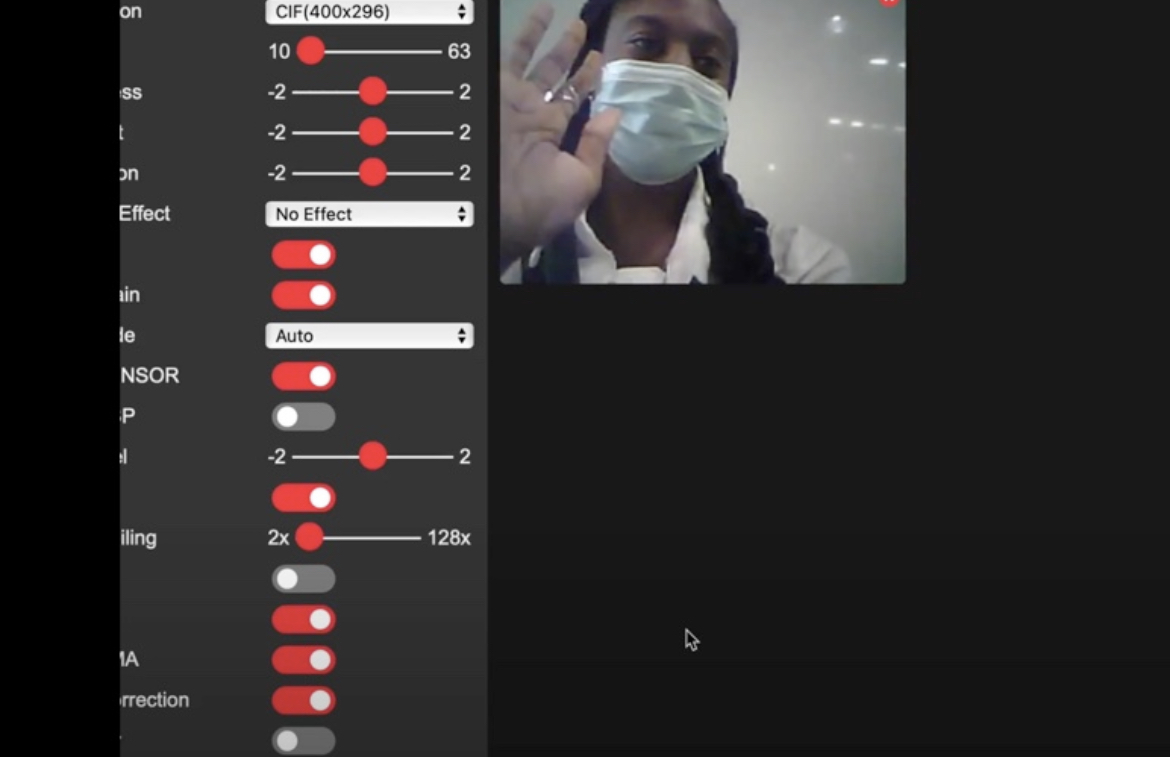
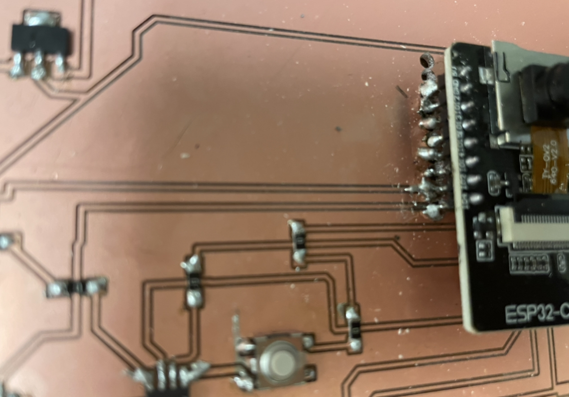
This is where Andres was a huge help. He suggested that I resolder the resistors and added some sort of copper adhesive tape because some of the copper was taken off when I desoldered some of the components. Unfortunately, it wasn't double sided copper tape, so he showed me how I needed to make sure the solder was around the tape. After using the voltmeter to check all of the traces on the board, we dedcided to replace the ESP32-CAM and add copper tape to parts of the board that came off. Next, I tried to upload the code again, but to no avail. After a few more tries,I realized that I needed to consistently check that my hotspot was connected and Voila! It started to work. I could finally take pictures, and stream videos. Yay!
Also, I started to do this tutorial about image recognition for my final project, but I ran into some errors:
Link to image recognition tutorial
Then, I soldered two wires onto the DC motor and connected the corresponding pins to the board.
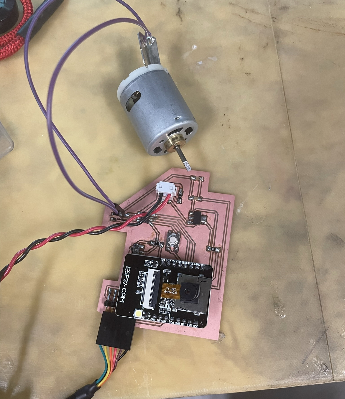
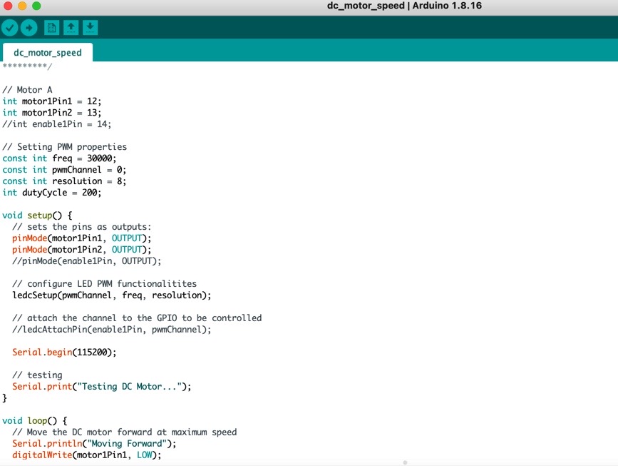
The code that I used for the DC motor was found on randomnerdtutorials. The code moves the DC motor forward at maximum speed, stops the DC motor, moves the DC motor backwards at maximum speed, stops the DC motor, and moves the DC motor forward with increasing speed.
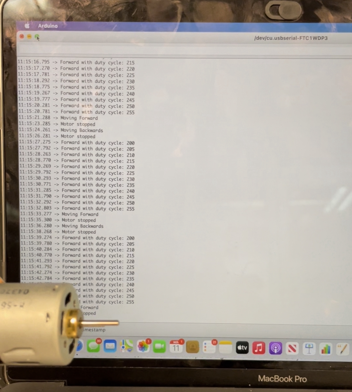
Here is the link to the DC motor working.
Next, I decided to work on my final project. I redesigned my board because I was getting a shortage. Since, I'm creating a robot that can navigate itself through a maze I decided to add two motor drivers to my board. Here is my schematic and board. I was able to solder this board, but to no avail. Unfortunately, the first time that I milled the board, I couldn't figure out how to solder the ESP32 because I made the holes too big. I think the holes were too big because I didn't invert the SVG file. I decided to not create the holes for the ESP32-CAM.As a result, I milled the board again, but to no avail. I was getting another shortage. Anthony reccommended that I make the traces larger by changing the offset from 1 to 4. I am in the process of doing this now.
images
Link to output devices files