final project
vr cockpit simulator
-
welded steel frame
-
adjustable chair
-
mfd button bezel
-
mfd test interface
chair + frame design files (STEP)
Seat model viewer:
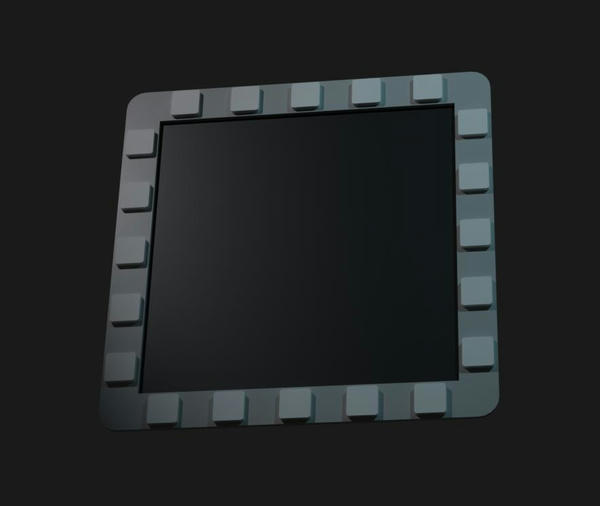
MFD model viewer:
Early render (previous revision):
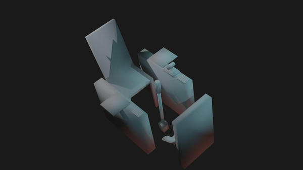
I built a flight simulator cockpit designed for VR. It integrates:
- Position-adjustable mounts for components I had prior to the class (flight stick, throttle, rudder pedals)
- Multi-function display ("MFD") button bezels that present to the host computer as 25-button gamepads over USB
- A highly position-adjustable seat, supporting independently setting:
- The height of the front of the seat
- The height of the back of the seat
- Seat back angle
- A test interface for the MFDs
Problems I'm solving:
- Setup and teardown cost of my existing peripherals is high (attaching/detaching to desk and putting back into storage). I want a fixed, desk-independent setup where everything is in position by default.
- Using rudder pedals for an extended period of time in a normal chair causes you to lean back on your tailbone. Not ergonomic over any meaningful amount of time -- chair is adjustable to allow me to find a reasonably comfortable sitting position.
- For similar reasons, control manipulator (throttle, rudder pedals, joystick) position is important relative to sitting position -- these should be finely adjustable.
- VR-controller-based cockpit interaction is very clunky. I want physical buttons instead, where possible. MFDs are the clearest pain point -- I use them a lot to interact with menuing, and they're impractical to bind to existing surplus buttons.
prior art
There is extensive prior art in building simulated cockpits online. A conceptual inspiration for me is The Warthog Project, building a simulator for an A-10C II Warthog, who I've watched extensively on YouTube.
Worth also putting in this section that I already had my primary flight controls before even starting the class and had desk mounts for them.
production summary + bom
seat
- MIG welded steel tube (1.25" OD x 0.125" wall thickness, ~30' from CBA shop stock)
- FDM-printed bearing and interface blocks (PLA, produced on ResEnv Prusas and my personal Ender 3)
- 1/2-13 threaded rod (Amazon, $13 per 2), with nuts and washers
- M8 and 5/16" (nearly the same OD, so functionally interchangeable in my project) bolts, nuts, and washers (various lengths, some from Amazon, some from Home Depot)
- 8mm ground shaft -- Amazon
- Skateboard bearings (8mm x 22mm x 7mm) -- Amazon
- Latex foam matress topper (seat, unknown provenance -- received for free)
- 3/4" plywood (seat, unknown provenance -- received for free)
flight controls (i already owned, all from virpil controls)
- MongoosT-50CM2 Grip
- MongoosT-50CM3 Stick Base
- VPC Flightstick Extension (200mm)
- MongoosT-50CM3 Throttle
- VPC ACE Pedals
mfd panel
- 22ga sheet steel (cold-rolled), lasercut and hemmed in CBA shop (see wildcard week)
- FR1 copper boards, double-sided (SparkFun) -- milled on ResEnv PCB mill with 20 deg v-bits
- FDM-printed MFD frame (PLA, ResEnv Prusas)
- M4 heat-set inserts and machine screws (from ResEnv inventory)
- 12mm momentary buttons (from ResEnv inventory)
- SLA-printed button heads (ResEnv Form 3, Clear V4 resin)
software
- Autodesk Inventor (CAD)
- OnShape (CAD, switched from Inventor)
- KiCad (EDA)
- Blender (misc renders)
- Arduino (controller firmware)
- pygame (test interface)
mfds
Early concept:
Summary
"Multi-function display" -- displays in cockpit with buttons around them that a pilot can press for various menued functions. Since I fly in VR, I don't need the display element itself, just the buttons.
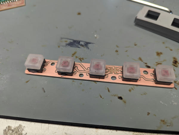
I designed the MFD in 4 modular parts that fit together with dovetails. Each side mounts a PCB:
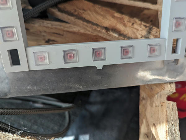
and has 5 buttons:
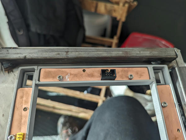
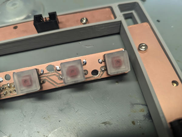
The boards interface with IDC connectors which are connected to a controller board. The controller is a RasPi Pico that reads the digital state of all of its pins and connects to a host computer over USB as a generic gamepad.
v1 (button boards + frame)
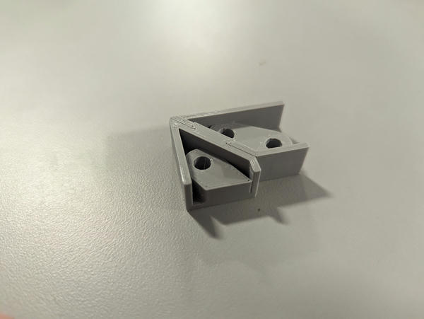
dovetails
I started by printing a test piece for the corner dovetails (zero offset made a nice tight fit):
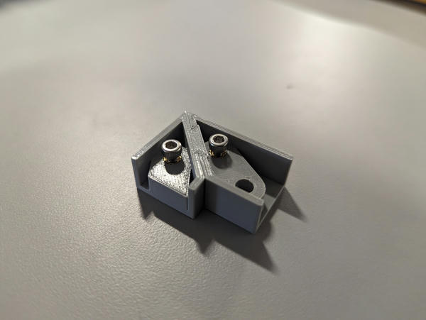
With heatsets installed and M3 screws:
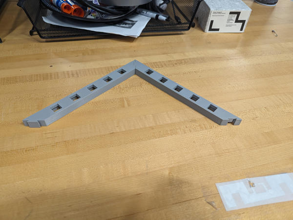
First version with full sides (wrong size, mitered corners):
button assembly
I printed heads for 12mm pushbuttons using the Form 3 out of clear resin:
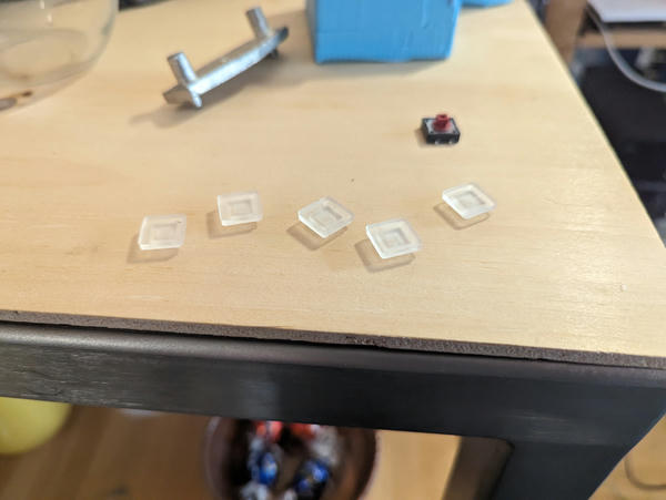
Assmbled:
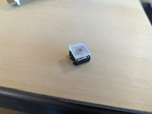
Zero offset was also just right for these.
pcb
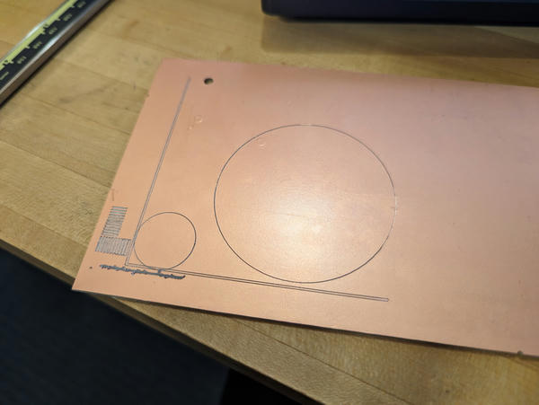
I transfered the relevant outline from Inventor and designed the boards to fit within the available space. I marked mounting holes where the heatsets would be.
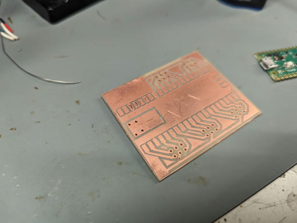
I did some test patterns because I was seeing axis-aligned inconsistency in my cuts:
First try was a bit fuzzy:
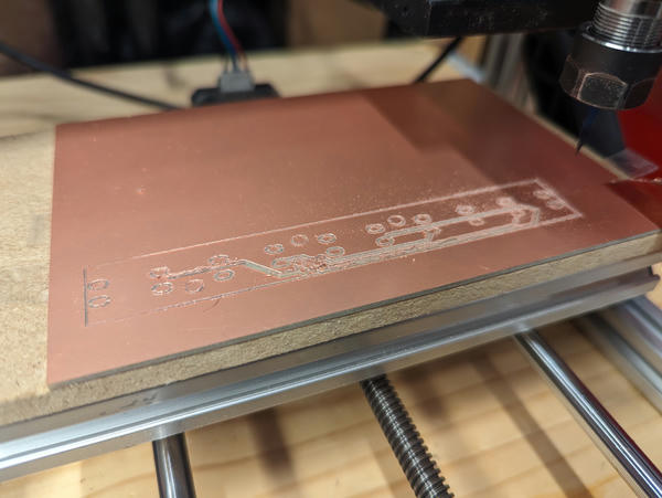
Some more attempts:
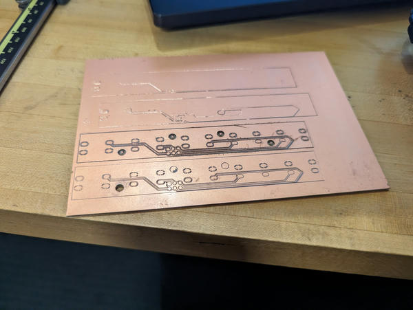
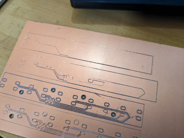
Finally a successful board:
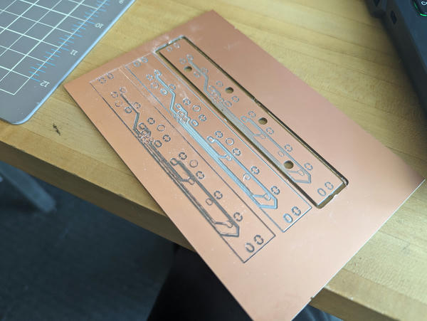
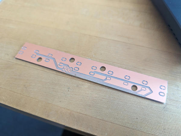
buttons (final)
The board needed a minor rev after I updated the layout of the controller board to change the order of the pinout. I also increased trace width and isolation to make the boards easier to mill and solder:
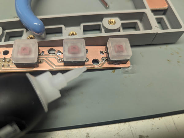
To get the buttons in the right spot, I placed them in the frame upside-down and put a dot of superglue onto each one:
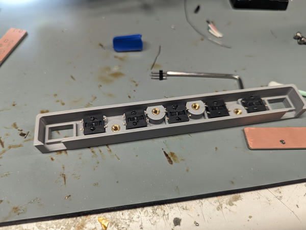
Then I screwed the pcb into the frame and let the superglue dry. I took the whole assembly out once it was dry and had the buttons in exactly the right place:
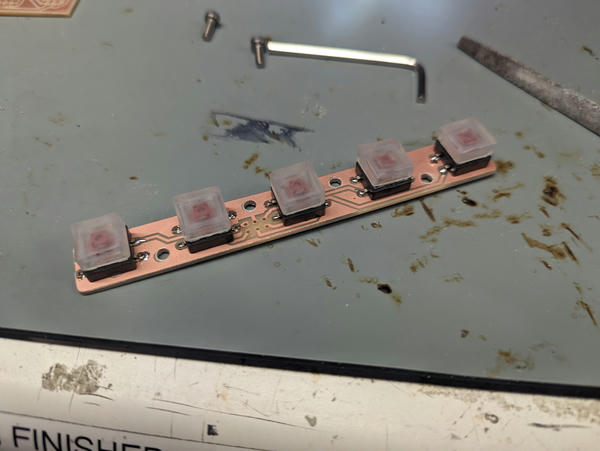
Then I soldered them:
I discovered eventually that all of the boards always reported button 1 pressed. This was because of this mounting hole (rightmost):
The threaded insert would short the ground plane to the trace next to the hole, making it look like the right button was always pressed. So I applied superglue as conformal coating:
This worked.
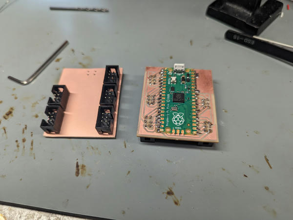
controller
Milled controller board:
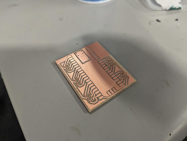
Cleaned up:
Forgot to individually isolate pads on pico reverse, so as in the button boards, applied superglue as conformal coating:
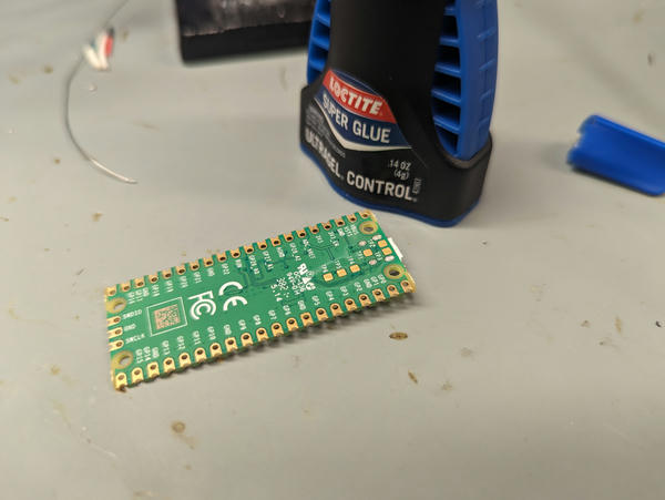
Pico soldered:
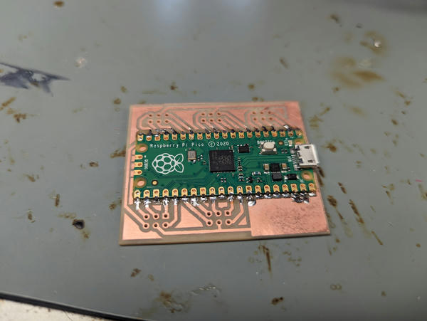
Assembled with IDC connectors:
You'll note I'm using 2-layer boards with through-hole components -- as I described in electronics production, I used a small drill bit (~3mm OD) by hand to chamfer / countersink the holes on the reverse side of the board so the pins wouldn't make contact. If you're deliberate about it, this approach is very consistent in ensuring the pins don't short to the back plane.
firmware
Uses the rp2040 port of the Arduino Joystick library to represent the mfd as a gamepad.
Very simple -- polling-based. Slight optimization I made that drastically improves
responsiveness is setting manual reporting and doing change tracking myself
— naive approach sends a USB packet for every button it scans.
Sketch here.
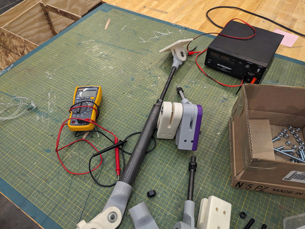
interface
I made an interface in pygame to validate the function of the MFD controllers.
This is functionally duplicative of the Windows gamepad tester -- I really only made this to fulfill the requirement that I personally implement the interface.
Plugging and unplugging a controller:
Shorting a button gpio to ground (emulating button press):
MFDs are hotpluggable and multiple are supported simultaneously:
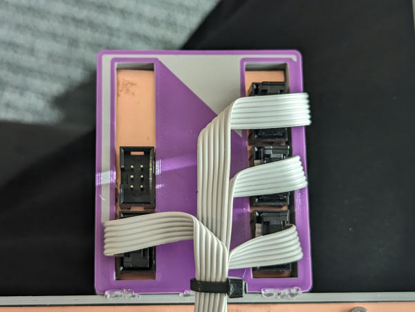
controller enclosure
I 3d-printed an enclosure for the controller out of PLA:
Cable routing (reverse):
frame
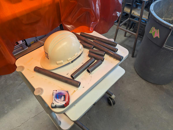
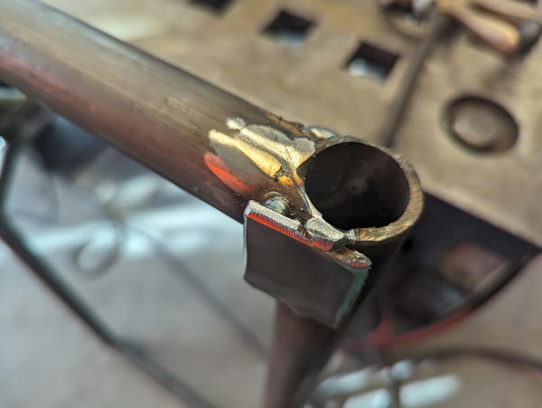
I made the frame out of 1 1/4" OD x 1/8" wall round pipe. I cut the pieces I need on the horizontal bandsaw:
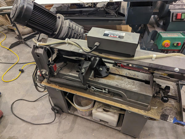
Result:
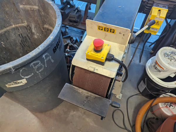
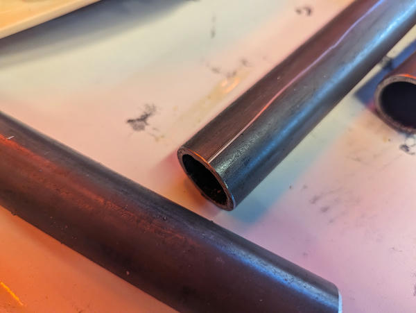
I chamfered them on the belt sander:
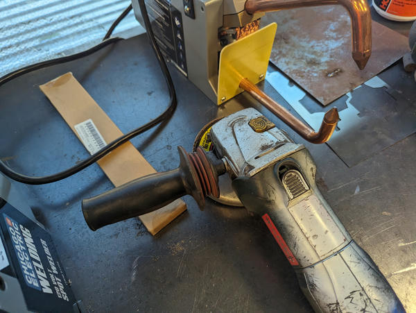
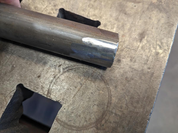
And used an angle grinder with a flap disk to clean the scale off the surfaces to prepare for welding:
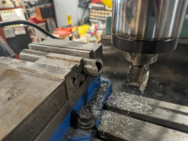
I milled cutouts on several of the T-joints to improve fitment:
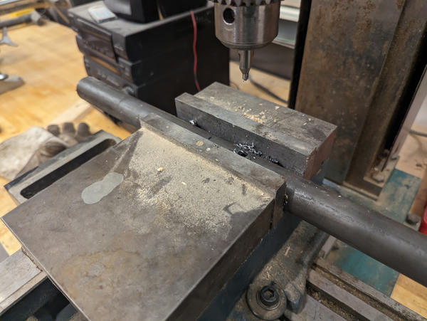
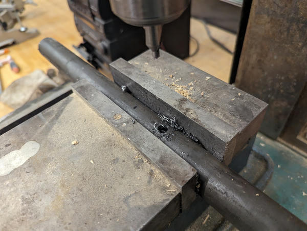
I needed through-holes in several parts, which I did on the drill press.
I didn't do a great job controlling weld heat, so the T-joints on the upright warped the frame upwards. I added feet made out of scrap to level the piece:
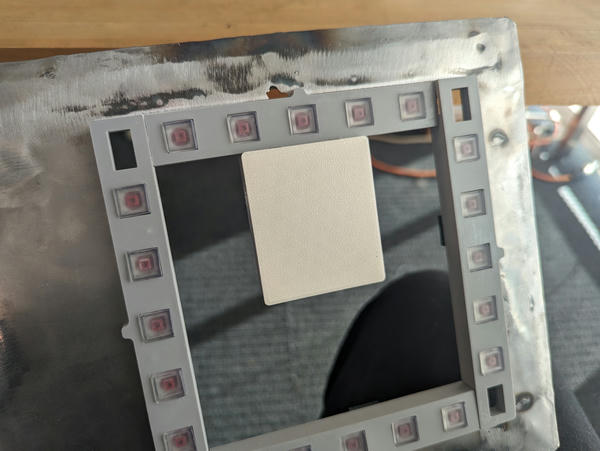
mfd front panel
I stiffened the front panel I made in wildcard week using MIG welding and some small square tube:
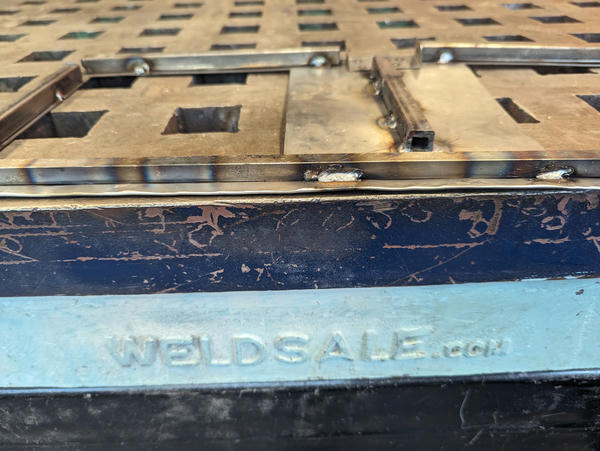
Obviously, it's not perfect -- nowhere close to rigid -- but I was able to take most of the warp out of it that I put into it from hammering the hem.
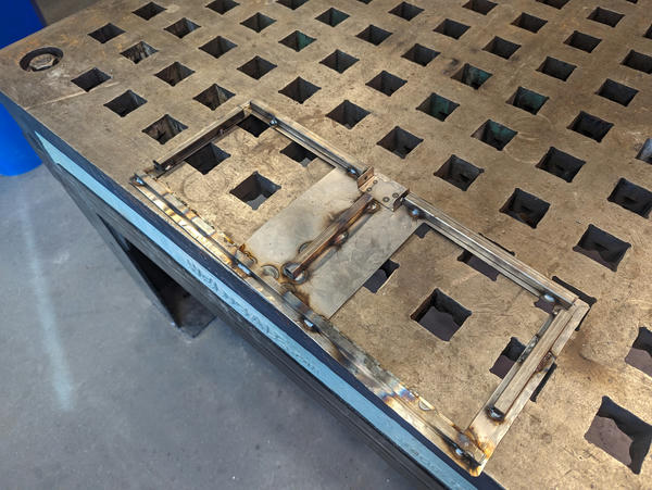
chair joints
The joints are 3d printed and have bearings pressed into them that ride on 8mm shaft.
The chair legs are height-adjustable via nuts on threaded rod.
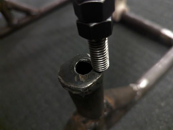
The top of the threaded rod is captured by a clevis block with a bearing that allows the connected part of the chair to move vertically:
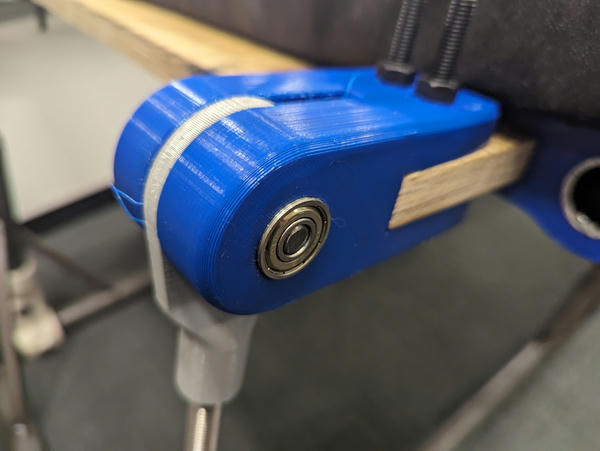
Together, these blocks permit fore-and-aft vertical adjustment of the seat base and angular adjustment of the seat back.
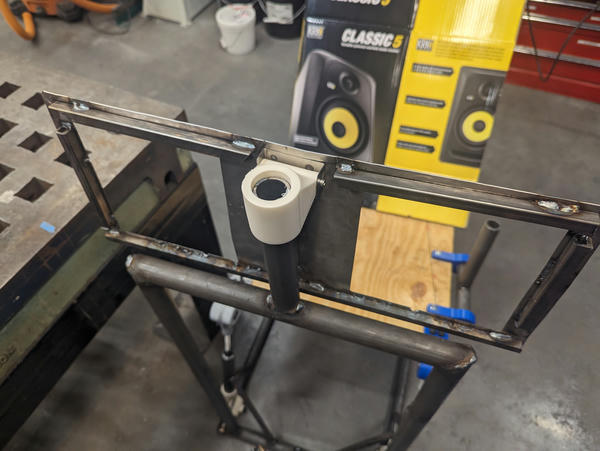
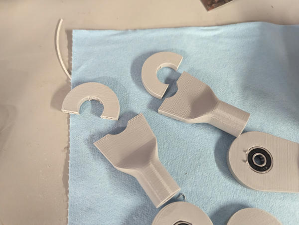
controls mounting
The controls mount with custom blocks that friction fit (tightly) onto the tube — adjusting the position of the controls means wiggling them on the tube they're mounted on.
This is the rudder mount being printed:
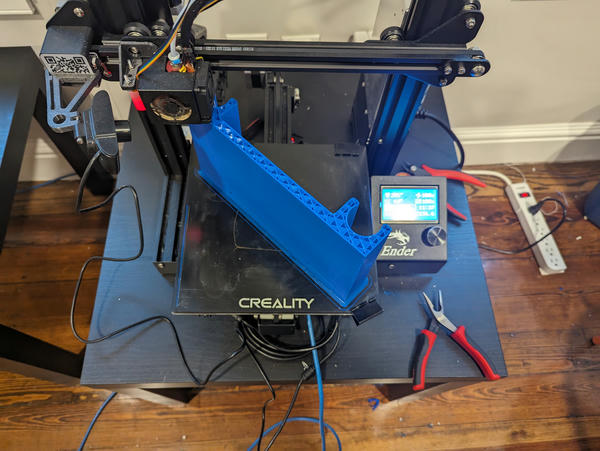
It is the one mount that needs to be tapped in with a hammer because there's so much contact area.
problems
racking
The clevis joints on the frame are nowhere near sturdy enough to resist racking laterally — I could tell they were going to snap. So I sacrificed a couple of degrees of freedom and welded the front of the chair in place. This made the chair sturdy enough, but still left me the back screws to adjust.
3d printing
broken heater
I mostly used Responsive Environments' fdm printers for my 3d printing needs. On one of them, the wires fatigued off of the heating element because the heater block wasn't screwed into the heat brake tightly:
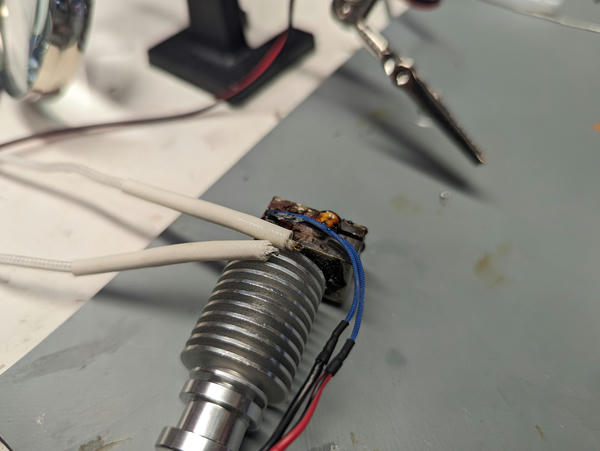
Brian and I fixed this up with spare parts he brought from home.
clevis split
These clevis blocks were printed in a convenient-but-weak orientation and split when I pressed bearings into them.
how evaluated
The project's internal evaluation norms are whether I'm comfortable in the seat and if it's sufficiently adjustable to put my body where it needs to be to use the controls, but the adjustability shouldn't permit it to move if I'm not adjusting it. I also needed it to be minimally portable (I need to be able to move it in my car).
The project succeeds on the comfort and portability axes — I built it for everything to come off of the frame, so it will fit in my car. The latex foam makes it very comfortable.
It's not perfectly stable — I didn't handle lateral stability well. I'm considering fine-tuning the position and then welding the back legs of the chair in place to make it fully rigid.
It doesn't entirely succeed on the adjustability axis either — I was able to get pretty close to what I want, but I put the uprights for the front panel slightly in the way of where my legs want to be to use the rudder pedals, and the joystick is too far forward (I may be able to fix this with more padding on the seat back).
implications
There are minimal procedural or research implications from the work — this was instead primarily a fabrication project and learning experience for me. Personally, the learnings are to simplify more aggressively, and intend + plan to iterate more.