Assignments
The individual assignments for this week are:
- design, build, and connect wired or wireless node(s) with network or bus addresses and a local interface
Wired Connection
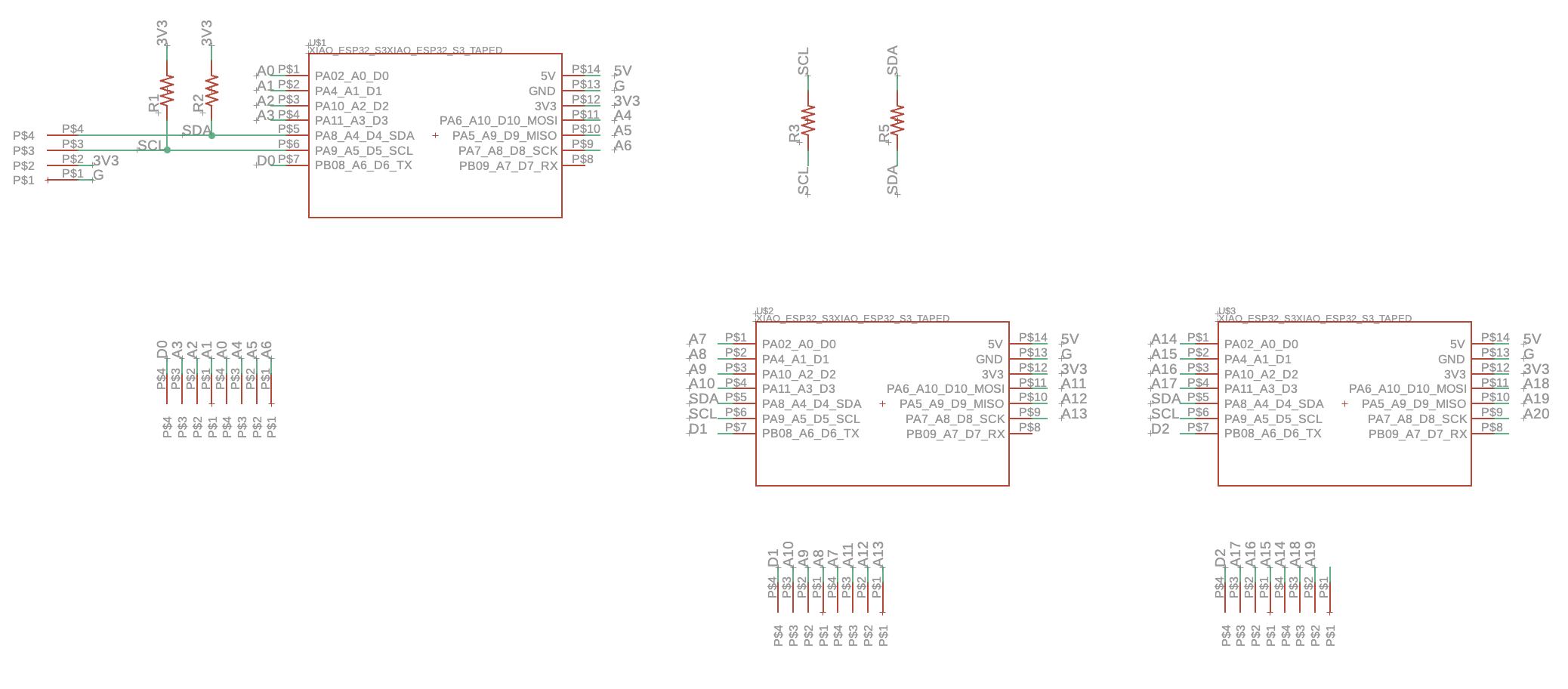
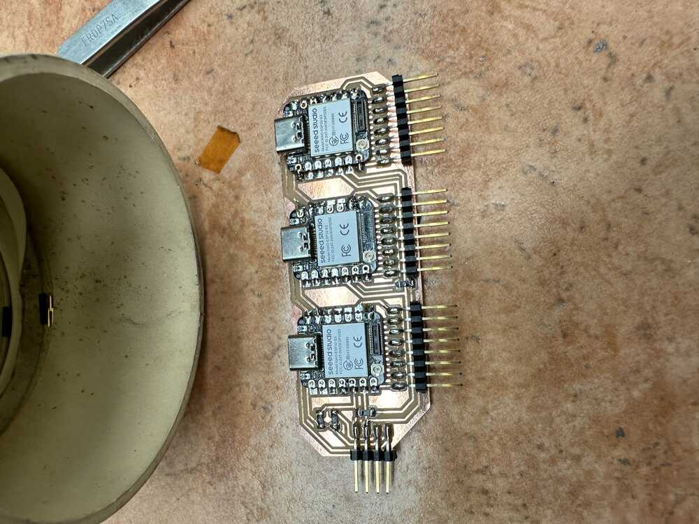
For this week, I designed a board that is designed to have 3 Xiao ESP32S3 microcontrollers, with each board talking to the other boards via I2C. The other analog pins on the board are used for capacitive step response, and the RX pin is designed to be used as the driving pin for the sensors.
The reason that I need three boards is that I want to have up to 21 sensors on my final project, and each board has 7 analog pins other excluding the SCL and SDA pins.
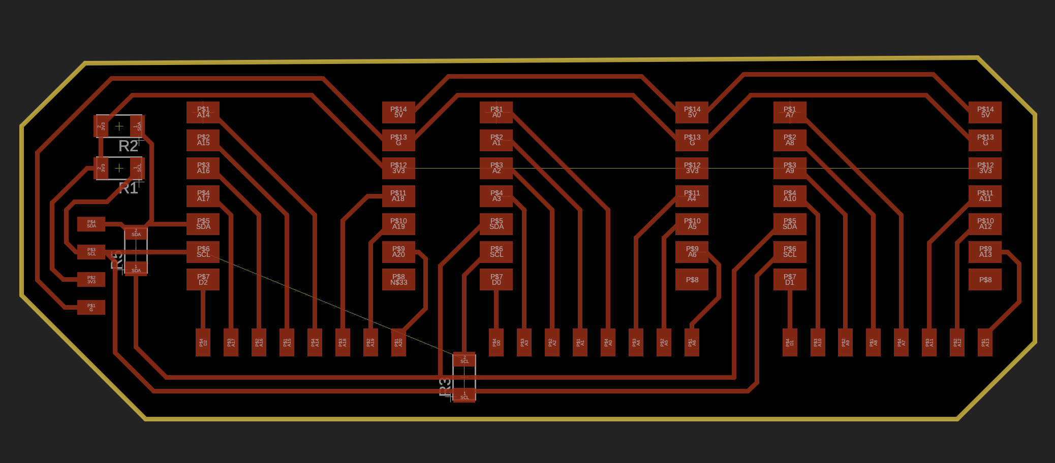
Importantly, the I2C pins are automatically connected by the traces on the board, and the board also has space for the pullup resistors needed for the I2C spec. I used resistors that were nominally 4990 Ohms.
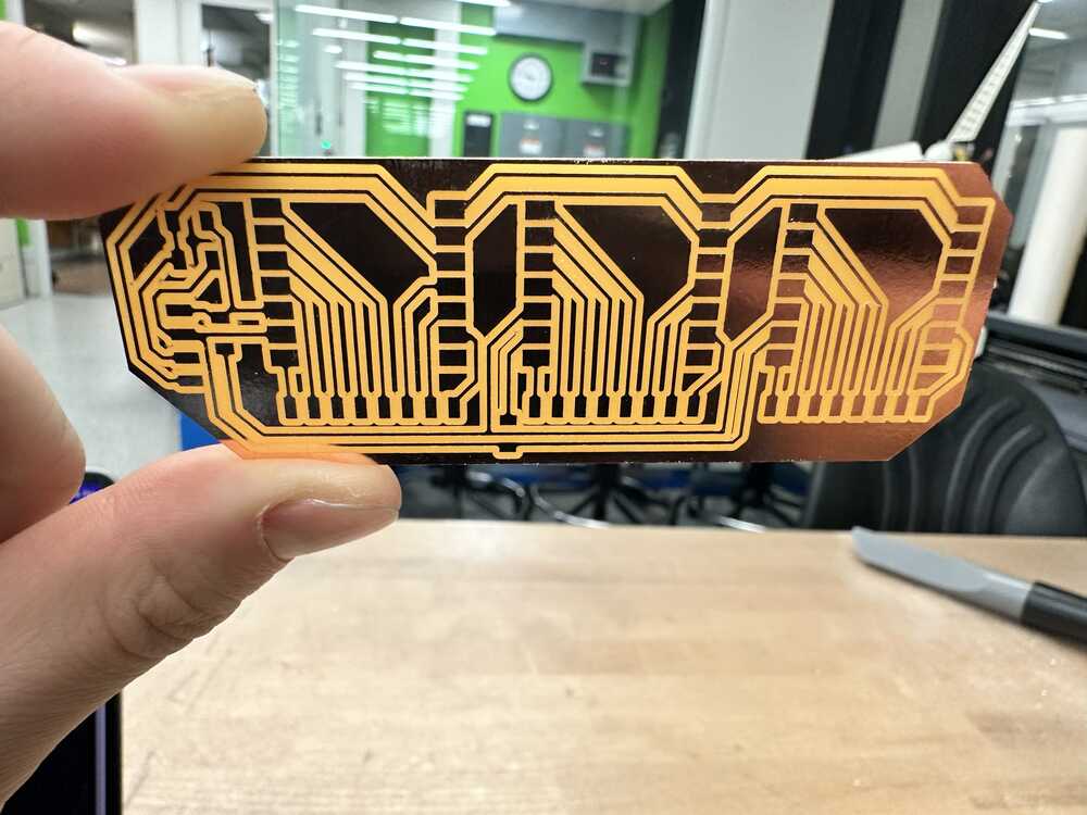
After milling, the board looked as follows:
Then I added the resistors and headers to the board:
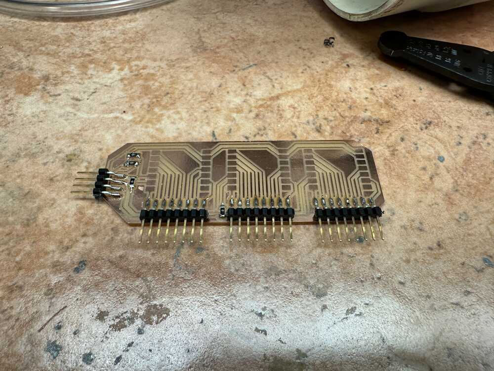
And finished stuffing the board by adding the three Xiao ESP32S3 boards:
Testing I2C
To test that I designed the board correctly, I programmed the leftmost board to serve as an I2C controller, and look for devices that are connected to its I2C bus. As it was the only board that I programmed at this point, it naturally did not detect any devices:
The built in Arduino library, <Wire.h> talks to the hardware I2C on the board to abstract most of the I2C protocol specifics away, and makes the API for using I2C quite simple.
For this, I slightly modified the scanner code from this website and uploaded it to the first Xiao.
Afterwards, I programmed the second Xiao to initialize itself as an I2C peripheral, and have address 20 (0x14).
Finally, I programmed the third Xiao to be an I2C peripheral with adddress 21 (0x15).
Sending data over I2C
The next thing that I wanted to confirm was to send data over I2C, instead of just doing the I2C handshake (calling Wire.begin())
In my final project, I will be having these three boards take in sensor data, and send it over I2C to the controller. I don’t have the controller ready, so I used one of the boards as a temporary controller board.
I had the first board act as the controller, and request data from the two peripherals over the I2C line. The peripherals respond by sending either “20msg” or “21msg” as their response to the request from the controller.
Here is what it looks like in action.
Wireless Connection
I2C can have many many devices on the same line. And, Arduino is best used for the step response, since it is a lot more efficient than MicroPython, while making a web server and controlling an I2C screen is easiest in Micropython. Thus, to make my UI, I decided that I would employ another board that is connected to the I2C lines, which will receive the sensor information from the three boards, and output the data over WiFi and on the display.
To test functionality, I simply recreated Neil’s MicroPython web server example that can be found at: Web Blink Example
And here is his video:
I will plan to make my own web app next week (spoiler: will feature websockets) which will be hosted in a similar way to Neil’s blink web app.