Assignments
The individual assignments for this week are:
- write an application that interfaces a user with an input &/or output device that you made
Making a web app
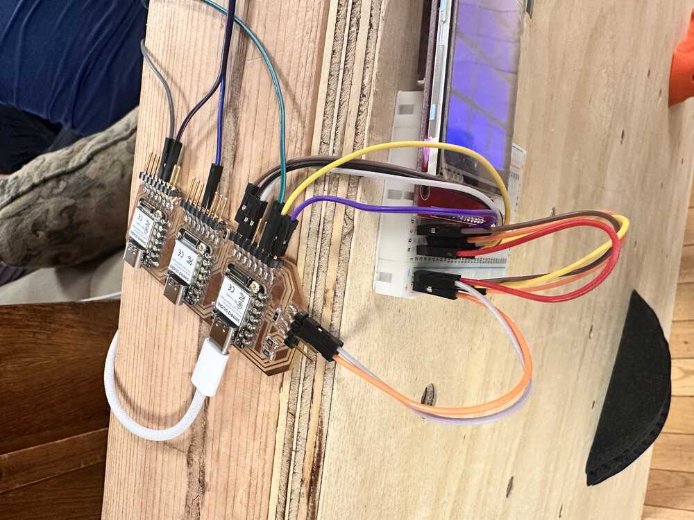
One of the biggest challenges this week was deciding whether to use MicroPython or Arduino. Last week I designed and printed a board that has three Xiao ESP32S3’s on it, which are connected via I2C. I was planning to only use these three boards, and have one of them serve as the “leader”, which would collect step response data from its seven sensors, AND be responsible for collecting the sensor data from the others, AND host a webserver that could talk to my phone, AND control a LCD screen.
I originally leaned towards having the leader board’s code be written in MicroPython, while the other boards run the step response script that I used in a previous week.
Anthony told me that to get best results, I should use Arduino with the step response sensors since Arduino is a lot faster and more consistent. Moreover, even though Neil used MicroPython in his web app example, there are sufficient libraries in Arduino to do everything that MicroPython can do.
This is quite a complex solution, and would probably require all of the boards to figure out synchronization with each other.
I have since realized that there is a much simpler solution: I move the “leader” functionality off of one of these three boards, and have these three boards act exclusively as sensors and sensor output boards. I then program another board that is connected to these three boards over the same I2C connection, and have that one be responsible for collecting the sensor data from the three sensor microcontrollers, host a webserver, and control a LCD screen. Moreover, this board’s software can be written in MicroPython, since it isn’t as sensitive to fluctuations at runtime. Additionally, this modularizes the code, as I can program the sensor boards once, and once I am confident that they are behaving correctly, I won’t need to conftinue to modify their code anymore and run the risk of messing it up.
Thus, this week I will be focused on writing the code for the “leader” board, which will be responsible for hosting a WiFi network and web app, receiving sensor data, and controlling a LCD screen. Since this week’s assignment is focused on writing a UI, I’ll be focused on the first responsibility.
Also, in the process of deciding, I found a few guides online on how to make quite advanced projects on an ESP32, including hosting a React app, which I am surprised fits on an ESP32’s flash. I would like to try them out at some point, maybe in the future when I have more time. But for now, I’ll just list them here.
Making a web app
I used Neil’s blink example as starter code for this project.
The important things are: to modify the HTML and JS in the server response so that I have the UI I want, have the device keep some sort of state to represent the current sensor data, and handle creating and accepting websockets with the client device (phone or computer) over WiFi.
If I have time, I also want to figure out how to have it store data in the flash, e.g. a leaderboard. A quick search shows that I want to be storing this data in EEPROM.
Websockets
I found a website that I think could be very useful as a guide in implementing websockets.
Final Project UI
Ultimately, I decided that the best way to go about displaying the information for my final project would be to have a LCD or LED screen mounted somewhere on the climbing wall.
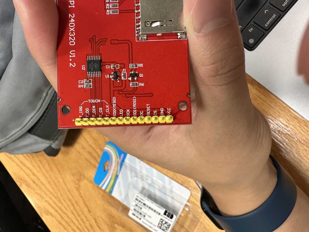
The model of the screen that I got from Anthony was actually a SPI screen, so I ended up using some of the broken out pins from one of the three boards to talk to the screen.
The model of ther screen was “TFT LCD 2.8″ 240×320 RGB SPI Display with Touchscreen”. I didn’t actually need the touchscreen feature, although it could be used in a future iteration of the project.
I used this website as a guide on connecting the wires to the display, as well as using the starter Arduino code to actually connect to and control the display.
The bottom of the screen looks like the following:
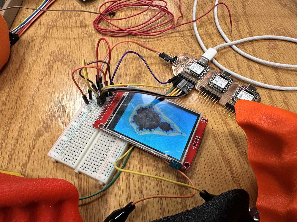
I know that Neil hates breadboards, but I thought that the most time efficient way of dealing with those pesky pins on the display was to just attach it to a breadboard. I was having issues with getting the display to interface properly with my microcontroller, but after trying multiple configurations of the wiring using jumper cables recommended in the guide, I eventually was able to get the display working.
The example code in the guide generates a screen with the mandelbrot fractal which looks like the following:
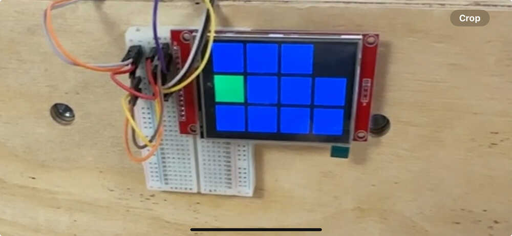
I devised a simple UI consisting of a few squares corresponding to holds on the wall, which would be blue by default, and turn green when their corresponding hold was in use.
I used ChatGPT to help me write the portion of the code that would draw the squares on the screen. (i.e. the for loops and the simple and tedious arithmetic for generating the boxes in the right places). This was the only portion of the code that was written by AI.
This is a still of what the UI looked like in action. (note there are only three boxes in the top row because the first ESP32S3 only had three pins available for touch sensing after SPI and I2C were accounted for).