Assignments
This week, we only have a group assignment for the entire section
- design a machine that includes mechanism+actuation+automation+application
- build the mechanical parts and operate it manually
- document the group project and your individual contribution
Nerf gun
For our machine, we decided to make a self actuating nerf dart launcher that uses computer vision to aim at people and launch darts at them. The purpose of the machine is to assist Neil in his tirades against people entering class late. The imagined use case was to set up the machine pointing at the entrance to the classroom, and turn it on after 1:05 as a fun punishment for those who arrive late. As an additional feature, it will say Neil’s signature “Please don’t dribble in” as it shoots.
Team organization
With the idea decided, we met on Thursday to discuss modularizing the project so that we can break into smaller teams and work independently in parallel.
We split the work into four teams with the responsibilities as follows:
- Launcher team
- Essentially, design and make the flywheels that accelerates the dart.
- Actuator team
- Design and make a hopper system to serve as a magazine for darts, and the actuator to send a dart to the launcher.
- Software/controls team
- Write program logic to aim the launcher and decide when to fire a dart.
- Structure team
- Design and build the base, motors, and platform for the other teams to interface with.
Individual Contribution
I was on the structure team. My specific responsibility was to design and build the base, and to include the motor that would control the yaw (aiming left and right).
In the planning drawing below, I was “person 2”.
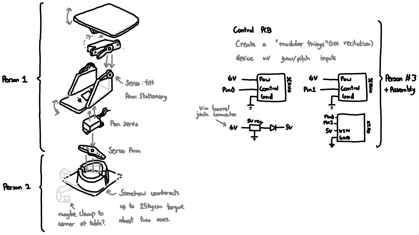
As part of our kit, we were given a couple of DS3225 standard size servo motors. There were a few different servo horns included in the kit.
After measuring the different included horns with calipers uncuccessfully, I found that the easiest one to measure was the plus-shaped one, as I could easily measure the diagonal length of the plus (or the x shape in this case), and 3D print out a box around it so that it would fit in almost perfectly. I also measured how far the holes in the arm were so that I could make screw holes in the base as well. This took a lot of painstaking work using the calipers to measure the distance to the screw holes from the servo axis.
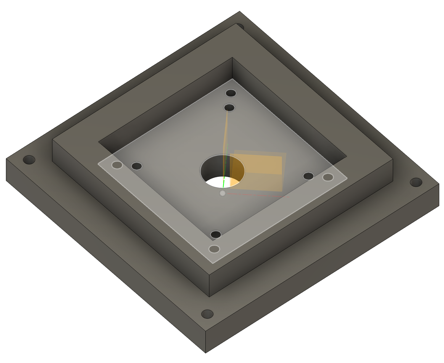
To attach to the base, I decided to design a small 3D printed piece that connects the whole structure and fits inside a larger base made out of acrylic, to save both printing material and time.
I created a piece that had an extrusion around the servo horn, as well as holes on the base aligned to the holes on the servo horn which could receive the screws that came with the servo kit.
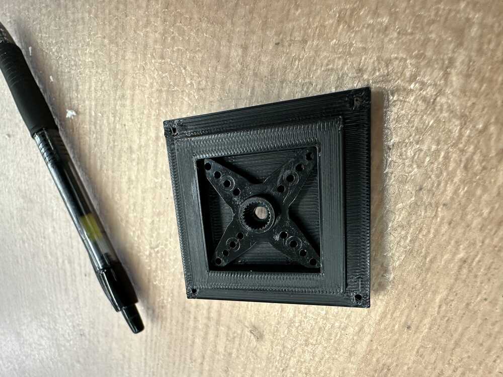
This is what my first iteration looked like:
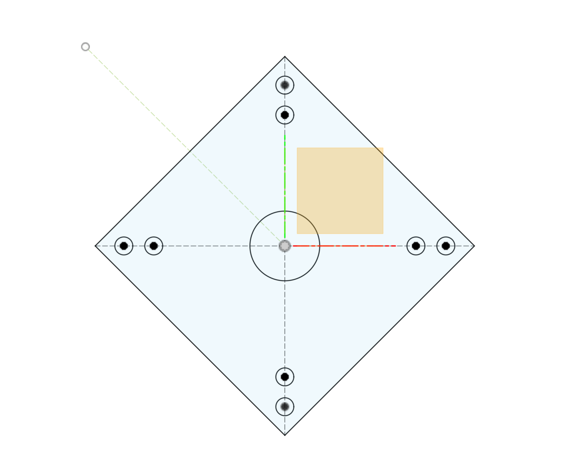 Shows the screw holes on the bottom of the base, including the central hole for the large screw attaching the horn to the motor’s shaft.
The servo horn actually fit perfectly inside the box, and was held inside quite securely with just friction. However, the main issue with this first iteration was that the walls of the box were too high, which meant that the servo drive shaft couldn’t fit all the way in. Also not shown, but some of the holes that I added in the bottom weren’t perfectly aligned.
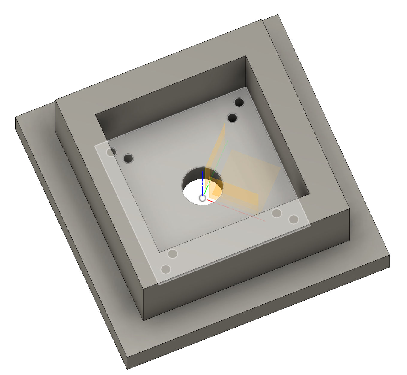
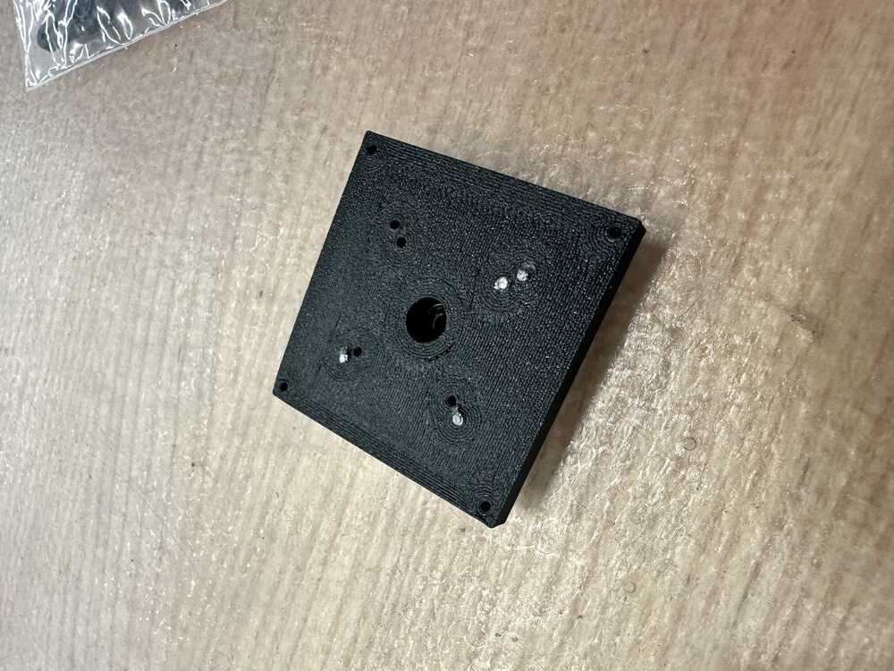
On my second iteration, I lowered the height, and began adding the screws to hold the horn to the base.
It looked like:
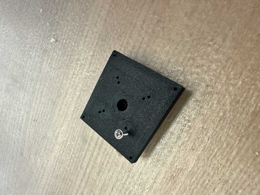
Unfortunately the screws that came with the kit were of very low quality, and they all ended up snapping when I tried screwing them into the holes and into the corresponding holes in the horn. However, they only snapped after they had already connected the base to the servo horn.
Next, I was able to attach it to the rest of the structure, which looked like the following:
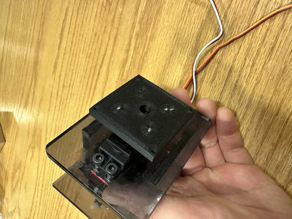
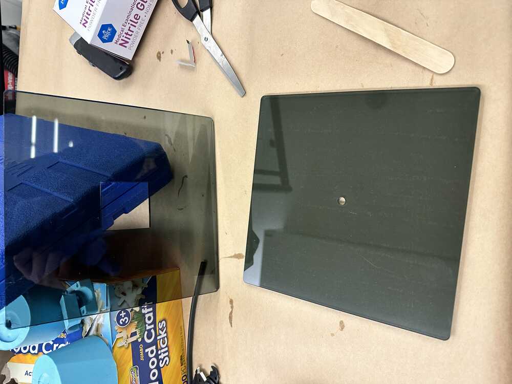
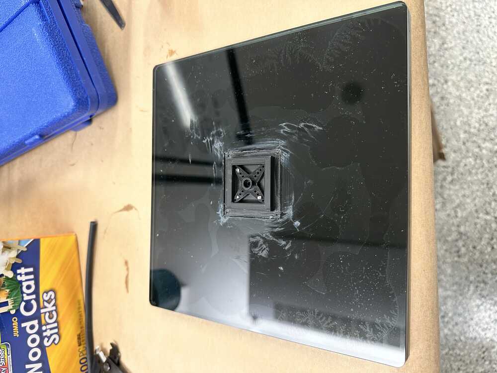
Now I created the rest of the base by laser cutting out two pieces of acrylic, which would be sandwiched on top of each other, with the top piece having a cutout for the 3D printed base.
I attached the two pieces with glue, and then glued the base piece I designed to the cutout on the top piece so that it was now all connected securely. I also included a hole at the bottom of the base, through which we could fasten the screw which held the servo horn to the servo motor.
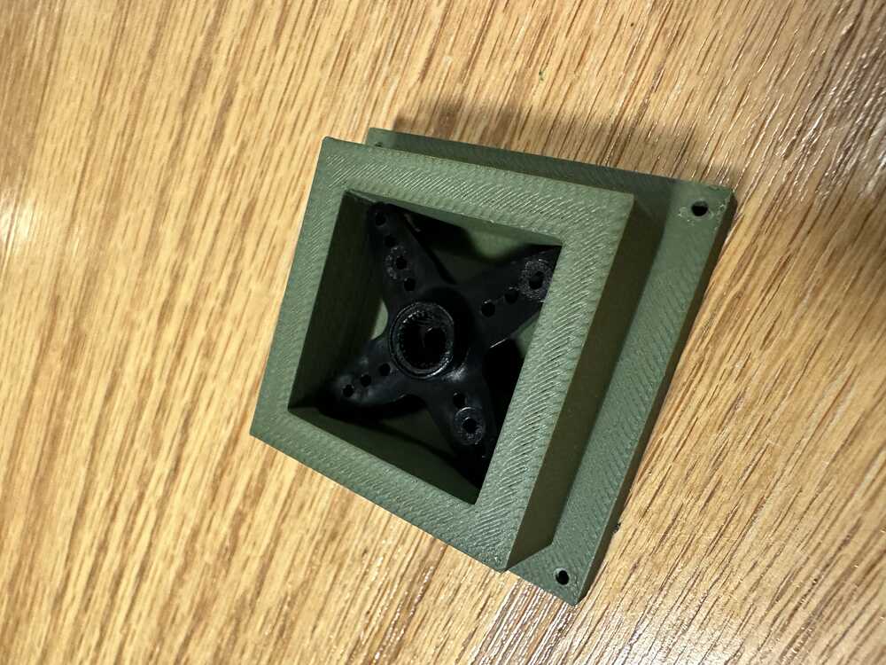
The final construction with the 3D printed and acrylic bases attached looked like:
Group Contribution
My part fit into the rest of the group project, which is highlighted here: Group website