Week 4 - PCB Design
# Goal
For this week, I wanted to translate the breadboarding I did for the embedded programming week into a PCB and give the circuit its own standalone battery. The goal is to see if an IMU position/velocity tracker can be compact, lightweight, and accurate enough to insert into a pitchable ball for internal tracking. If this goes well, I will try and incorporate a more refined version into my final project.
# PCB Design
For the design, I chose to use Eagle because so far I’ve been sticking to the Fusion360 workflow. I started by downloading the fab library in Eagle and inserting all my parts. I had a discussion with Anthony about picking a lightweight battery and IMU options. The ESP32-C3 has a battery hookup on the back and supports battery charging, so we considered one of the small LiPo cell batteries, but ultimately decided that it probably wouldn’t be able to get enough amperage across for WiFi usage. Instead, we settled on using two or three AA batteries. Anthony couldn’t find the 9-axis IMU I wanted to try, so I stuck with the MPU6050 for this week, which was fine since this turned out to be a pretty crude first go at the whole PCB design + fabrication process.
I used a 2x2 header pin block for the batteries and routed that through a diode and into the 5V input to the ESP32-C3 for power. The MPU was pretty straightforward – the footprint didn’t exist in the fab library but I just used a 1x8 through-hole scheme and I plan on attaching the MPU to the backside of the PCB (upside-down). Finally, I added a switch to give myself room to code more flexibly on the software side of things.
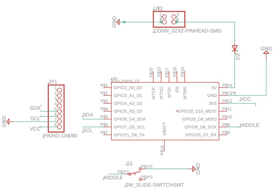
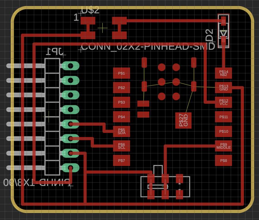
I ran the ERC which came out nicely and proceeded to the PCB wire routing.
This was also mostly straightforward; although, everything took lots of time since I’m new to PCB design. I imported the fab DRC rules and routed with 20 mil width. For the board outline, I made it as small of a rectangle as possible and then rounded the corners. Some takeaways:
- The ESP32 footprint had lines internally that wanted me to connect to ground. That’s all done internally, and doesn’t need to be routed on the PCB, even though the DRC will yell at you for not doing so.
- Put the microprocessor at the edge of the board, with the USB port facing out. I didn’t do this, but it was fine this time around because the USB-C connector is really flat. In general, it’s good practice to put it at the edge of the board.
- Double check the orientation of everything before you start wiring! I almost gave myself a heart attack after finishing the routing because I thought I had flipped the ESP32-C3 footprint. I didn’t, but I learned that double-checking orientation is a good idea before routing.
# Files
Coming soon!