Week 6 - Molding and Casting
# Goal
My initial idea for this week was to attempt to cast a wheel for my final project. However, the materials we had in the shop (OOMOO, epoxy, and drystone) weren’t ideal and any material I could order (rubber) would not come in time for the week. Also, the wheel would need to be casted around an axle, but I haven’t figured out my motors for the project yet. So I decided to wait on this until I have the motors settled.
For my other idea, I wanted to tinker with the possibility of casting a ball for my final project. Specifically, a ball that would have a funky trajectory when thrown, so even a simple prototype of a pitching machine or a pitching machine driven by one wheel could be fed this ball and still throw “breaking” pitches. I floated several ideas by Anthony and we ended up settling on casting a sphere around an internally moving mass. I ended up using a steel ball bearing that was free to rotate within a torus. The mold will simply be a sphere, which means I can also print solid finger holes or seams that will turn into indented features on the casted ball, if I want to try out more traditional methods of making a ball that can curve.
# Milling the Wax Mold
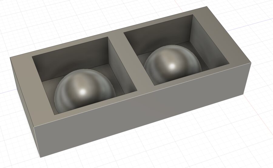
I started by creating a sphere in Fusion and then slicing it in half and adding it to a model of the wax mold:
I then designed the CAM following the instructions from recitation in Fusion’s Manufacturing mode and Anthony helped me with choosing the right finishing tools for the job. The final process was:
- 1/4" flat end mill up cutter 3D adaptive cut (rough cut of sphere)
- 1/4" flat end mill pocket cut (remove remaining wax missed by first cut close to the walls)
- 1/4" flat end mill spiral cut (finishing the upper half of each hemisphere)
- 1/4" flat end mill 3D contour (finishing the lower half of each hemisphere)
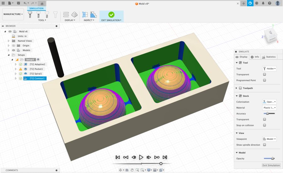
We tinkered with the stepover parameter for the finishing passes to optimize the detail of the sphere while keeping the length of the milling to ~30 minutes. The simulation feature is pretty helpful for seeing how the cut will turn out:
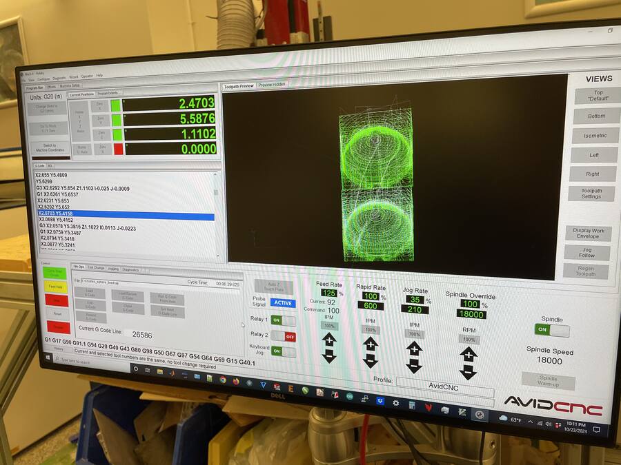
When everything looked good to go, we converted the toolpaths to GCode and sent it to the mill. In the preview we discovered a couple errors with the CAD; (1) the mold was rotated 90 degrees from the jig we had for mounting to the router table and (2) I had done the CAM zeroing to the top of the mold, but we had zeroed the machine at the bottom. These were easy fixes and then the CAM was ready to go.
I only used the 1/4” flat end mill, so we didn’t need to swap the tool during the routing, which was nice.
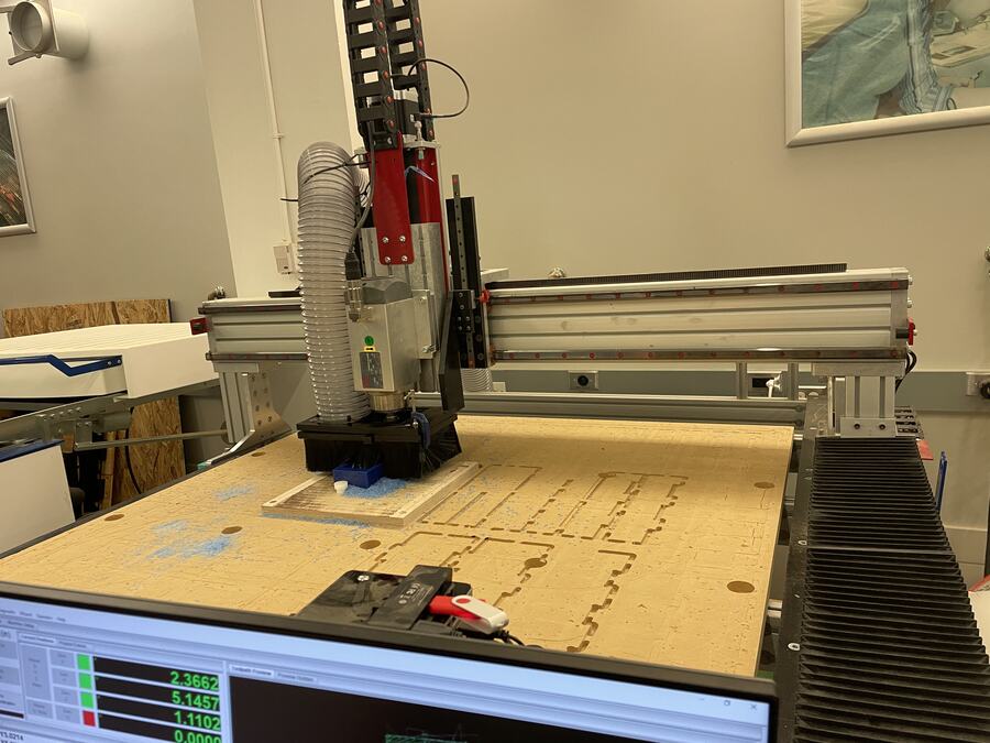
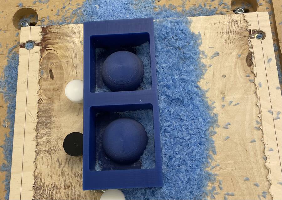
Here’s the milled wax mold:
# Pouring the OOMOO Mold
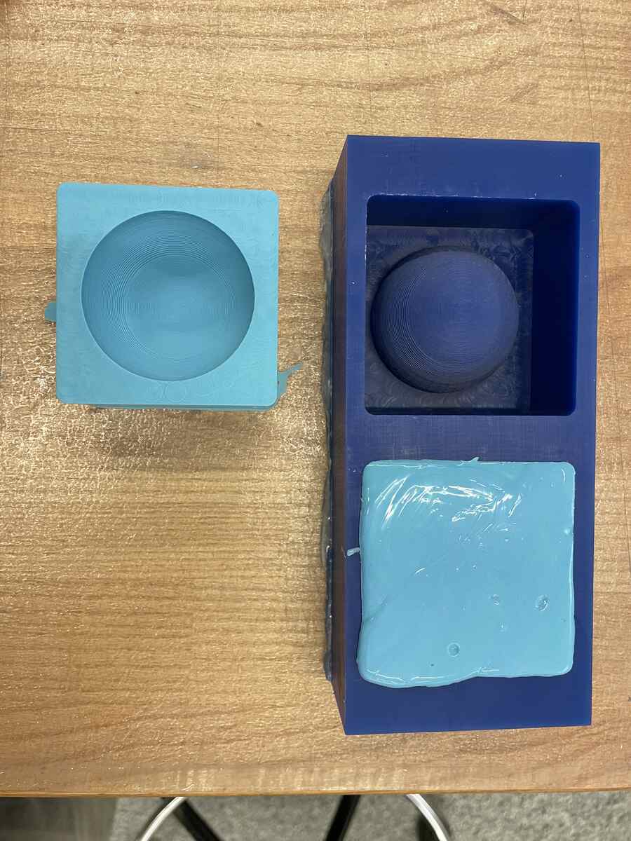
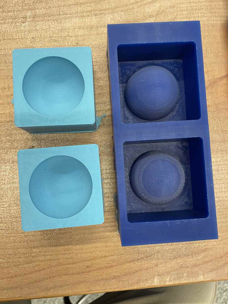
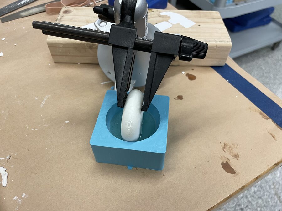
The OOMOO process was relatively straightforward. I mixed the two OOMOO liquids in the right proportion and then poured it into both halves of the mold slowly, as to reduce air bubbles.
 |
 |
# Printing the Torus
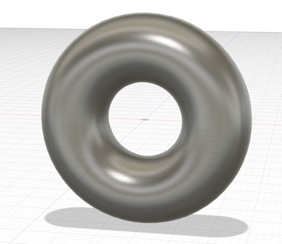
I swung by Edgerton and picked up a steel ball for my rotating mass. In Fusion, I can directly insert a torus as a solid body, so the CAD was a simple plug-and-play.
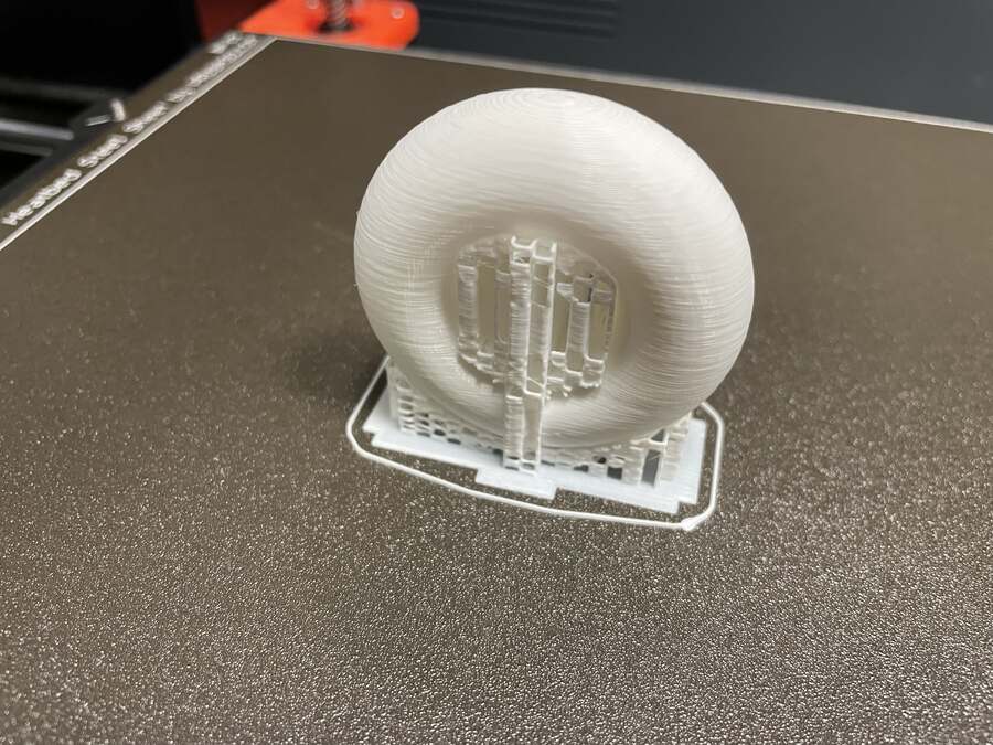
And we’re printing…! I stuck around for the first third of the print so I could pop the ball in. You can see kind of see it in the image I took right after.
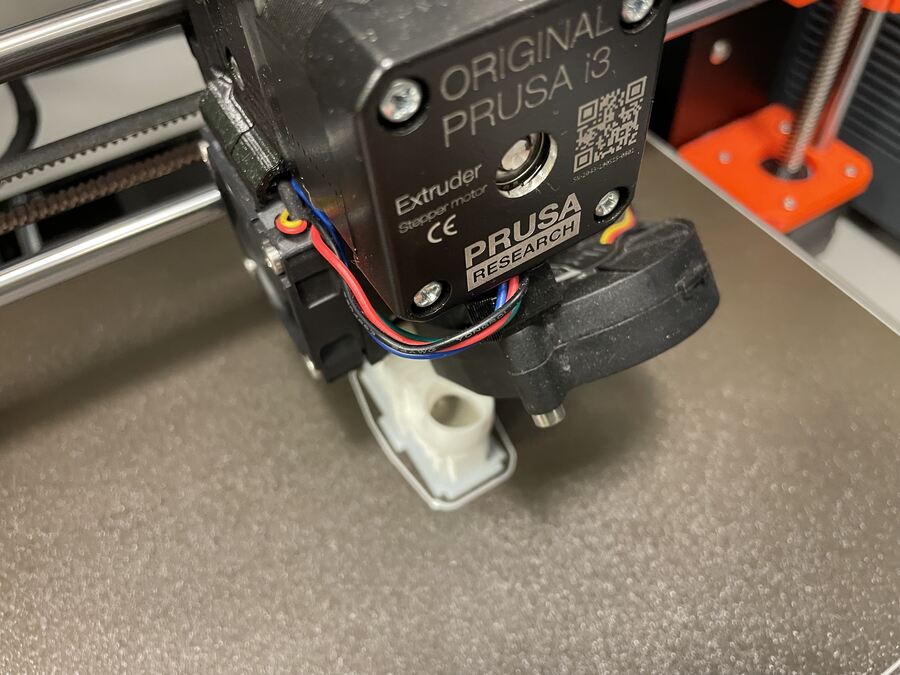
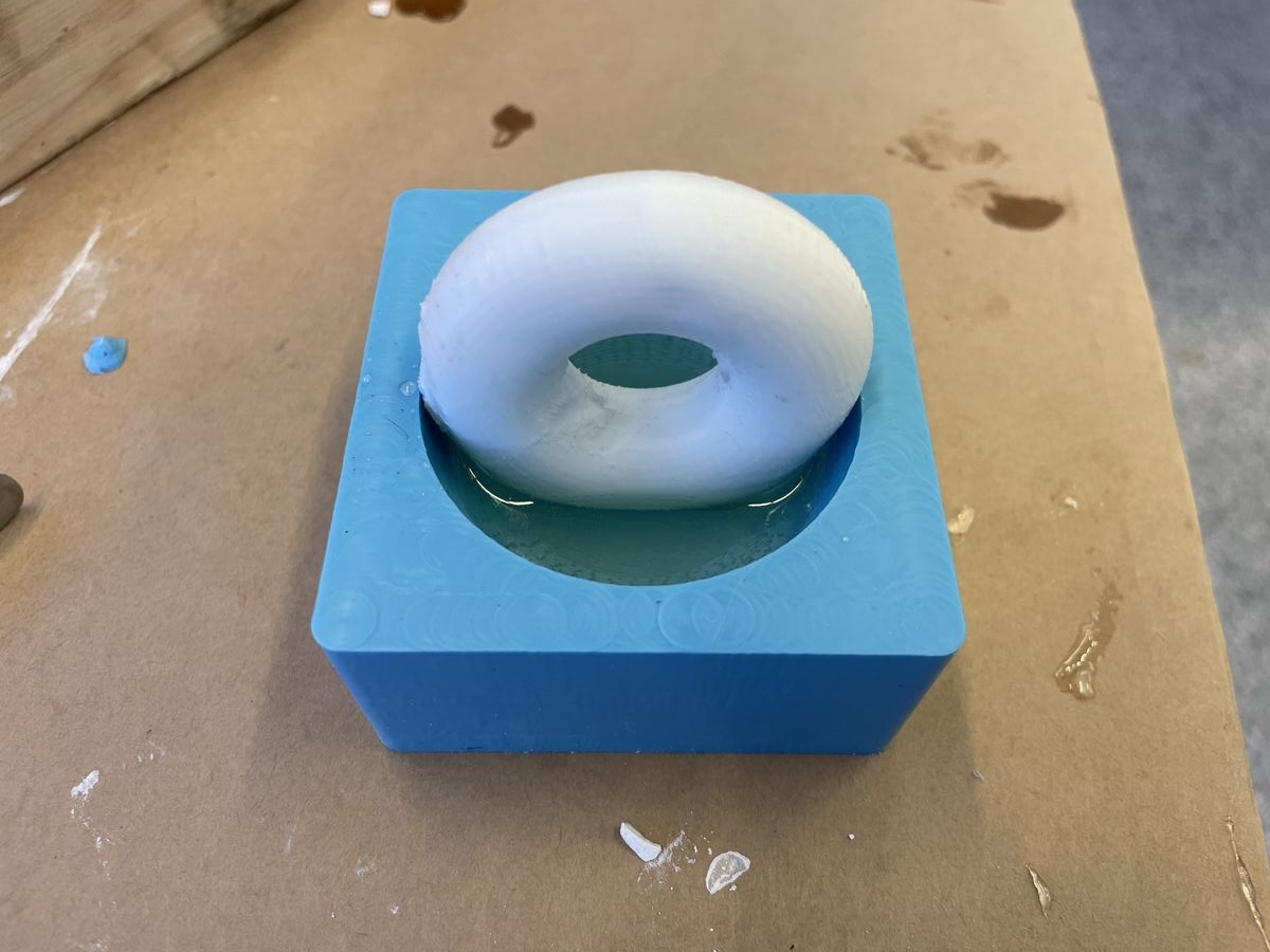
Here’s the printed torus with the ball inside:
 |
 |
# Casting in Epoxy
Casting the ball in epoxy was quite the journey. The plan was to do it in two steps. First, pour just enough to hold the torus in place. Then, pour the rest of the ball. The epoxy process was similar to the OOMOO (mix and combine in a specific ratio), but with the added step of using a vacuum pump to pull out air bubbles before pouring. The first step went fine:
 |
 |
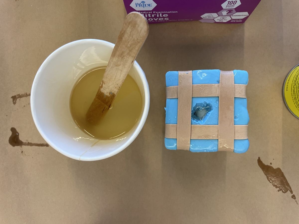
However, the second step actually took me three pours. To start, I poked a hole in the top half of the mold. I centered the hole, which then fit right over the torus. This was a mistake, so I had to widen the hole until part of it could funnel the epoxy into the inside of the mold. For my first attempt, I poured the epoxy until the hole at the top welled up. When I came back to check on my cast after it had hardened, I still hadn’t even filled past the halfway point. Unfortunately, it turns out I had barely added any epoxy to the inside of the sphere. Instead,a thicker part of the epoxy had just welled up in the hole leading me to believe the pour was done.
The second try, I poured slowly and massaged the mold throughout my pour to continually drain the well of epoxy in the hole at the top. Eventually the epoxy ceased to flow downwards, so I figured the pour was done. Wrong! This time when I came back to check the results, the sphere was almost finished. But in the top half, the side of the torus under the hole was filled, but the opposite side wasn’t. The epoxy had flowed through the center of the torus to fill the opposite side until the pressure was too high.
Finally, on my third try, I placed the hole over the last unfilled bit and made sure I drained into the mold until it was full.
# Files
Coming soon!