DECISIONMAKER 9000
Mechanical Engineering
The base of this pyramid for machine building week was the MechE team :) that worked tirelessly to rapidly assemble the machine in order to unblock all the other teams.
The XYZ Drawing
The MechE team concentrated on getting the basic machine assembled in the spirit of sprial development. First up was figuring out a single axis of 1 DoF to find out what motion parts we were going to need:
In order to get the basic machine built we put 5/6 FDM printers to work since no one was using them after hours. Kyle and Jonny focused on getting the xyz built. We decided to go with a simple cartesian design with one dedicated motor for x and another y. For the Z axis we used the micro servo to control the height of the pen. This was a kind gesture to our software and ee teams to avoid complexities. Our Z was modeled after the hackclub blot ("https://github.com/hackclub/blot"). Kyle built the XY while Jonny focused on the Z. We modeled, cut, 3d printed, and then assembled the drawing machine and was ready for bringup on saturday morning.
The Coin-Flippinator
For the coin-tossing component of the machine, we knew that we wanted to work with a solenoid to yeet (drive) a coin upwards, flipping it multiple times for true randomness. We needed something for the coin to sit in and reliably fall back into a flippable position. So Cyrus and Shun-Ying worked on a suitable design: a cone that could be fitted to the machine and also house the solenoid conveniently in one piece.
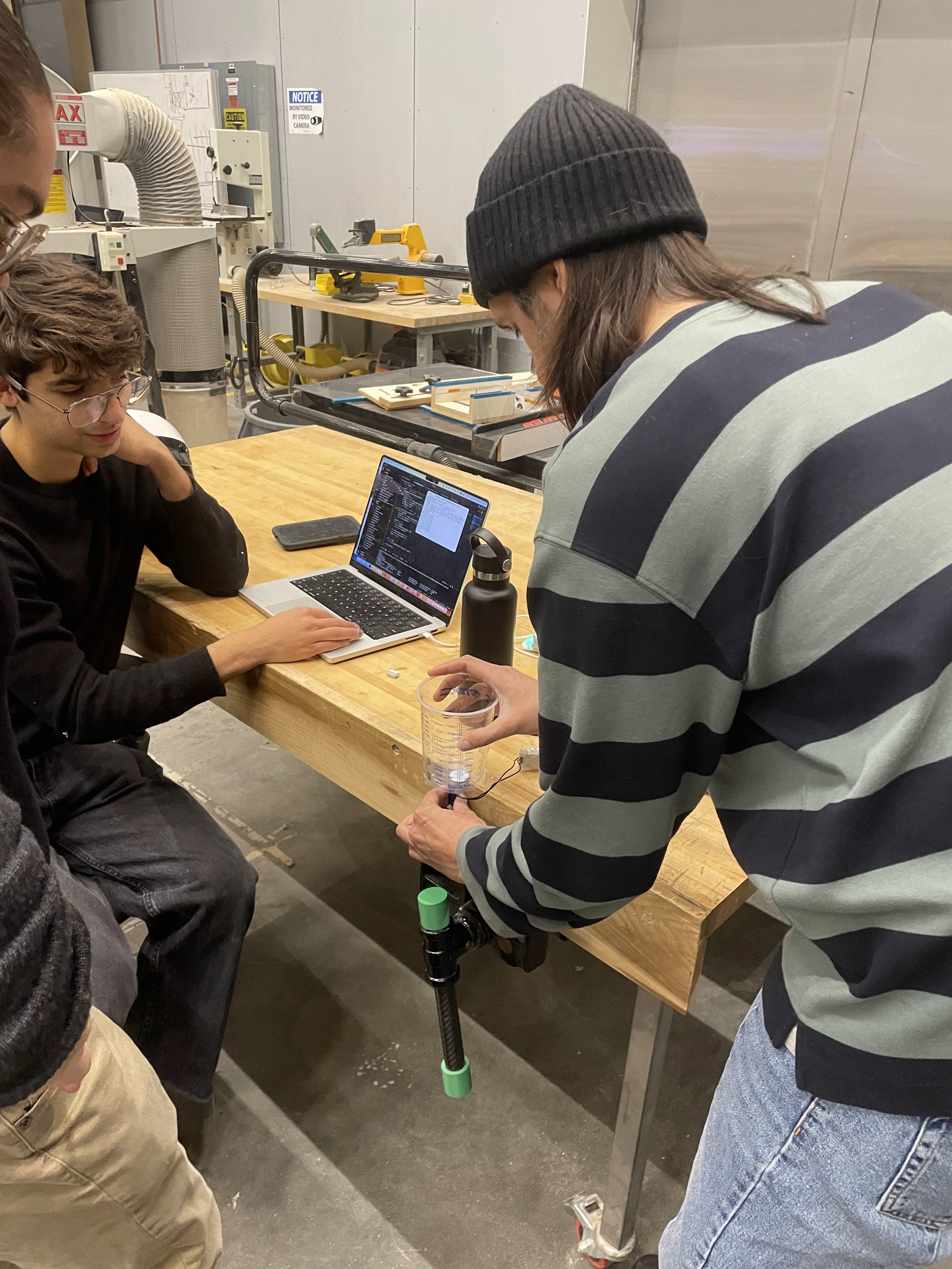
Coin Engineering
The coin went through several iterations from Kye, Jessica and others all took part in designing coins of different thicknesses, layers, colors and diameters. We studied the different yeet'ability of the coins and landed on an optimized design of 30mm dia and 1mm thick.
Components used
- 1 inch stock
- 3 inch stock
- Pully bracket
- 4 x carriage assemblies (3 x wheels, 3 x M5s, 1 x printed carriage)
- 2 x Stepper asm (motors, driver board, belt sprocket,motor mount, 2 x M5s)
- 2 x Belts
- 2 x Belt clamps
- 2 x Tensioners (sproket, 3d printed mount 3 x M5)
- 18 x T-slot Nuts M5
- 6 x T-Slot Nuts M3
- Z Servo
- Pen holder and 2x M5s for clamp
- Pen track
- 16 x L-Brackets
- Acyrlic base
- 4 x paper fixtures
- Wire harness
- FET PCB
- H-Bridge
- External Power Supply
- Router
- 4 x Flat cables + Connectors
- Streaming Camera
- Coin Camera
- COIN
Electrical Engineering
The EE team was comprised of a number of wayward souls with a variety of backgrounds and experience levels. Many of our number were, rather than EE hardcore experts, merely those who sought to get better. For this reason, there was a bit of a learning curve / asking Jake and Quentin for their amazing help at times. The first step was making things move (with the TAs present so we didn't blow anything up). In the beginning, we were unsure of how much raw EE would need to be done in terms of pcb design, soldering, etc etc. Jake got us setup with his components, which included four motors, a hbridge, a solenoid, a servo, and more. We also got a kit for making ribbon cables of various lengths and a router for coordinating all these parts. After a bit of trial and error with setup (setting up a virtual environment, installing dependencies), we ran the test which imported a svg and "drew it" with the motors. The next step was to get each component moving, since we would need two motors, a servo, and a solenoid for our project. We floundered about for a little before we realized we could simply use Jake's hbridge test program. After we made each piece move to confirm we could, we then figured out how the coordinate system of the motors worked so we could actually control the motion to direct it anywhere we wanted. Some of the EE team were away over the weekend, so they speed ran getting our physical setup of the motors on a structure with the track and everything. This made it easy for us to start using the motors with our coordinate system. MechE had decided to use non-CoreXY since its a simpler coordinate system which met we just needed to figure out how to make each motor move in isolation. After some trial and error of determining how it moves, we determined the rough bounds of what our machine could fit, how many lines we could have, etc and how to reach every point in code. We discovered that the system that worked with the preexisting code we were given had no concept of "absolute position" - it moved relative to where it was set when the machine started, allowing negatives. This required us to define "machine origin" as one of the bottom corners where we would move by hand before each run. We then wrote some code to move to any xy and move "home", which was simply just a case of adding some globals and keeping track of where the machine was at any point. An issue we ran into at this point was the machine simply...not moving to where we told it to go - we would tell it to go positive X, and it would go negative, or move in a jerky fashion, or otherwise do erratic things. Quentin saved us here, telling us it was preferable to use the function goto_and_await instead of goto_via_queue - the second was causing weird issues where it wouldn't await properly, thus causing the motor to get out of sync or move in a jerky way. Now came time to integrate our code with the software/server side of things. Jessica and the rest of the software team made it easy to integrate the embedded code we wrote, so this was a relatively straightforward process. We then tried the full system and somewhat amazingly it worked (very nearly, we needed some more calibration). With this much unexpected success this early (Sunday night), we moved to the next spiral, which was getting the solenoid to yeet harder - in its original form it was quite weak and was only baby yeeting the coin due to a variety of current and voltage limitations of the connectors we were given. We tried some bigger solenoids, but they barely moved, likely because of their increased weight. Sophie then clutched and made a new board to support a stronger solenoid, which we made and then worked much better at yeeting the coin.
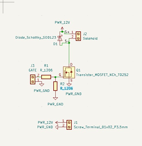
However, it was at this point we ran into a number of technical difficulties which caused a lot of tears and pain... Basically the source of our woes was that we needed longer cables so we just made some..or so we thought. It turned out that the cables we were making were crimped very badly, likely causing only power and not ground to be connected, or something similar. Therefore, we then killed a motor and very nearly killed the router. It took divine intervention from Quentin and Jake who swapped out the dead port to save us from our sins. (Thanks again wonderful TAs). We also had a number of issues after this with things not being plugged although they seemingly were, which we learned was caused by usb c actually having two different orientations which we did not know. The final issue that held us back was a final integration problem where apparently we were overloading the server due to not multi threading which caused weird problems. After the software team fixed that, we were good to go!
Software
The Algorithm
To review, algorithm works like this:
- the pen moves to the next line (or wraps back around to the top)
- the coin is flipped, and computer vision determines if it is red or blue, and uses that result to decide whether to strike the item or not.
- it continues until there is only one item left.
Quantifying bias in the algorithm
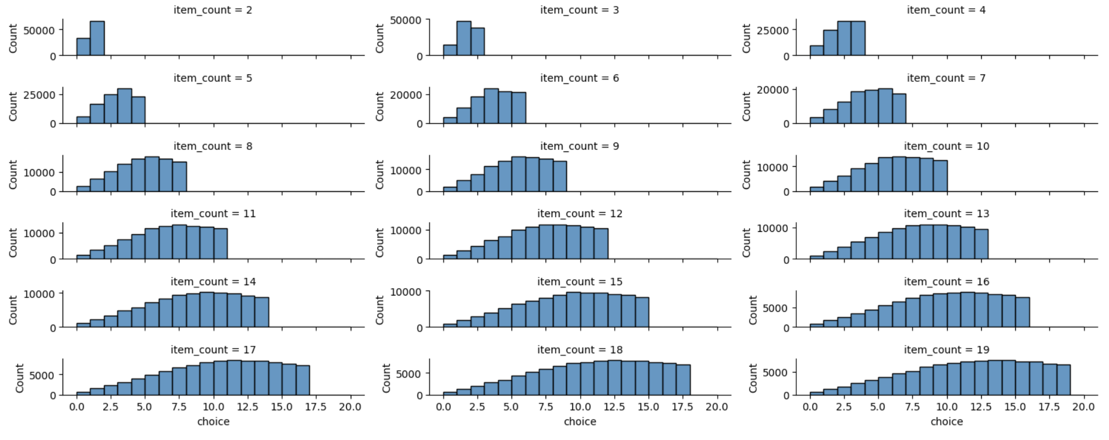
Even if the coin was totally fair, we suspected the algorithm was fundamentally biased: things lower in the list get a different number of coin flips than those at the top. But this can be hard to reason about and explain, so it's easier to just run a simulation. Here, we make 100,000 decisions with our biased algorithm, in cases where the number of decisions ranges from 2 to 20. We plot the histogram of how many of those decisions picked the choice at index i. If this was not biased by the decision index, it would be uniform. These are clearly not uniform!
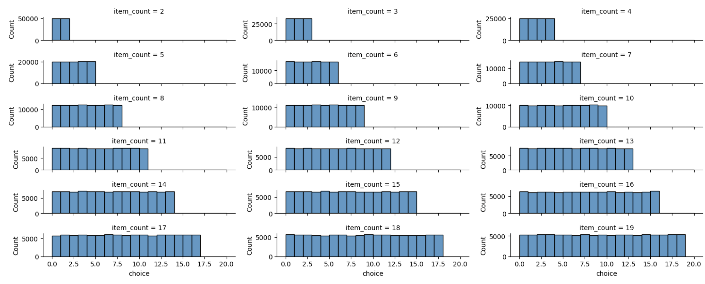
We also tested an alternate algorithm and showed that it was not biased. In this algorithm, we flip the coin ceil(log2(n)) times, and convert the result into a value between 0 and 2ceil(log2(n)). If the result is within the choices, we choose that one. If it's not, we reflip ceil(log2(n)) times.
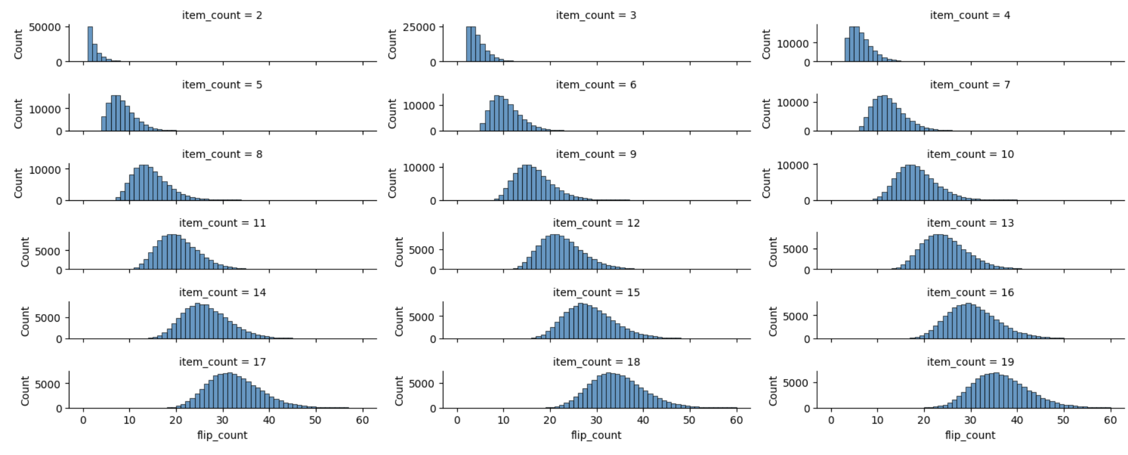
Quantifying very slow decisions
There's another concern with both algorithms: if you are exceedingly unlucky, you could end up flipping coins for a long time. We set an upperbound so the machine can give up on making a decision if it's flipped for MAX_COIN_FLIPS times.
Implementing the decisions
Ideally we'd be able to switch between the two algorithms. For this reason, the order of operations is made to work with both. start iterating:
- Check if we were told to strike through 0 or more items. This will be empty the first iteration. (since the more-fair algorithm strikes 0 or multiple items per coin flip.)
- Check if a decision has been made. If so, break.
- Finally flip a coin, process the result (deciding what will be striked through or if a decision was made), and go through the loop again.
- (jk, also double check if we've been asked to bail on this decision.)
Decision Making Service
The decision making service was written to be a central control. It initalizes the cameras and machine, and makes calls to the electrical engineering code and the computer vision code to execute the pieces needed for the algorithm. It also acts as a server that the UX can call, to either start a new game or to take a peek at what step the algorithm is at.
Configurations
We have a configuration file to adjust exact values, such as how many units are needed to reach the x and y coordinates of the first item of the list. (todo jessica, link to config file, and API) This made it trivial to fix it when the machine was striking lines slightly too high, or in the wrong direction. There are also command line configurations to choose which external services to rely on: camera or the machine. This made it possible to run the service without any physical pieces, with just the camera, with just the machine, or both. (these are required to be specified after an embarassing case of using the mock CV results and being confused why the CV algorithm was acting funny.)
Computer Vision
One aspect is identifying which color the coin is. We've made this easier on ourselves in a few ways: we create a blue and red coin by changing filament in the middle of a 3d print of the coin, we used a cone shape to funnel the coin to a specific location.The computer vision uses the Circle Hough Transform to locate a circle. Then it masks out the rest of the image, and measures the amount of red and blue. Depending on whether there is more red or blue, we classify the coin. Another way we made computer vision easier is by having the line-striking motion be completely based on the algorithm, and not use computer vision at all! The user needs to specify the number of choices, and then the computer will run through where those choices should be.
UX
There are three pages used for the UX: one that lets the user enter the number of decisions, one that shows an active decision, one for active decisions, and one after a decision is made. The active decision page shows the two camera feeds: one of for the coin flipper and paper with strikethroughs.