HTMAA 2024 - Week 6
Electronics Production
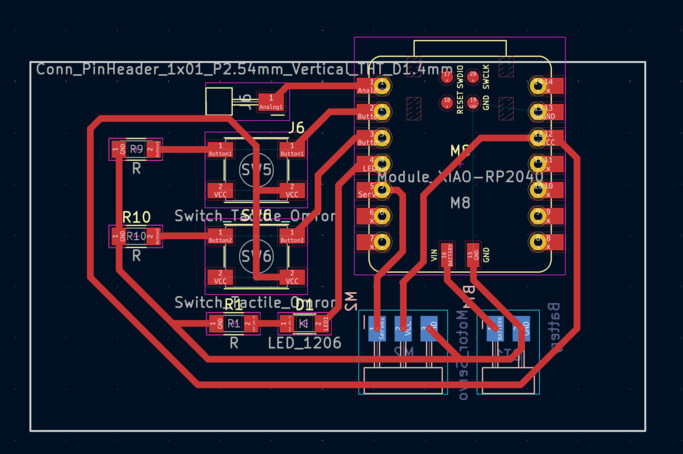
HomeThis week we were going to mill out the PCBs we designed. I had to do this weeks later because I was busy at the normal time that I would've been doing the assignments. Recall from last week what my PCB looked like!
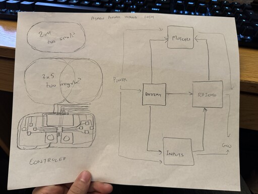
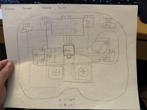
I decided to sketch out more notes about what I wanted my PCB to do originally as a controller, before eventually abandoning it again because it was just too large of a project for a weekly assignment.
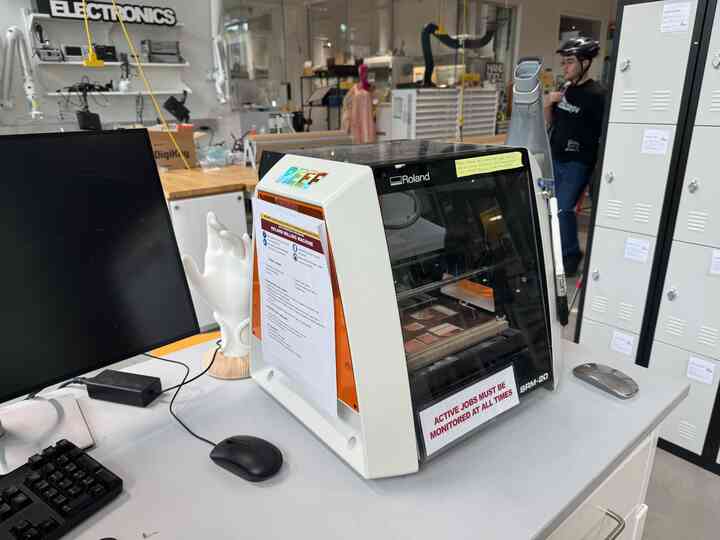
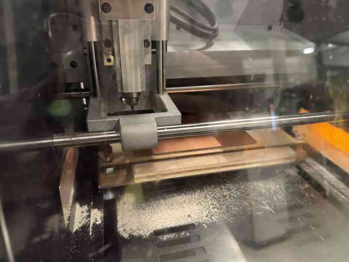
Here is the Roland SRM-20 mill in the REEF makerspace that we used to mill out our PCBs!
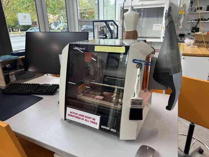
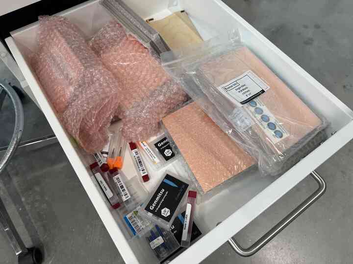
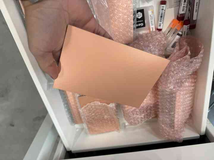
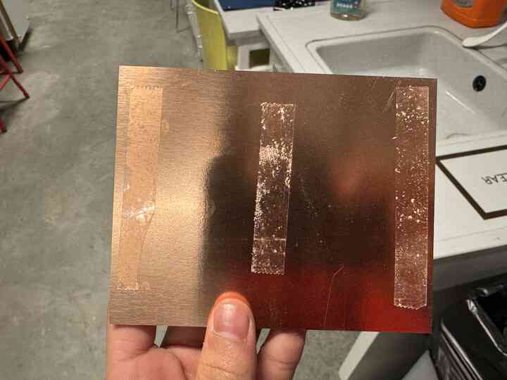
It had some copper boards for us to use to mill out the PCBs from.
I watched Leo as he taught Zihao how to use the machine. You have to connect your computer with Mods on it to the Roland, tape the board down using sticky tape, and calibrate the x, y, and z of the end mill, the x and y manually and the z using mods to help out.
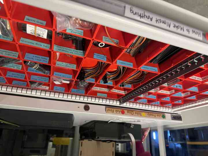
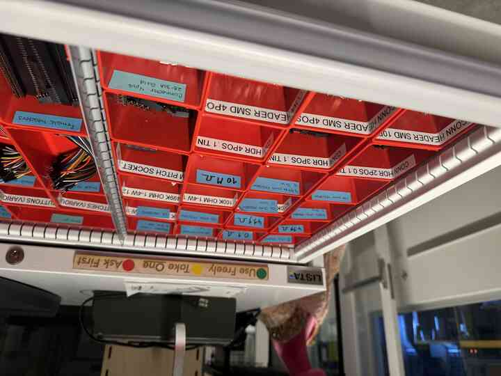
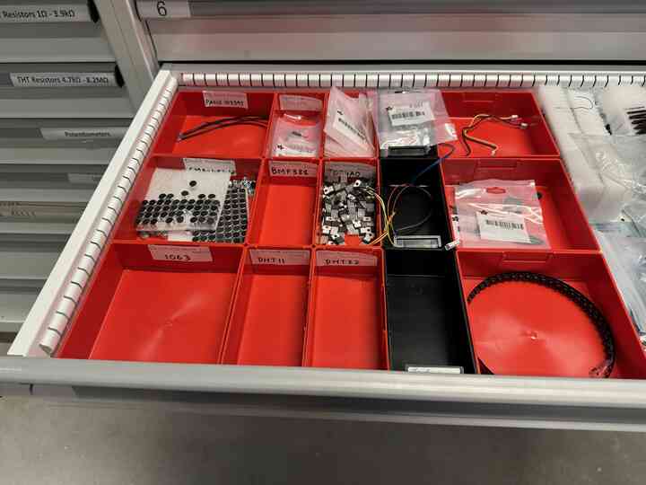
Here are some of the components that we had access to in the makerspace.
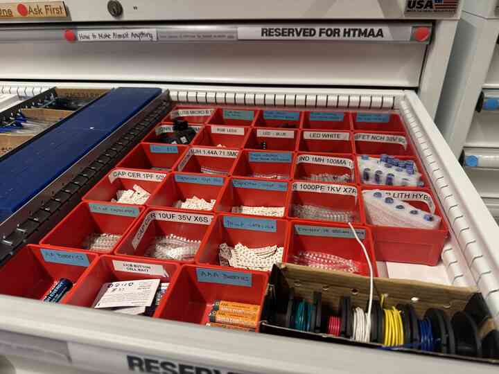
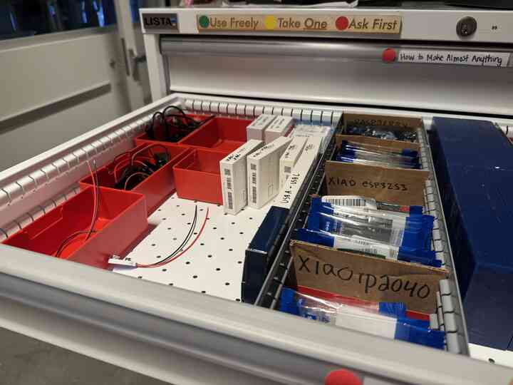
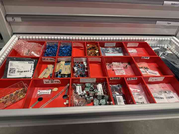
And here are some that we had in the EE lab!
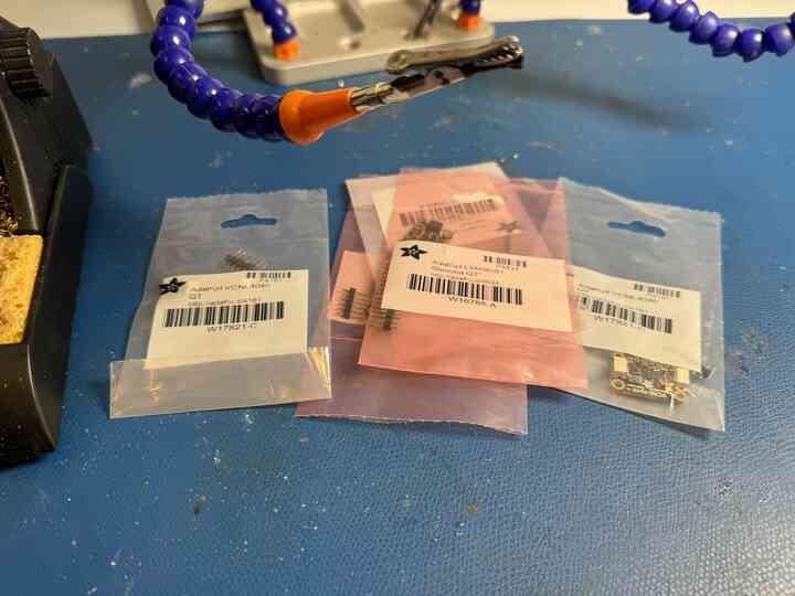
I took some of the components and soldered the header pins on them to practice my soldering.
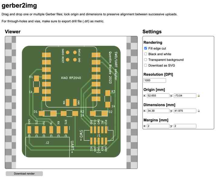
Anyway, back to the milling. Again, this is my PCB design.
I took the gerber file output and put it into gerber2img to get a png output for mods.
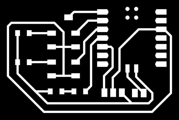
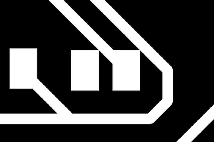
Here were the profiles of my PCB.

I put my png files into MODS and linked up my computer to the Roland after selecting the Roland as my machine.
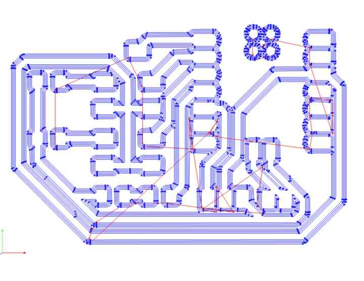
It traced out this path, which looked good to me.
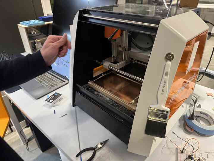
I calibrated the height of the spindle and then let the job run on the Roland.
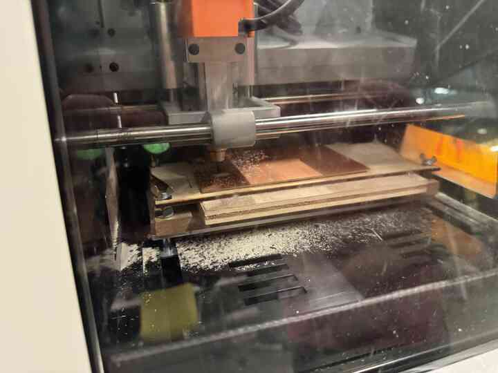
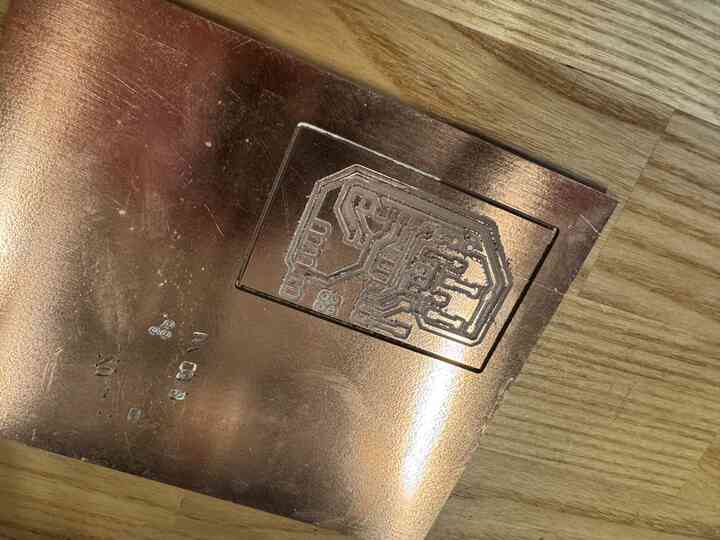
This is how it came out of the Roland!
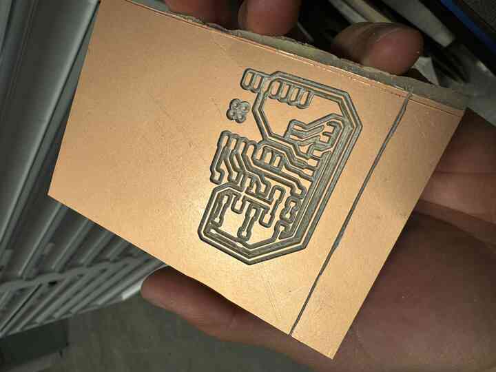
Originally I was going to trim the outside part of it, but I accidentally closed mods and couldn't remember the previous calibration coordinates, so Leo improvised and told me to use a Xacto knife to score and break the PCB.
Leo gave me a bit of a briefer on how to solder the super tiny components onto my PCB, somewhat breaking it in the process.
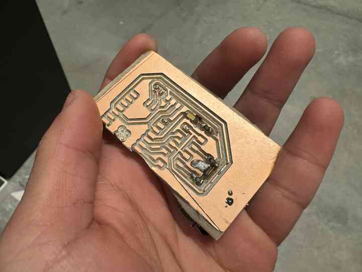
It's okay, however. I would have to remill my PCB anyway as if you look really closely at the trace diagram, ground is accidentally shorted to power at a trace that just barely overlapped with a pad.
And so I would remill my PCB. In the future, Leo recommended I use his project, Bitrunner, to mill out the PCBs because it was more straightforward and user friendly.
SO LETS DO IT.
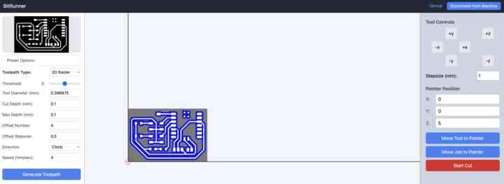
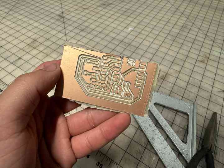
Alright let's load this up again, with a fixed trace.
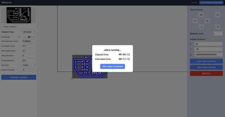
Okay looks great on time, only about half an hour!
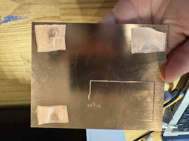
I put double sided tape on the bottom of the PCB, and fixed it to the board.
I realized I would need some more painters tape on the edge to reinforce the board adhesion.
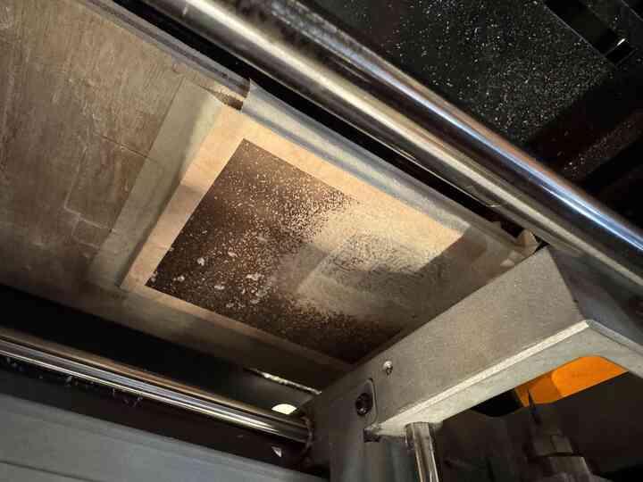
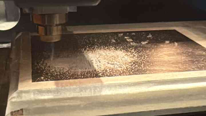
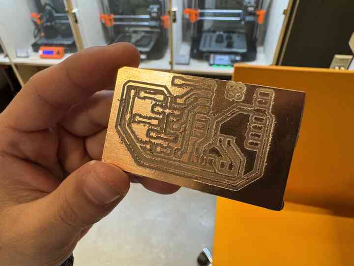
More milling!
Look at that profile!
It didn't fully penetrate through, I assume because the tape was thick and also could warp a bit leading to the surface being less level.
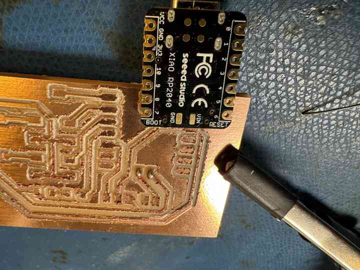
I just snapped the board out of its place and here it is!
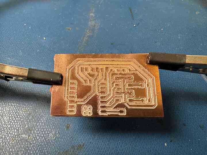
I put it in the helping hands to get it ready for soldering.
Here I realized there was absolutely no easy way for me to solder the battery traces on the bottom of the Xiao, so I just skipped them.
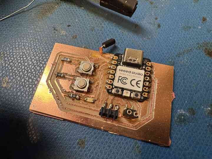
Here are all the components soldered! I did way better on soldering this time, although you can still see a ripped up trace for the analog input at the top.
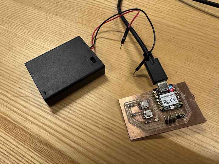
I ended up breaking the Pico before I could put any code in because I was too excited to try hooking it up to a battery and in the process I broke the Xiao...
Anyway, that's all for now for this week of PCB making. I have never milled a PCB before and I'm glad that I got the chance to do so. I can't wait to get more practice, and hopefully in the future I can use the pick and place machine I saw in the EE labs!
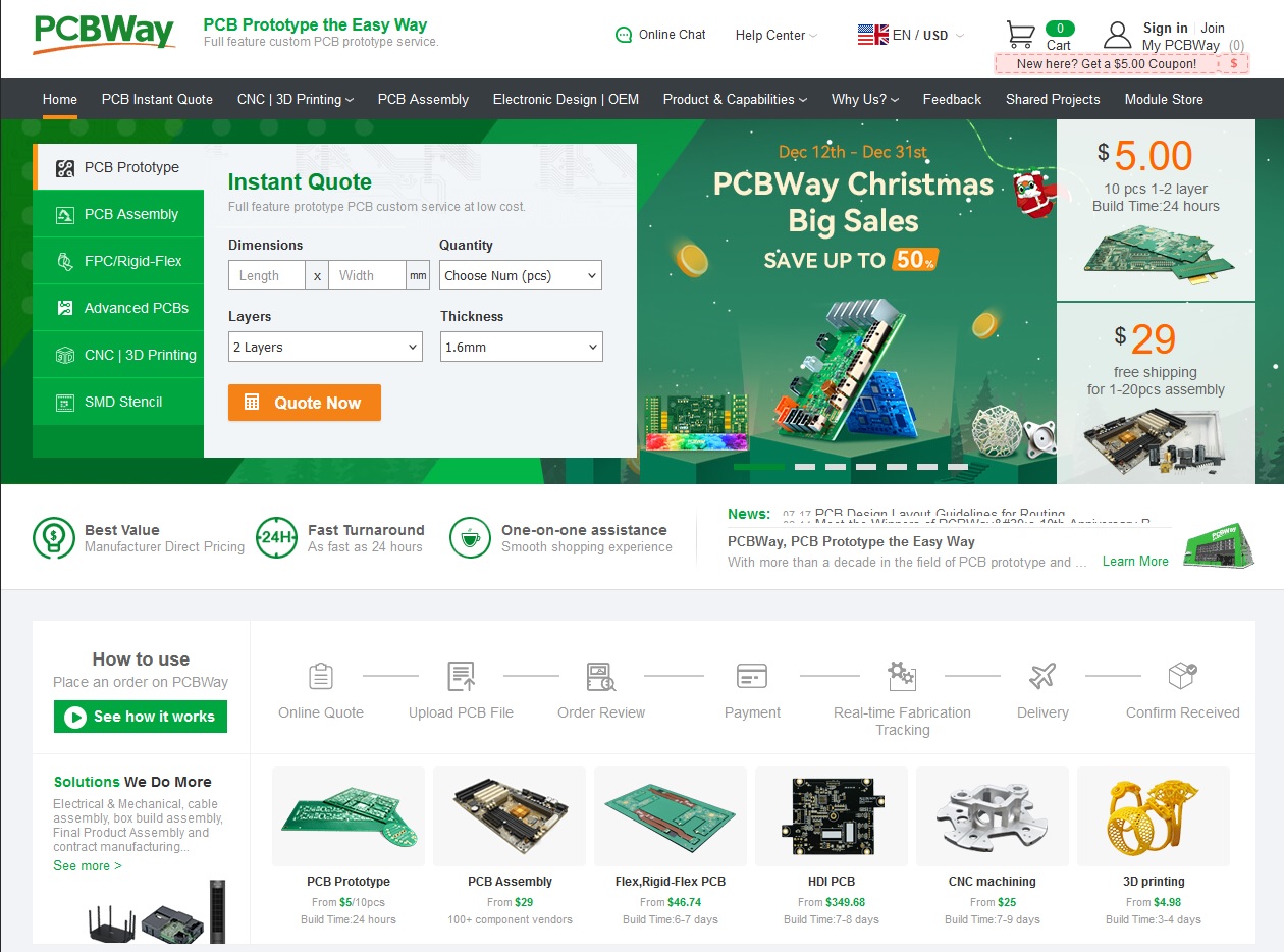
Brief aside for submitting my PCB to a design house!
After going through the board checker, I found that 10 of my boards would be ~5 dollars alone, although it would be $20 for shipping...
Home