This week, our assignment was called "made something big", and I made a nightstand. Originally, I had some ideas of creating a cabinet with a secret chamber using one of the methods described here. However, given the material's brittle physical properties, it would be hard to create such a cabinet without using fasteners or glue. Therefore, I decided to go with the simple two-shelf nightstand design.
Materials/Components
- Wood panels: two 4'x4' Oriented Strand Boards (OSB)
Machines/Tools
- CNC Shark Pro Plus Router
- 3/8'' router bit
- 1/4'' router bit
- Nail gun and plastic nails
- Orbital sander
- Rubber mallet
- Band saw & hand saw
Software Platforms
- CAD & CAM: Autodesk Fusion 360
Design Files
- CAD & CAM: f3d download
CAD
Parameters
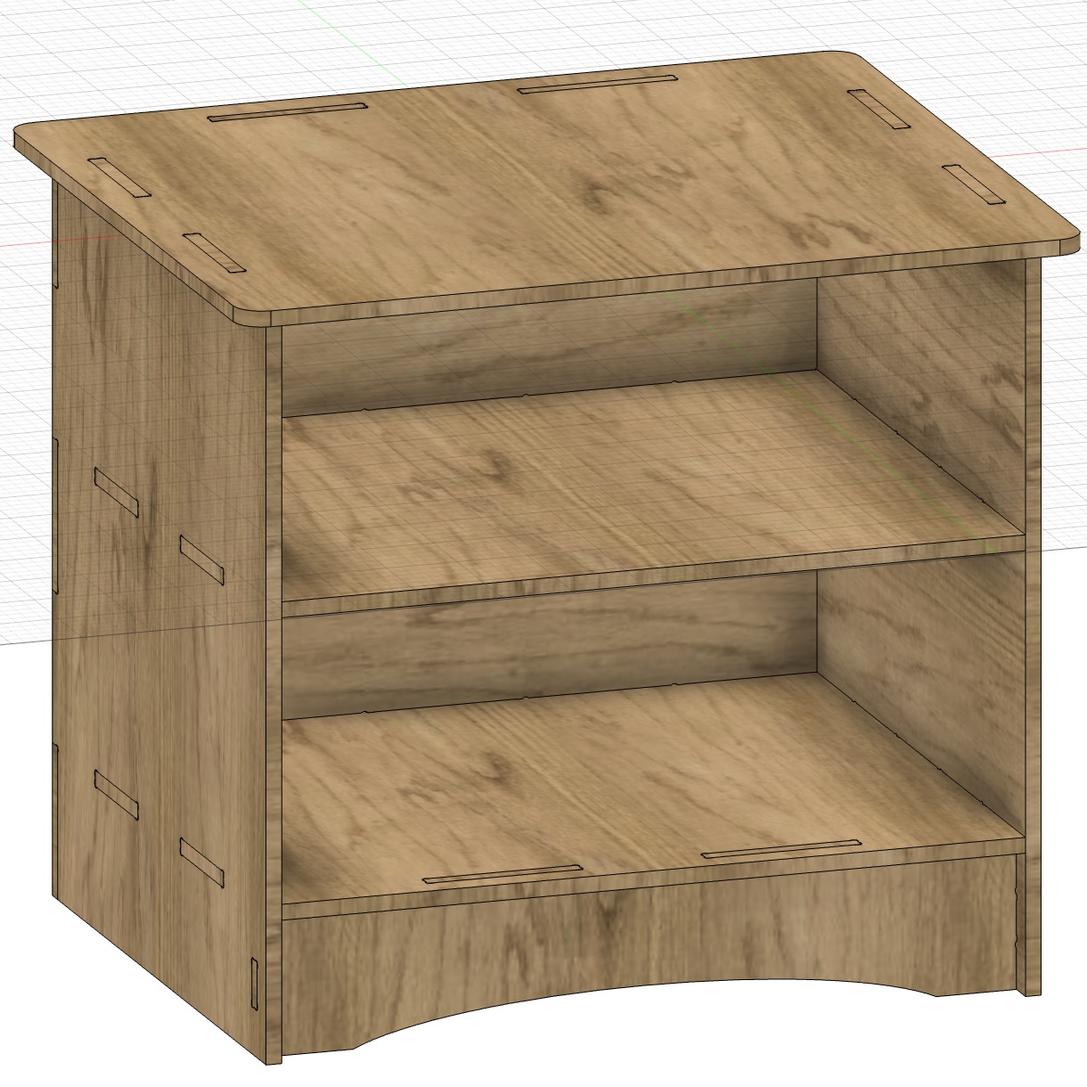
The design parameters were arbitrary (except the board thickness) as shown below:

Design
Having a general shape in mind, I designed the nightstand and added the joints in Fusion 360 just as in week 1. The difference this time was the addition of dogbones, because our round tool could not produce a square hole for the joints. This process was made easy by the Nifty Dogbone add-in for Fusion 360. The dogbones were made on all parts as "corner" type with a diameter of 1/4''. Compared with the dimensions of the design, the dogbones were barely visible:
CAM
After creating the design, all parts were laid down in the manufacturing model onto two 4'x4' boards using the "Arrange" command with an object spacing of 0.376'' (larger than the big tool's diameter) and a frame width of 1'':
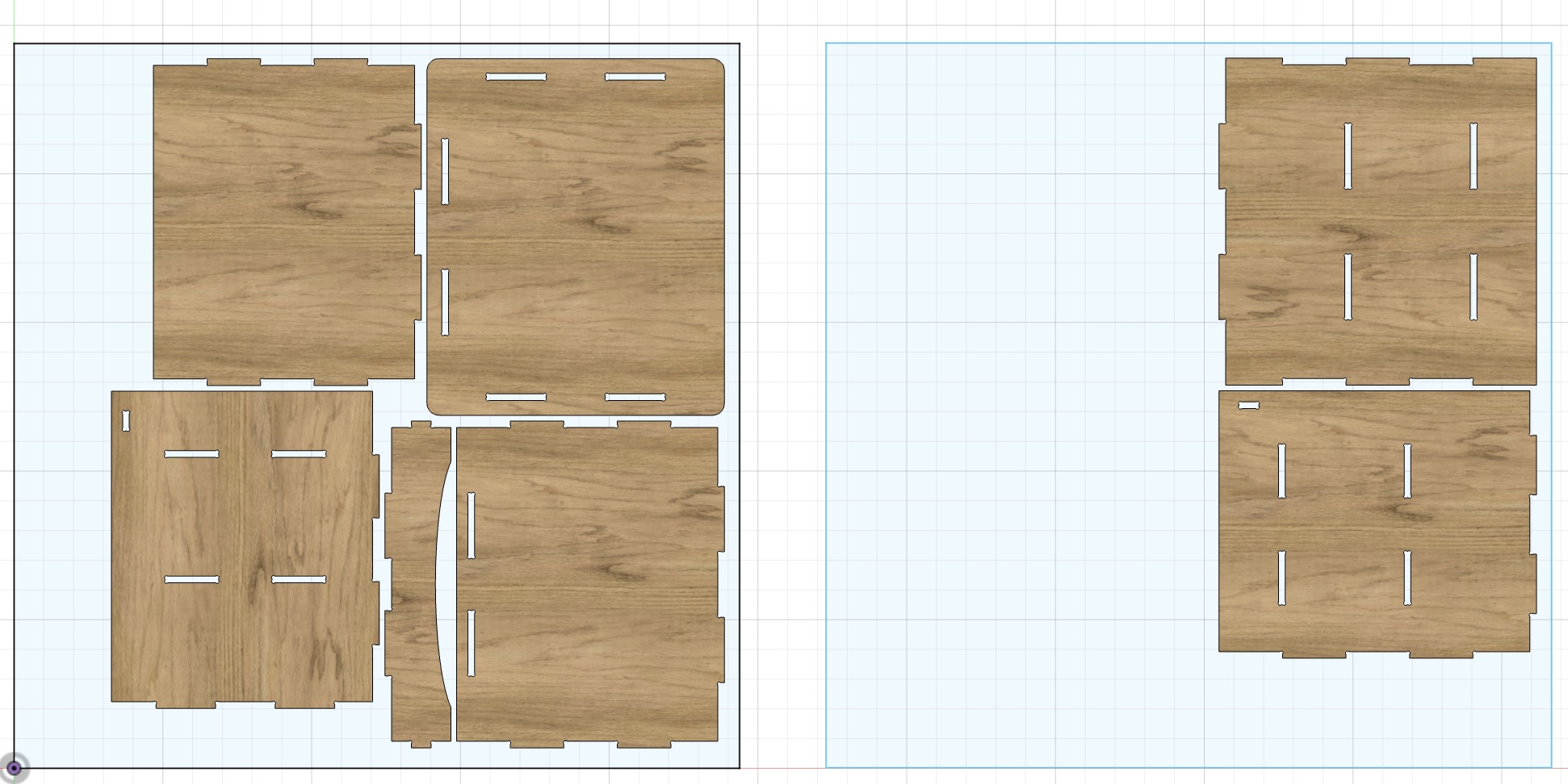
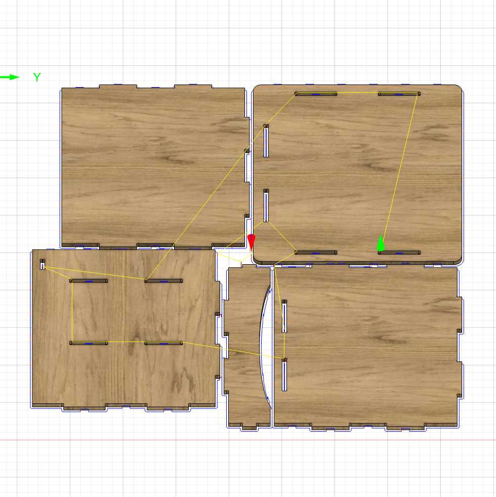
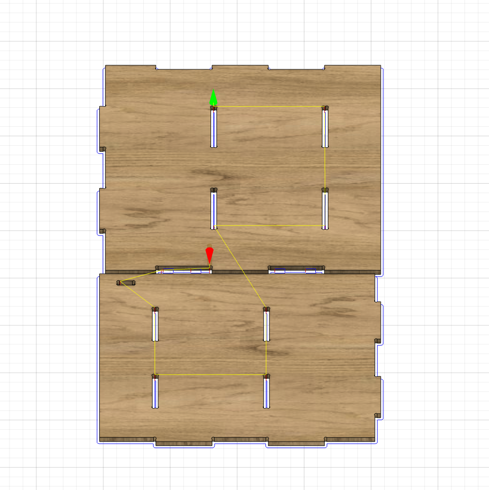
After doing CAM with the aligned parts, Anthony helped me refine it, and the resulting process for each board included two 2D-contours using a 3/8'' bit and a 1/4'' bit, respectively. The 3/8'' tool ran at 12000 RPM spindle speed with a feed rate of 120 inch per min (IPM), while the 1/4'' tool ran at 12000 RPM and 100 IPM. The 3/8'' tool was used to cut the outlines and inner holes, while the 1/4'' tool was used to cut the dogbones. The origins of the two setups were picked so that the cutting would be away from the operators for safety. The bottom heights were set to -0.04'' below the stock bottom to ensure the cut would go all the way through. The tab placements for the 3/8'' toolpath were shown below:
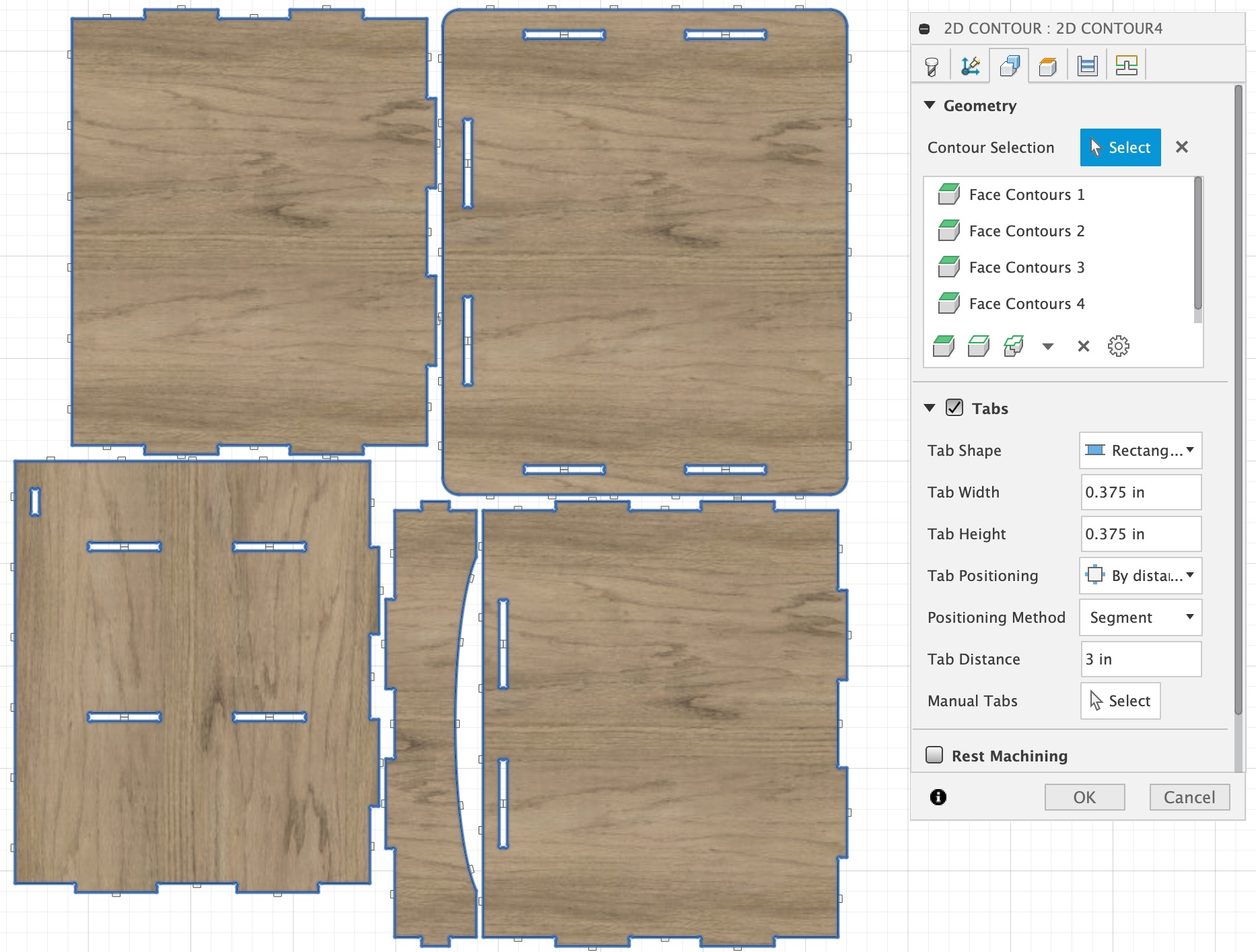
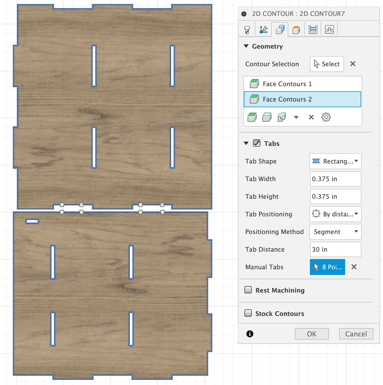
The tab positioning methods were set to "Segment" instead of "Contour" so that tabs wouldn't be generated at the corners. For big pieces as shown on the right, tabs were not necessary except some segments in between.
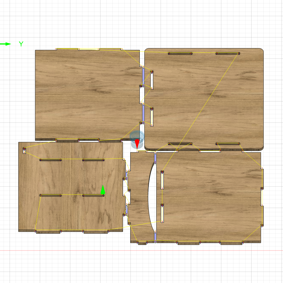
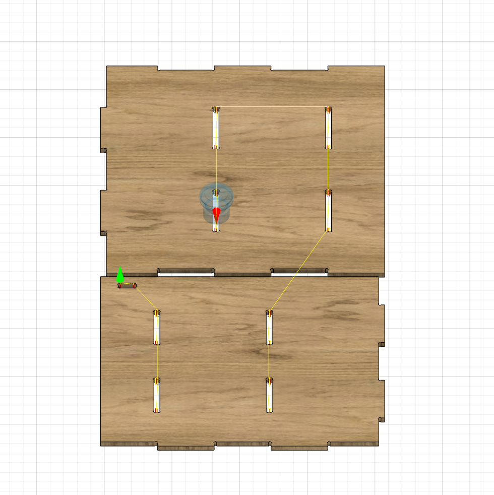
The resulting complete toolpaths were shown below:
Machining
The machining process was similar to week 6, except that this time we were cutting a much bigger material, so a different fixturing method was needed (other than holding down the material with hot glue).
This time, with the help of Anthony, I shot plastic nails into the boards using a nail gun. Around 7x7 nails were placed on each stock piece, with some additional ones on the corners to better secure the panel down. The stock material had some curvatures, so we had to start nailing from the middle and push the side of the panels down while shooting nails when we got close to the edges.
During cutting, one of the parts went loose from the bed, and we had to put more nails on it to secure it, but overall, the process went smoothly.
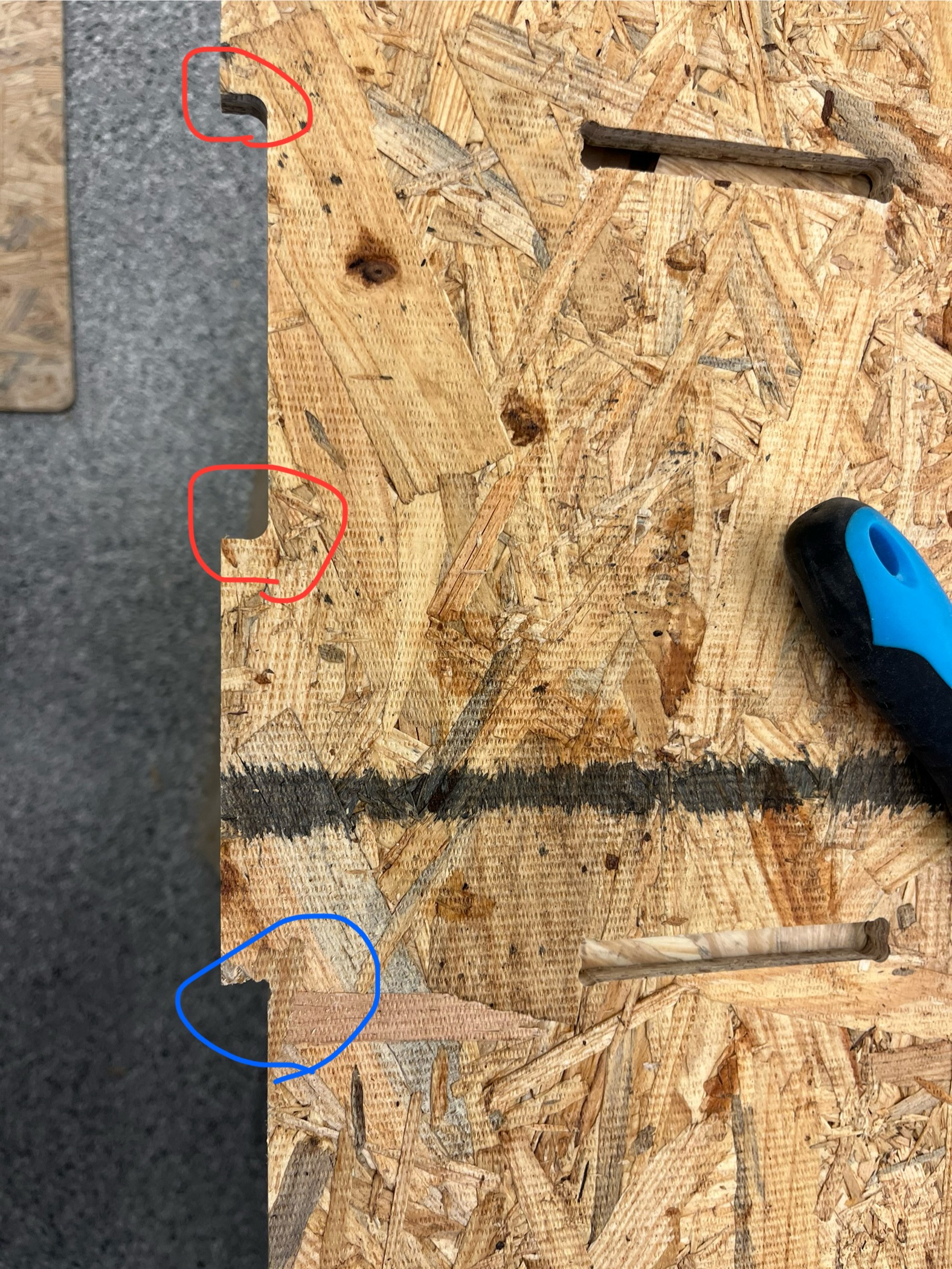
I was surprised that some parts came out without dogbones on the sides (but with dogbones in the inner holes), and I had to file the rounded corner to create rooms for the joints to fit:
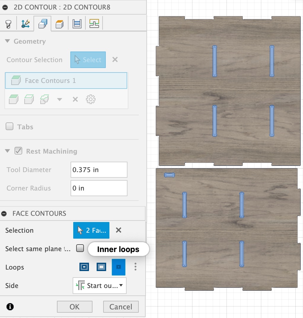
Later, I discovered that in the settings for the 1/4'' tool in my second setup, I picked the contours as "inner loops", because originally I was trying to have separate processes for the inner and outer features, but later when joining the two processes this was omitted. That explained why only the inner dogbones showed up in those two panels.
Surface Finishing
I didn't like the ink marks on the OSBs, so to make the surface a little better, I used an orbital sander to sand the surfaces. This made the markings a lot lighter.
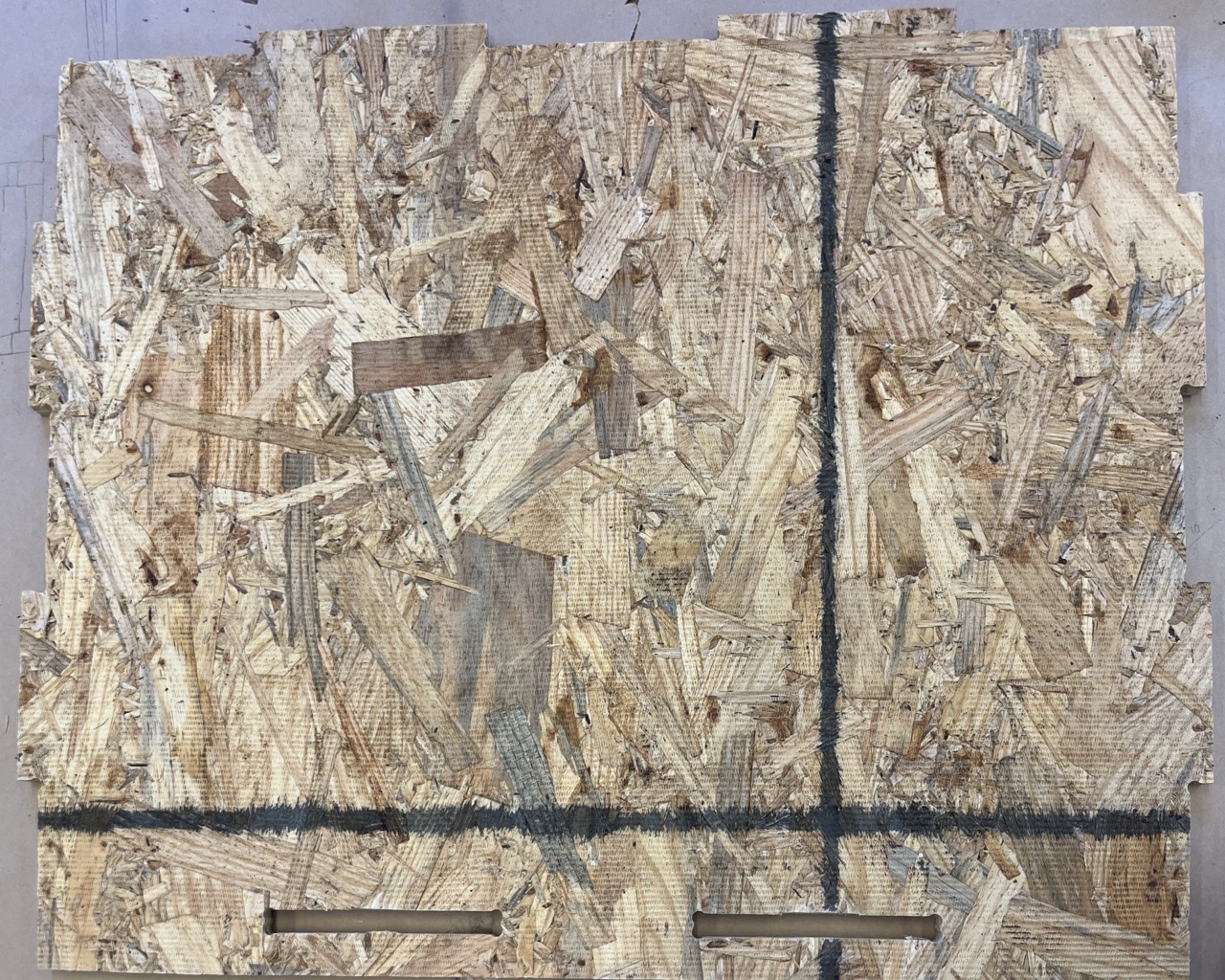
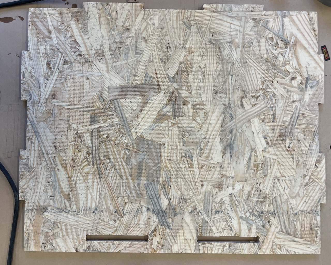
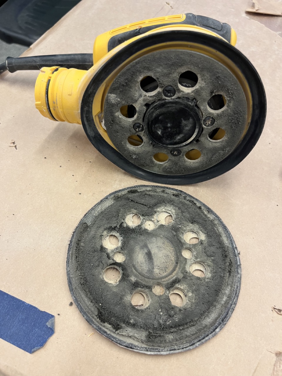
Unfortunately, the sander broke in the middle of the work, and I had one and a half board left unsanded (both sides of a side panel and one side of the top shelf).
Assembly
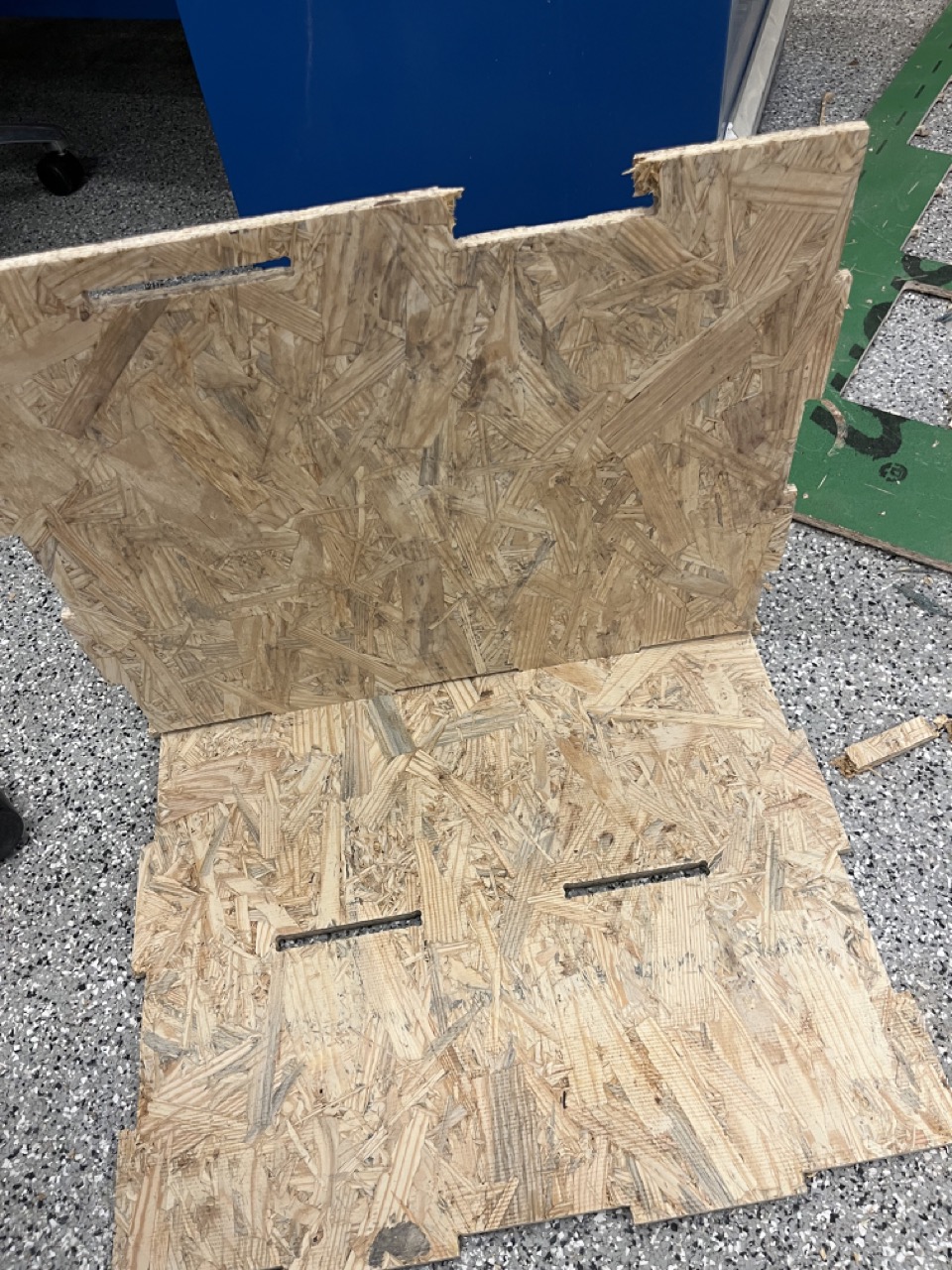
The sequence of assembly was important: back→top/bottom shelf→bottom/top shelf→apron→left/right→right/left→top. Several joints were quite tight, and I had to file some edges and/or use a rubber mallet to hammer them together. A bridge on the bottom shelf was accidentally broken during hammering, but I cleared the edges with a Western-style push saw, cut a piece of board of similar size using the band saw, and glued that piece on using wood glue.
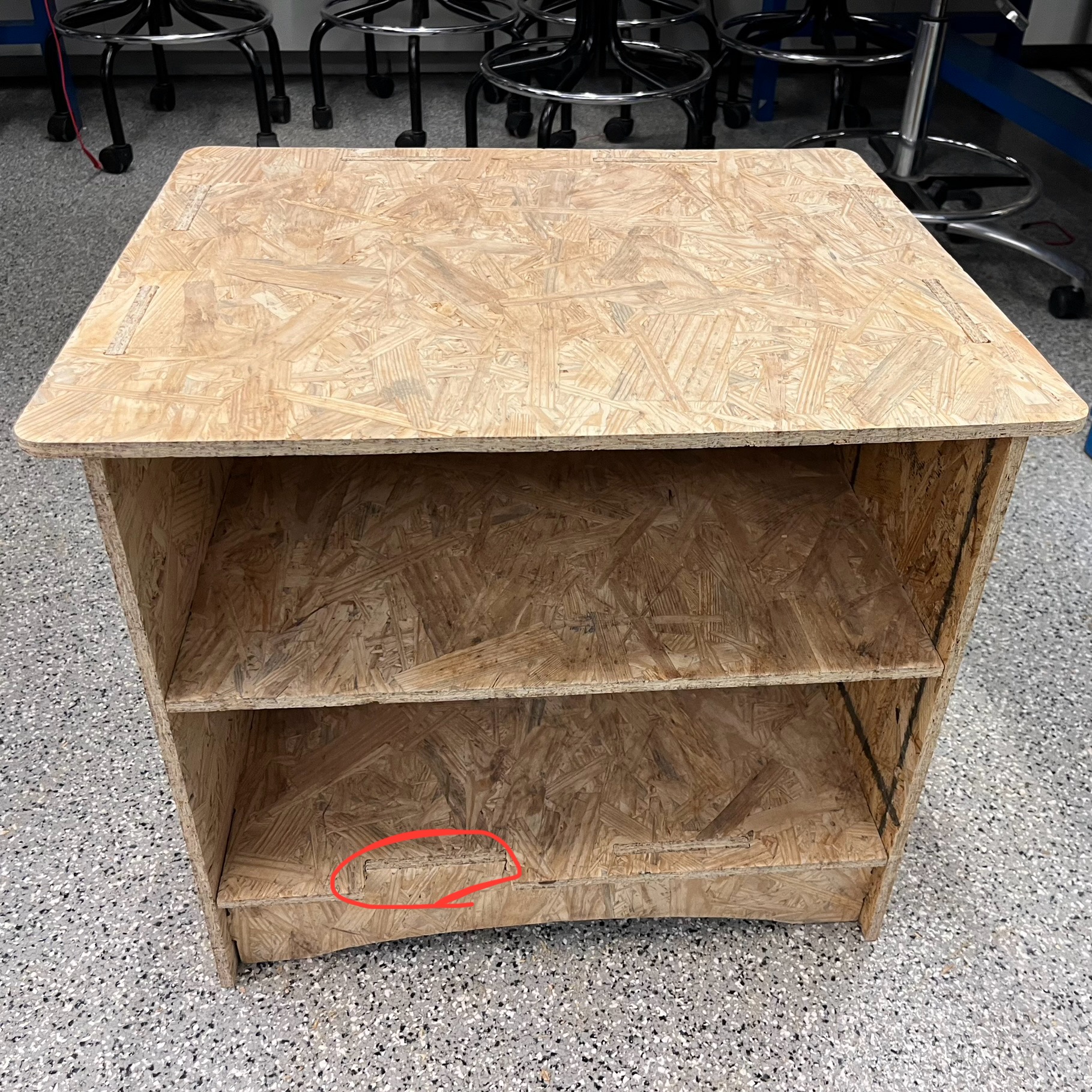
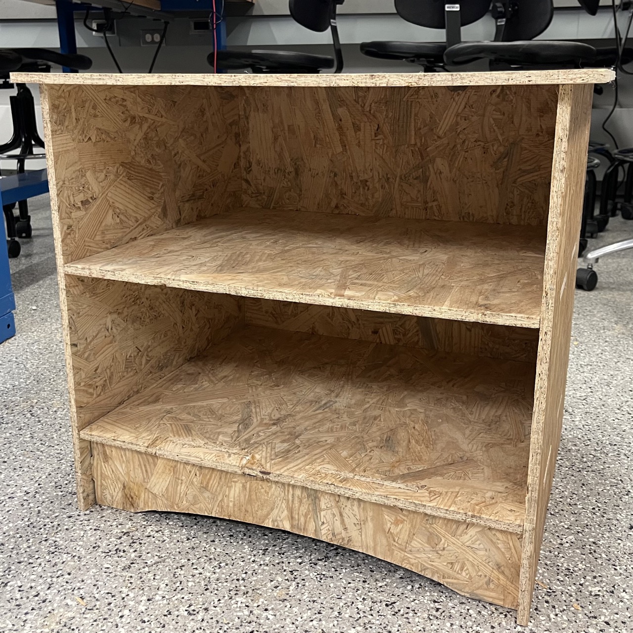
This nightstand was pretty stable and held my weight well!
Acknowledgements
I would like to thank Anthony for helping me revise CAM and with almost everything during machining and post processing with hands-on teaching. I really appreciate that he taught us not only how to do things, but also the reasons behind them, which I benefited greatly from.