06: Casting
Molding and casting week! Exciting! (Hopefully I don’t get sick this time)
Fusion Frustration
Now, just because we’re dealing with a machine that “will happily destroy you, itself, an[d] anything between where it currently is and where you tell it to go”, forcing us to use Fusion 360 to lock it down, doesn’t make Fusion any less frustrating.
I’m a Linux user, so there’s not a native version of Fusion 360 that just works. I tried:
- installing it using this repository. Clicking the sign-in button didn’t do anything.
- the snap verson. It results in some application not loading.
- the first one again, looking at issues and trying to find a solution that works. Too complicated.
- using flatpak and bottles, complete with these instructions to fix the sign-in issue (I was able to get Firefox to open a sign-in button, but that didn’t redirect back to Fusion 360 without following the aforementioned instructions), and changing the graphics engine to OpenGL to fix the issue with the viewport not rendering.
Even with all that,
-
saving is unstable - opening the properties menu takes a minute and I’m not exaggerating
- doing things like resizing the window, opening a new tab, or saving will turn the viewport gray if you roll a nat 1 on a d20
- the standard tool library is missing!
So I guess I have no choice but to use the online version, which lags when navigating and doing various actions. Needless to say, I will be designing my stuff elsewhere and importing the design into Fusion. This also has the bonus of not tying my designs to Fusion, which I didn’t want to do anyway.
Modular Mold
I wanted to try my hand at making modular molds: molds that can be combined to make customized casts. In particular, I wanted to make molds that can be combined to make digits.
Jigsaw Puzzle
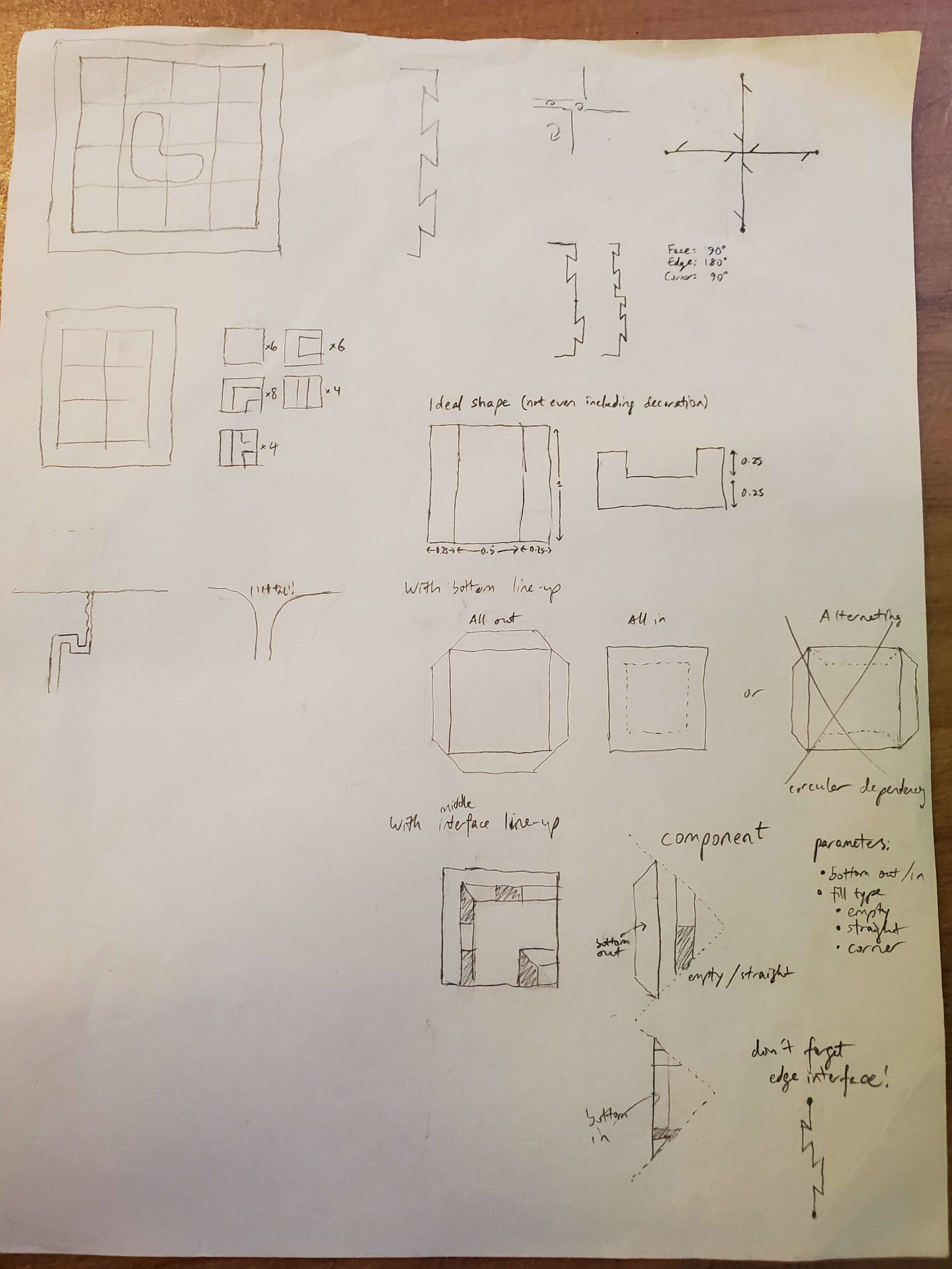
I needed to decide what interface to use for the edges. Initially, I wanted to go for a jagged edge pattern so the molds can hold each other together. Doing the symmetry (90° vertex symmetry, 180° edge symmetry, and 90° face symmetry) results in the edge interface needing 180° symmetry. Now, I did some CADing and pushed the edge interface to later. By the time I got to it, I realized that due to end mills not being able to reach sharp corners, this was going to be a lot more annoying than I thought. And then on second thought, when it’s time to clamp the molds together, it turns out that this jagged edge pattern might be a bad idea, actually:
So because of this and to save effort, I stuck with a flat edge interface.
Dots and Crosses (and Everything in Between)
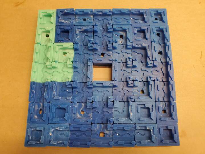
Now for the actual pieces. There are 6 types of pieces (some of which are the same in the laser cardboard alphabet!), one for each pattern you can make by connecting the center of a square to some edges; up to symmetry.
Each of these pieces needs a bottom-side mold and a top-side mold, and I wanted them to be the same because that would save wax room (wax block size is 3in×7in×1.5in). However, I also needed a mechanism to vertically align the molds. This would involve an octagon-square tessellation on the bottom sides of the molds. Octagons would get inserted first, then squares.
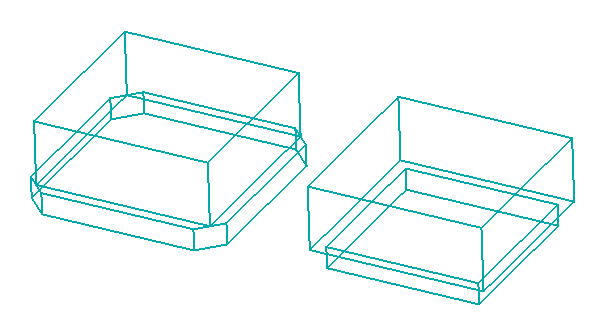
Unfortunately, the square piece would require a 2-sided wax mold, so I dropped the whole idea for now.
So time to make the pieces. Remember, the bottom and top molds for each piece should be the same, so the patterns of dips and bumps should be symmetric. This is the final design I came up with:

It’s called an End Mill, not a Corner Mill
Now for a fundamental fact about end mills: they can’t mill inverted corners. At least not ones with vertical edges. You’d either need increasingly-thin end mills (which are less sturdy), or a 5-axis machine (which we don’t have).
With this in mind, let’s take a look at the mold mold:
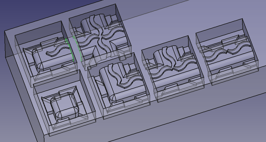
Look at all those sharp inverted corners! There’s ones in the bumps and dips, and there’s ones in the interfaces between molds! As it turns out, I don’t care about the inverted corners in the dips and bumps being sharp. There’s a nice property that not removing enough wax still allows the resulting molds to fit together (it’s removing too much wax that’s a problem). Besides, it’ll give a nice side decoration in the final cast. However, I very much care about the sharp inverted corners in the mold interfaces. It turns out that there’s another way to get sharp inverted corners, though. Dividing the original design at the sharp inverted corner, machining the parts separately, and putting them together. (This is what I did for those PUNT/TOOL letters way back when.) With that in mind, here’s the final mold mold:
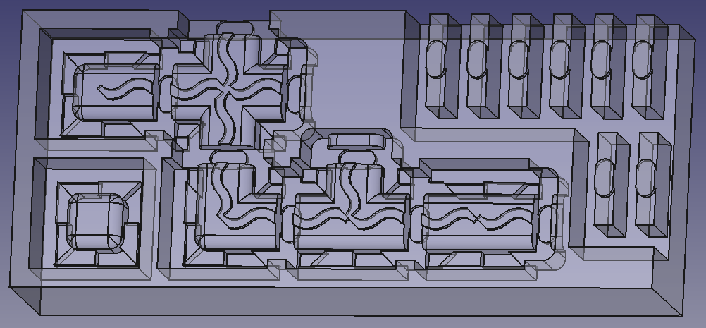
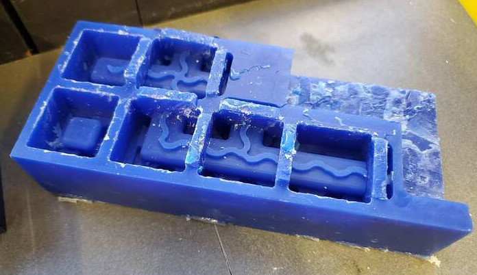
I just separated some walls to machine them separately. Afterwards, a vibrating cutter was used to cut them off so they could be attached. But first, machining.
Back to Fusion Frustration
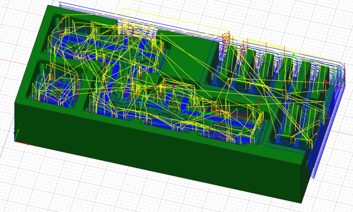
I exported the model as a STEP file (good for curves) and imported it into Fusion. I created a CAM toolpath using a 1/4-inch flat end mill and a 1/8-inch flat end mill. The 1/4-inch mill was for making bigger pockets and also cutting out the walls. (That wall area was deep so I didn’t want the 1/8-inch mill touching it. That’s also why there’s 0.25 inches of space between walls). I used the 1/8-inch mill for the rest of the job, including some parallels for the fillets.
Silicone
First comes making molds out of silicone. For the numbers, I needed 8 corner molds (a bunch of numbers have 4 corners, and each segment has a bottom mold and a top mold) and a bunch of other molds. So I made 8 copies total. I used Mold Star® Series Part A and Mold Star® 30 Part B for 7 of them and Mold Star® 15 SLOW Part B for one of them. Turns out that the Mold Star® 15 SLOW is less stiff, but it didn’t end up mattering. The mix ratio was 1:1. The time to cure was 6 hours, but can be reduced to 1-ish hours under a heat lamp, which I did. (Otherwise those 8 copies would take a while).
Stone
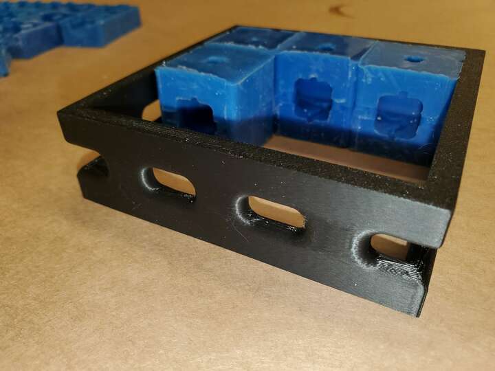
The process of making a mold out of stone was pretty long. First, I needed a clamping mechanism, which is shown below:

The design shown is the 3×3 version. For the numbers, I made a 2×3 version. Because of my designing, changing the 2×3 into a 3×3 was simple, except for the fact that I needed to redo the fillet on the walls. The inner dimensions of the clamp walls is the designed length of the mold times the number of molds intended to go on a side. This turns out to be enough clamping force.
And now, the process:
- Pick out the necessary molds
- For each pair of top/bottom mold, poke a hole in the center of the top one (if it doesn’t already have a hole). Make sure the bottom one doesn’t have a hole.
- Combine pairs
- Arrange the combined pairs hole-up backwards in the clamp walls. (The top side becomes the back side.)
- Check alignment using the windows in the clamp walls
- Tape the windows shut and tape the clamp floor to the clamp walls
- Put the clamp ceiling on and use doubled-up rubber bands to provide clamp force
- Mix water with drystone powder until the mixture looks a little rough when stirring it
- Pour the drystone mixture into a hole until it comes up out of all the holes. Pour a little extra at each hole to defend against contraction.
- Wait until solid and disassemble.
Here are some pictures of the process with a 3×3 clamp.
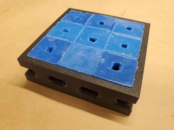
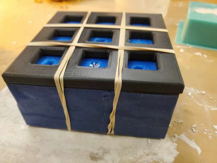
And now for some failures before I figured out a good process.
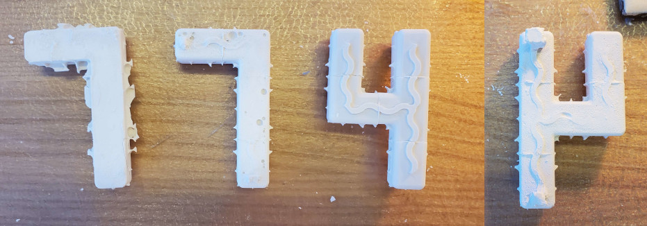
- Left: Stone mixture didn’t fill up all the way for some reason. Countermeasure: pour in extra drystone at each hole.
- Middle-left: Squiggly pattern wasn’t reached, probably caused by it being an overhead pocket with nowhere for air to escape to. Countermeasure: Make the holes actually touch the squiggly pattern. For that matter, assemble things backwards so the good side is the front side.
- Middle-right: Good front, but…
- Right: Stone mixture had trouble getting all the way through the squiggly pattern. Countermeasure: Make all the molds on the top side have holes.
And now for a success:
