Week 12: Networking and Communications
For this week, the individual assignment is to design, build, and connect wired or wireless nodes with network or bus addresses and include local input and/or output devices. For the group assignment, we have to send a message between two projects, ensuring everything communicates properly.
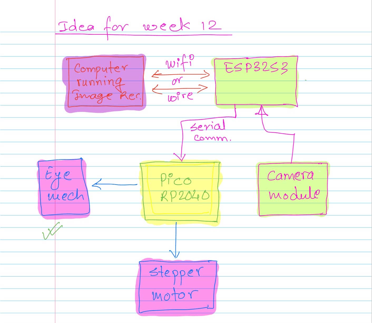
We are now less than four weeks away from the final project presentation. I thought, why not use this week as an opportunity to work on my final project and test the electronics I designed earlier? Also, why not aim high and see what can be achieved? My idea for the week is to use the board I designed during Week 9, which includes two microcontrollers: the ESP32S3 and the Raspberry Pi Pico. The detailed idea is shown in the following flowchart:

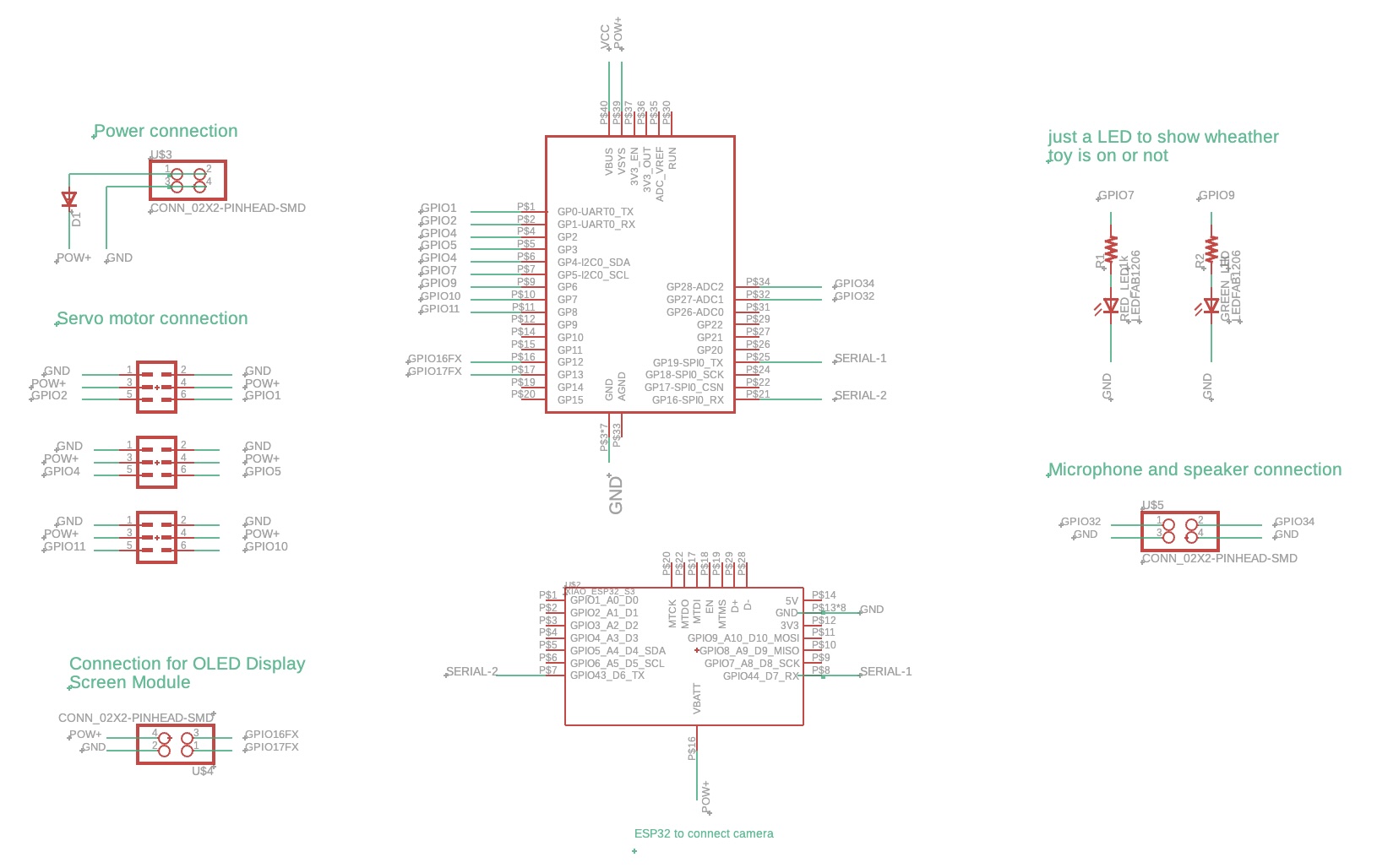
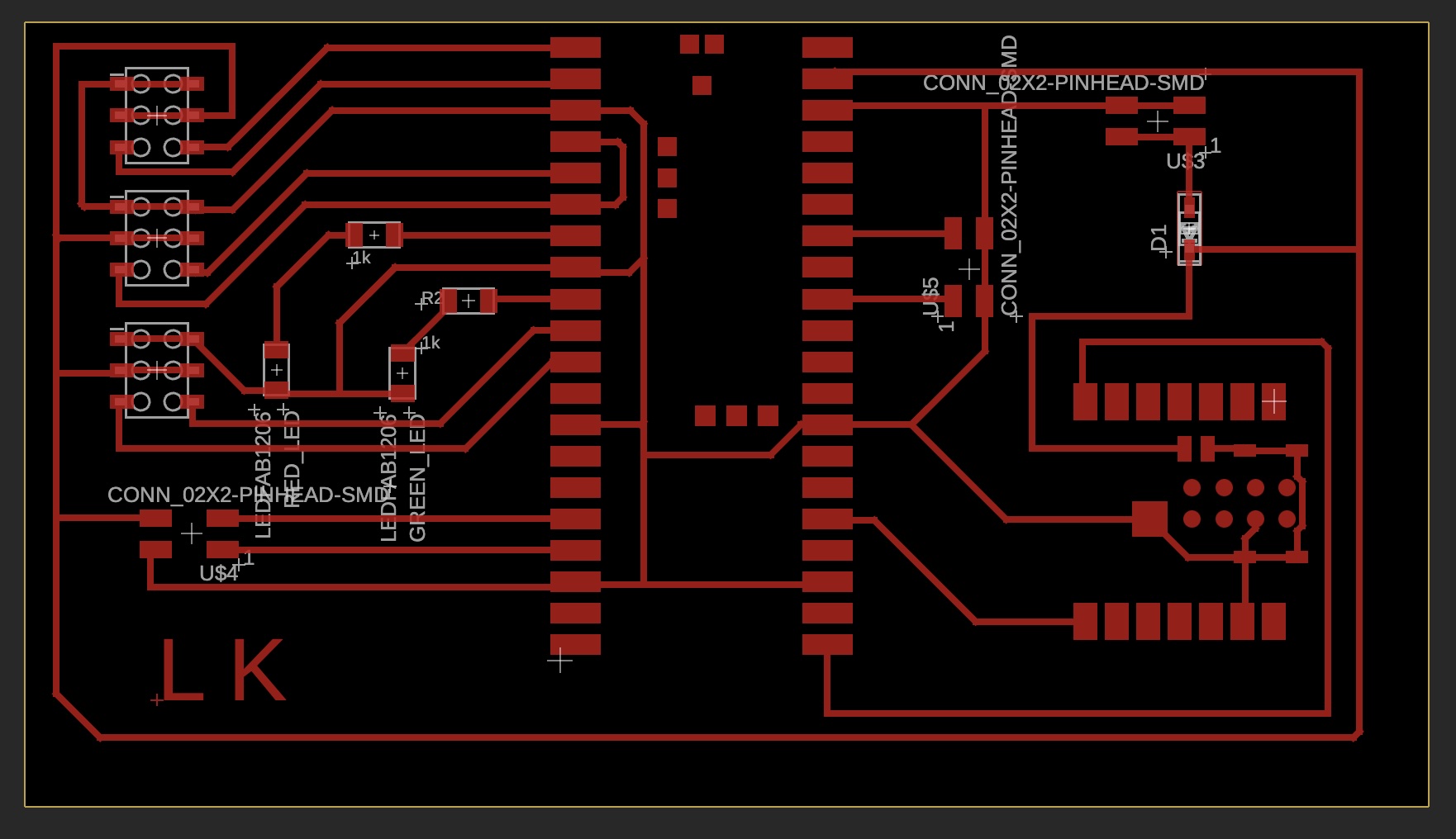
The schematic and PCB layout of the board are shown below:
Schematic

PCB

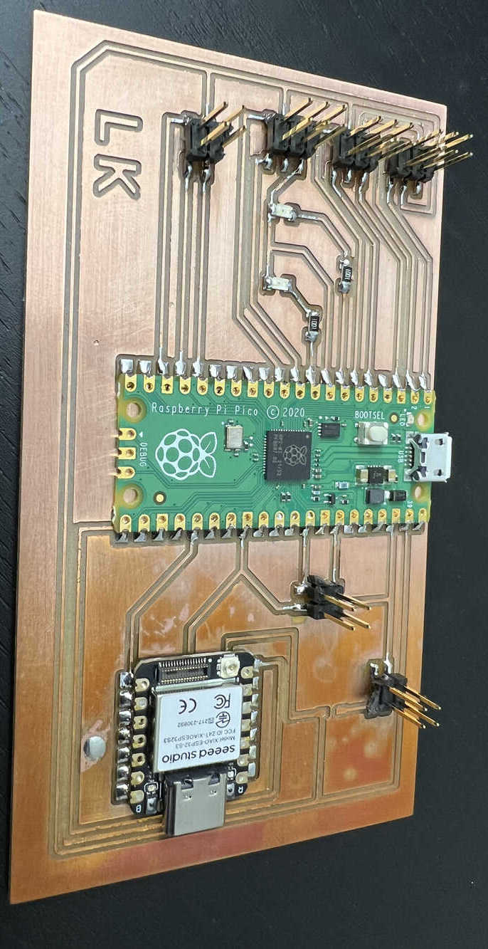
The board after the sholdering is given below, after carefully looking at the board I found out the TX and RX connection between Pico and the ESP32 was wrong. I solved this problem by using the jumper wire and cutting off the current wiring.

Detailed idea: the ESP32S3 will take input from the camera module and communicate with a computer running image analysis software, which detects the movement of objects in the video. Then, the computer will send commands to the ESP32, which will forward them to the Pico via serial communication to turn the eye left or right or make it blink. A stepper motor will be used to turn the entire rock mechanism. If time permits, I will include this part in this week's assignment; otherwise, I will tackle it in a later week.
This will be quite a task for me this week. Hence, I am starting with simple tasks first. My plan is to complete these tasks step by step and see how far I can progress. The first few steps focus on complying with the weekly assignment while also advancing the final project. Then I will add more complexity for the final project:
- 1. Test the ESP32S3 with the camera and Wi-Fi connection. Use the standard library code to broadcast the camera output to the PC.
- 2. Send message from Xiao ESP32S3 to Pico and do something.
- 3. Write PC code that instructs the ESP32S3 to go right, left, or blink. Forward that instruction to the Pico, which will drive the eye mechanism accordingly.
- 4. Advanced goal: Implement image recognition to track people’s movement and control the eye mechanism based on that. This involves taking image input from the ESP32S3 to the PC via Wi-Fi, analyzing the video on the PC, and sending movement instructions to the ESP32S3, which will then forward them to the Raspberry Pi Pico through serial communication.
Steps one and two will be sufficient for this week's assignment, while steps three and four are advanced work aimed at completing my final project.
Task 1: Test the ESP32S3 with the camera and Wi-Fi connection. Use the standard library code to broadcast the camera output to the PC.
ESP32S3 camera check, I wanted to check this first because I wanted to use the camera video feed to detect the motion using the vision algorithm.
2. Send message from Xiao ESP32S3 to Pico and do something.
This task is mainly to comply with the requirement for the week. First, I created a web server using HTML, which sends instructions through Wi-Fi to go left, right, or blink to the ESP32. These instructions are read by the Xiao ESP32S3 and displayed in the serial monitor to verify they were received correctly.
After confirming the web server worked, I focused on sending these instructions from the Xiao ESP32S3 to the Raspberry Pi Pico, which controls the eye mechanism. My initial attempt failed due to incorrect wiring. I had mistakenly connected the TX and RX pins to the SPI pins and used the UART0 protocol for communication, which was incorrect. After diagnosing the issue, I rewired the connections using jumper wires to properly route the TX and RX pins.
Despite fixing the wiring, it still didn’t work as expected. Sam and Yuval helped me troubleshoot further. They recommended starting with a simpler task, like blinking an LED using serial communication. Sam used an oscilloscope to analyze the data being sent by the ESP32, which helped us determine that the ESP32 was sending data, but the TX and RX definitions in the code were reversed. I updated the code to fix the TX and RX definitions, tested it again with the LED blinking example, and it worked successfully.
3. Write PC code that instructs the ESP32S3 to go right, left, or blink. Forward that instruction to the Pico, which will drive the eye mechanism accordingly.
With the LED working, I moved on to incorporating the eye mechanism code into the Raspberry Pi Pico. This involved integrating the movement commands from the web server into the existing eye mechanism code. Once implemented, the Pico successfully controlled the eye mechanism based on the web commands sent from my computer.
You can download the web page and code for the ESP32S3 and Raspberry Pi Pico here.
4. Advanced goal: Implement image recognition to track people’s movement and control the eye mechanism based on that. This involves taking image input from the ESP32S3 to the PC via Wi-Fi, analyzing the video on the PC, and sending movement instructions to the ESP32S3, which will then forward them to the Raspberry Pi Pico through serial communication.
This task has been a bit challenging for me to complete this week. Although I started by watching a few online tutorials, I found two particularly helpful videos: one by Makers Mashup and another by Jonathan R. I plan to use their algorithms in the coming week to bring my idea to life.