                               #include <Wire.h>
                                #include <Adafruit_GFX.h>
                                #include <Adafruit_SSD1306.h>

                                #define SCREEN_WIDTH 128  // OLED display width, in pixels
                                #define SCREEN_HEIGHT 64  // OLED display height, in pixels
                                #define OLED_RESET    -1  // Reset pin (not used with I2C)

                                Adafruit_SSD1306 display(SCREEN_WIDTH, SCREEN_HEIGHT, &Wire, OLED_RESET);

                                void setup() {
                                  // Set I2C pins for Raspberry Pi Pico
                                  Wire.setSCL(13);
                                  Wire.setSDA(12);
                                  Wire.begin();

                                  // Initialize the OLED display with I2C address 0x3C
                                  if (!display.begin(SSD1306_SWITCHCAPVCC, 0x3C)) {
                                    while (true) {
                                      delay(100);
                                    }
                                  }

                                  display.clearDisplay();
                                }

                                void displayText() {
                                  display.clearDisplay();
                                  display.setTextSize(1);
                                  display.setTextColor(SSD1306_WHITE);

                                  // Display the text "How to Make (almost) Anything"
                                  display.setCursor(0, 10);
                                  display.println("How to Make");
                                  display.setCursor(0, 20);
                                  display.println("(almost) Anything");

                                  // Display the text "Laxman Kafle"
                                  display.setCursor(0, 40);
                                  display.println("Laxman Kafle");

                                  display.display();
                                  delay(2000);
                                }

                                void displayRectangle() {
                                  display.clearDisplay();
                                  display.drawRect(10, 10, 100, 40, SSD1306_WHITE);  // Draw a rectangle
                                  display.display();
                                  delay(2000);
                                }

                                void displayTriangle() {
                                  display.clearDisplay();
                                  display.drawTriangle(64, 0, 0, 63, 127, 63, SSD1306_WHITE);  // Draw a triangle
                                  display.display();
                                  delay(2000);
                                }

                                void displayRoseAndPot() {
                                  display.clearDisplay();

                                  // Rose (simple approximation)
                                  display.fillCircle(64, 20, 10, SSD1306_WHITE);   // Rose flower
                                  display.drawLine(64, 30, 64, 50, SSD1306_WHITE); // Stem

                                  // Pot (simple rectangle representation)
                                  display.drawRect(54, 50, 20, 10, SSD1306_WHITE);  // Pot

                                  display.display();
                                  delay(2000);
                                }

                                void loop() {
                                  displayText();
                                  displayRectangle();
                                  displayTriangle();
                                  displayRoseAndPot();
                                }
Week 9: Output devices
This week's individual assignment is to add an output device to the microcontroller board designed previously or new one and to program it to perform a task. For the group assignment, we need to measure the power consumption of an output device. I think this week provides a great opportunity to make progress on my final project, incorporating it into this assignment.
One of the main output devices for my project will be a servo motor, which will control various parts from the eye mechanism to rotating the entire rock structure. This is the perfect time for me to test that out. I’ve been working on designing the eye mechanism over the last few weeks. Although it’s still not perfect, I plan to refine it further this week, using the servo motor to bring it to life.
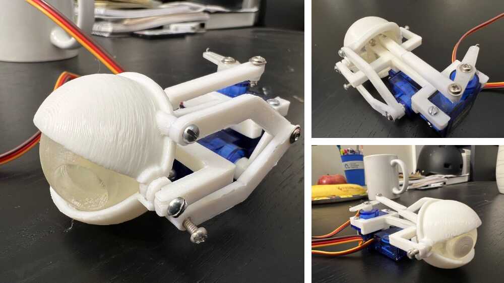
I began this assignment by updating my eye mechanism design, which I’ve been developing slowly over the past few weeks. It still needed adjustments before advancing to the next stage, so I dedicated two days to modifying the design. Now, it appears ready for the next steps.
I 3D-printed the updated design using both the FormLab SLA printer and the Prusa printer. After assembly, the mechanism showed improvements over previous versions.
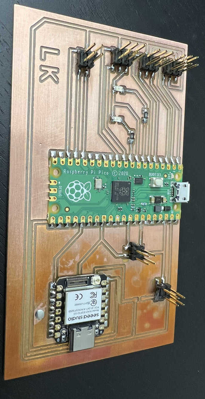
Next, I started designing the PCB board. I had previously designed a PCB during Week 6: Electronic Production, but I made further modifications to improve the design. The new PCB includes connection points for four motors to drive the eye mechanism, one motor to rotate the rock structure, and output connections for the OLED display. It also has ports for a microphone and speaker. The ESP32S3 microcontroller has a camera port built-in, so no additional design is needed for that. Additionally, I included a serial port to enable communication between the ESP32 and a Raspberry Pi Pico, as well as a connection for an external power source.
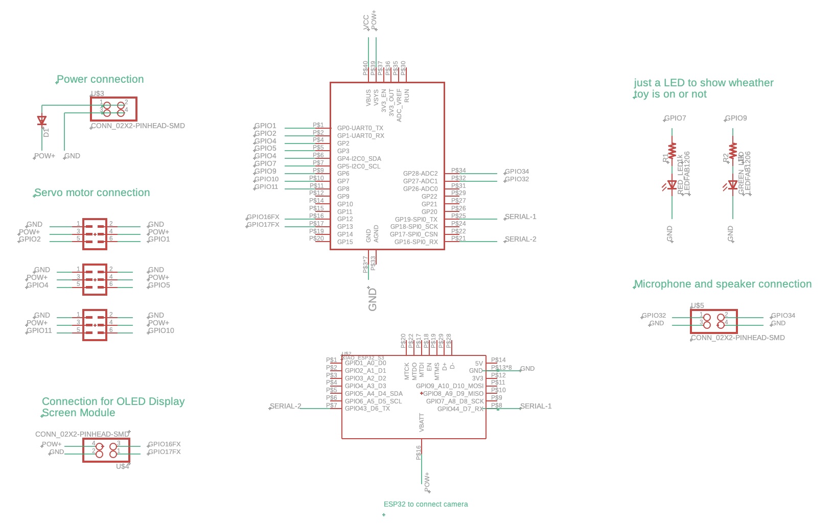
PCB
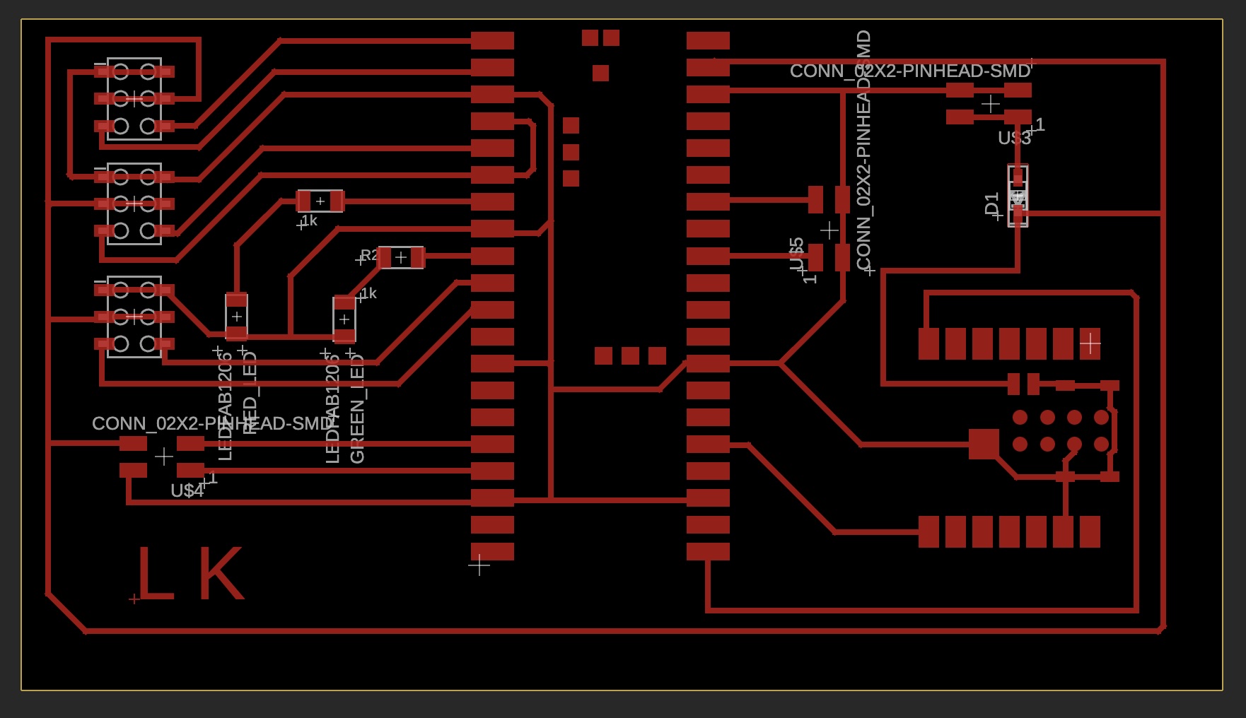
After finalizing the design, I milled the PCB and began hand-soldering the components. However, since the ESP32S3’s external power input ports are located on the underside, I needed to use a reflow process for accurate soldering. Below, you can see the solder paste applied on the PCB before reflow.
I also applied a small amount of solder paste on the side of the board for visual confirmation. The idea is that if the paste under the board and on the side melts simultaneously, I’ll have visual verification that the reflow soldering is successful.
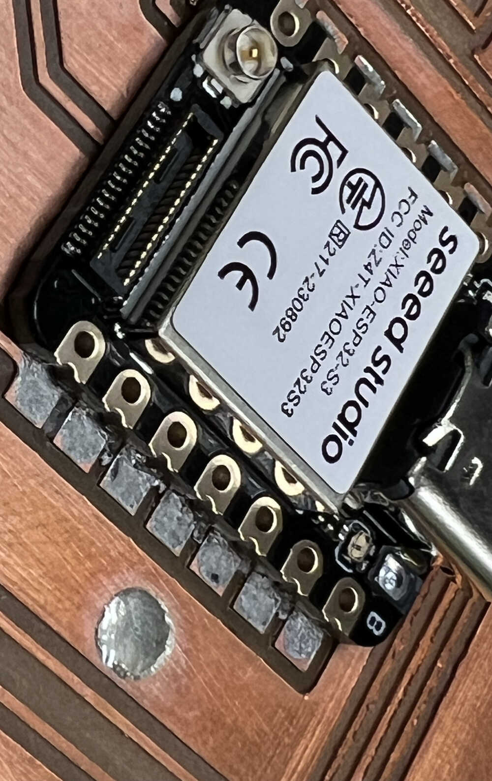
The solder paste on the side didn’t seem sufficient initially, so I used a handheld soldering iron to add more solder where needed.
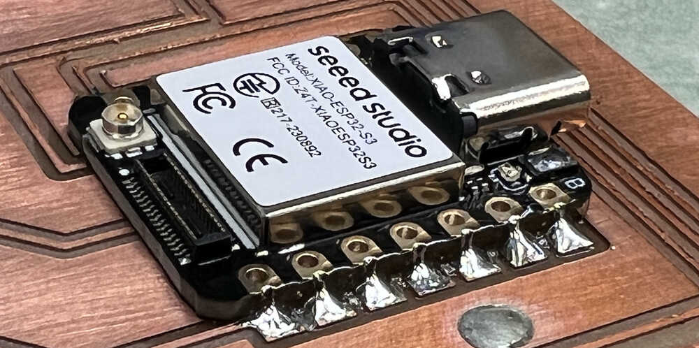
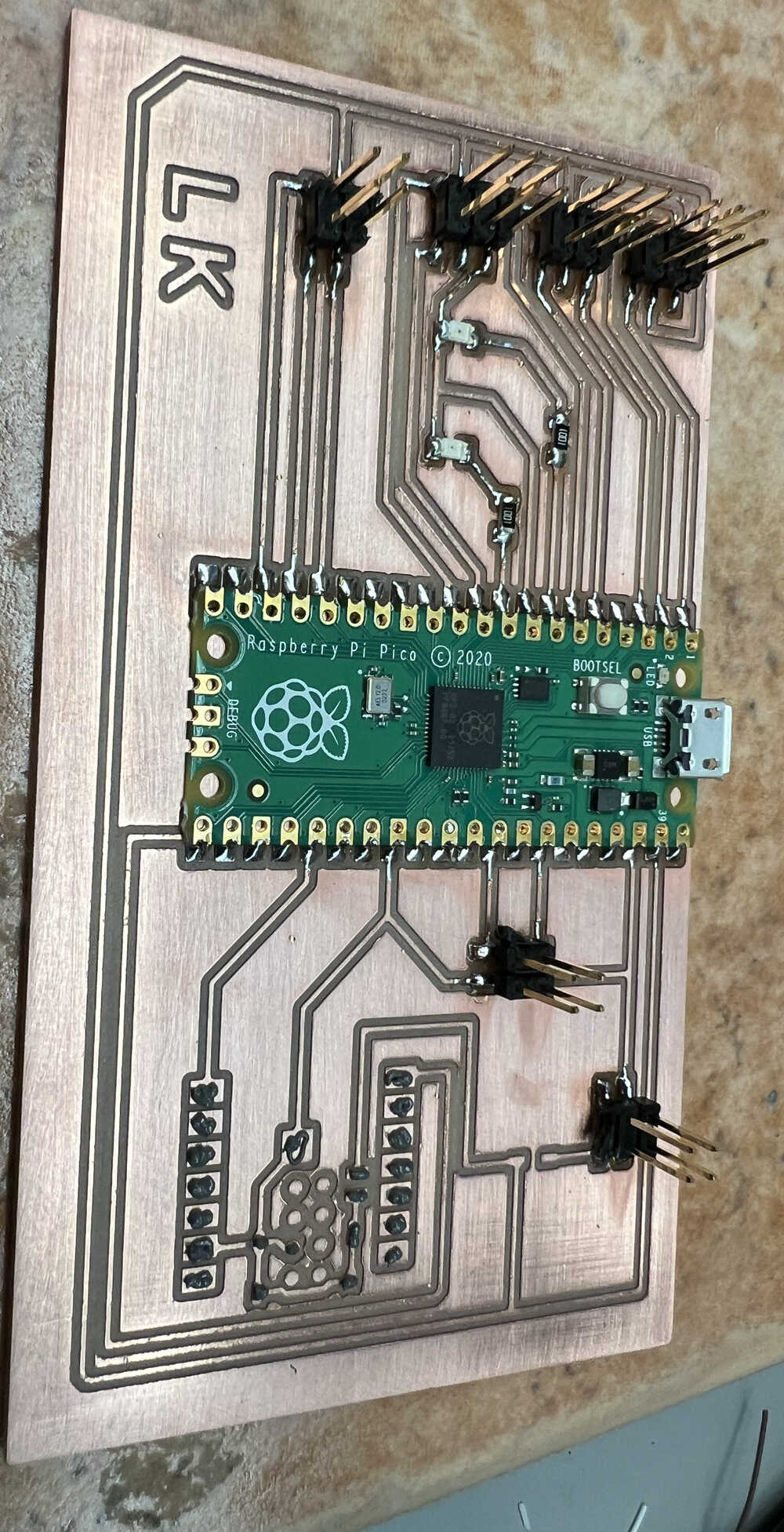
After completing the soldering, this is how the final PCB board looks:
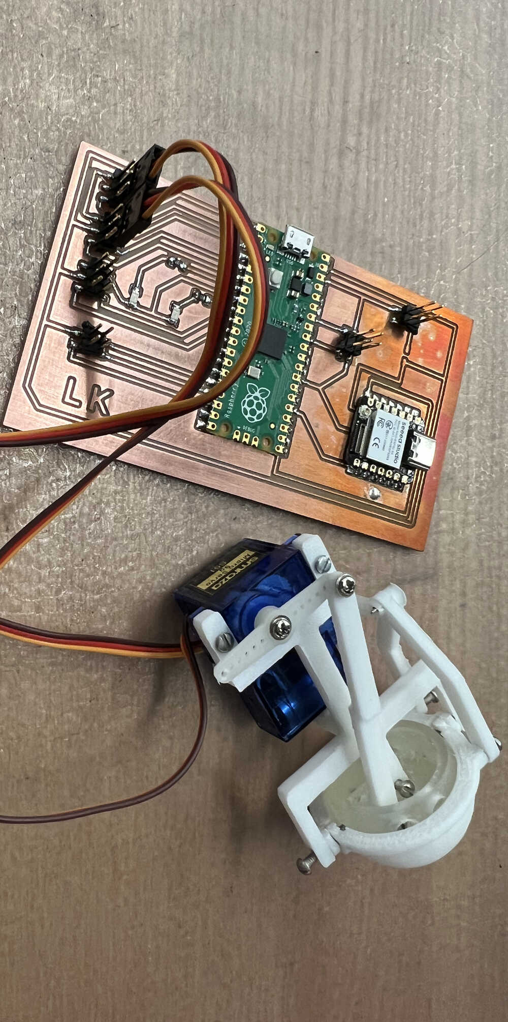
Finally, I connected the eye mechanism to the board. The next step will be to write the code to control it and begin testing.
I am starting to test each component one by one. First, I am testing the Pico with the OLED display. I tried using GIMP to convert my photo into C-code to display it on the OLED, but it didn't work. I think the resolution of the OLED (128 px by 64 px) isn't sufficient to display the image properly. I followed this YouTube tutorial. Now, I am certain that both the OLED display and the Pico are working correctly. If you want to try it yourself, here is the code.
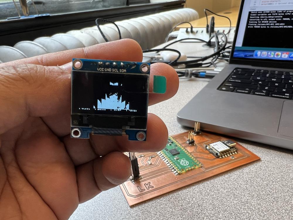
I also printed some simple shapes on the display.
Next, I am controlling the eye mechanism using the servo motors.
First, I checked whether the servo motors were working properly. To do this, I rotated the servo motors from 0 to 180 degrees without attaching any load.
Servo Motor for Eyeball Movement:
Servo Motor for Eyelid Movement:
In the full assembly, I have two servo motors connected to the Raspberry Pi Pico. The first servo is connected to the eyeball (GPIO 0), and the second one is connected to the eyelid (GPIO 3). My eye mechanism doesn't need a full 180-degree rotation. The servo that drives the eyeball might only need a total of 15 degrees of rotation, making 7.5 degrees the central position so that it can rotate both ways. Alternatively, I could make 90 degrees the central position and rotate +7.5 and -7.5 degrees around it. The motor that drives the eyelid also doesn't need a full rotation; from the zero position, it might need about 10 degrees of rotation. The exact values will be determined after several trials, but for the first trial, I am going with this setup.
                            // Define GPIO pins for servos
                            const int servo1Pin = 0;   // Connect the first servo to GPIO 0
                            const int servo2Pin = 3;   // Connect the second servo to GPIO 3

                            // Define pulse width range for 0 and 180 degrees in microseconds
                            const int minPulseWidth = 1000;   // Pulse width for 0 degrees (1 ms)
                            const int maxPulseWidth = 2000;   // Pulse width for 180 degrees (2 ms)
                            const int refreshInterval = 20;   // 20 ms interval between pulses (50Hz frequency)

                            void setup() {
                              // Set servo pins as outputs
                              pinMode(servo1Pin, OUTPUT);
                              pinMode(servo2Pin, OUTPUT);
                            }

                            void loop() {
                              // Sweep from 0 to 180 degrees
                              for (int angle = 0; angle <= 180; angle++) {
                                setServoAngle(servo1Pin, angle);
                                setServoAngle(servo2Pin, angle);
                                delay(15);  // Smooth movement delay
                              }

                              delay(500);  // Pause before reversing direction

                              // Sweep back from 180 to 0 degrees
                              for (int angle = 180; angle >= 0; angle--) {
                                setServoAngle(servo1Pin, angle);
                                setServoAngle(servo2Pin, angle);
                                delay(15);  // Smooth movement delay
                              }

                              delay(500);  // Pause before repeating
                            }

                            // Function to set servo position based on an angle (0 to 180 degrees)
                            void setServoAngle(int pin, int angle) {
                              // Map angle (0-180) to pulse width (1000-2000 microseconds)
                              int pulseWidth = map(angle, 0, 180, minPulseWidth, maxPulseWidth);

                              digitalWrite(pin, HIGH);           // Set the pin high
                              delayMicroseconds(pulseWidth);     // Hold high for the calculated pulse width
                              digitalWrite(pin, LOW);            // Set the pin low

                              delay(refreshInterval - (pulseWidth / 1000));  // Wait for the rest of the refresh period
                            }
The first try seems quite promising. Now, I need to refine my code to make the movement appear more natural.
I designed and printed the casing for the eye mechanism and gave the code a little makeover. Now it’s absolutely adorable! Don’t believe me? Take a look for yourself... prepare for cuteness overload!
                            #include <Servo.h>

                            // Define servo objects
                            Servo eyeballServo;
                            Servo eyelidServo;

                            // Define GPIO pins
                            const int eyeballPin = 0;
                            const int eyelidPin = 3;

                            // Define rotation angles and speeds
                            const int eyeballHome = 20;           // Set midpoint for eyeball as 90 degrees
                            const int eyeballRotation = 30;        // Eyeball rotation range (7 degrees each direction for subtle movement)
                            const int eyelidOpen = 0;             // Eyelid open position
                            const int eyelidClosed = 60;          // Eyelid closed position
                            const int moveDelay = 15;             // Delay for smoother, slower movement

                            void setup() {
                                // Attach servos to pins
                                eyeballServo.attach(eyeballPin);
                                eyelidServo.attach(eyelidPin);

                                // Set initial positions
                                eyeballServo.write(eyeballHome);    // Move eyeball to home position (90 degrees)
                                eyelidServo.write(eyelidOpen);      // Set eyelid to open position (0 degrees)
                            }

                            void loop() {
                                // Simulate a natural blinking movement
                                blinkEyelid();

                                // Simulate natural eyeball movement with pauses
                                moveEyeball(eyeballHome + eyeballRotation);   // Look right
                                delay(1000);                                  // Pause
                                moveEyeball(eyeballHome - eyeballRotation);   // Look left
                                delay(1000);                                  // Pause
                                moveEyeball(eyeballHome);                     // Return to center
                                delay(1500);                                  // Longer pause before next blink
                            }

                            // Function to simulate smooth eyelid blinking
                            void blinkEyelid() {
                                for (int pos = eyelidOpen; pos <= eyelidClosed; pos++) {
                                eyelidServo.write(pos);  // Close eyelid slowly
                                delay(moveDelay);        // Small delay for smooth motion
                                }

                                delay(200);  // Pause with closed eyelid to simulate a blink

                                for (int pos = eyelidClosed; pos >= eyelidOpen; pos--) {
                                eyelidServo.write(pos);  // Open eyelid slowly
                                delay(moveDelay);        // Small delay for smooth motion
                                }
                            }

                            // Function to simulate smooth eyeball movement
                            void moveEyeball(int targetPosition) {
                                int currentPosition = eyeballServo.read();
                                int step = (currentPosition < targetPosition) ? 1 : -1;  // Determine movement direction

                                for (int pos = currentPosition; pos != targetPosition; pos += step) {
                                eyeballServo.write(pos);
                                delay(moveDelay);  // Delay for smoother, gradual movement
                                }
                            }
Learning to Use Stepper Motor
I wanted to use a stepper motor for my final project, but I hadn’t had the opportunity to test it earlier. So, after finishing my first project, I had some time left, and I decided to take this on as a second task for the week.
Stepper motors are a type of electric motor that move in precise, fixed steps rather than rotating continuously like traditional motors. They’re ideal for precise control in equipment like 3D printers and CNC machines. I chose to use the stepper motor 17HE15-1504S. I reviewed its datasheet to understand its specifications. Stepper motors operate based on electromagnetism, allowing for precise rotational control through discrete steps. For example, my motor has 200 steps per rotation, which can be divided further into smaller steps using half-step or microstepping by adjusting the voltage across the coils. This allows for smooth rotation and very precise control. Additionally, one advantage of stepper motors is that they lock into position after rotating, providing stable control.
Alongside the motor, we need a stepper motor driver or H-Bridge to run it. This is because stepper motors rotate based on changing electromagnetic fields, achieved by alternating the current polarity in the coils, a process managed by an H-Bridge. Anthony explained how each MOSFET works to rotate the motor and why it’s called an H-Bridge. The stepper motor I’m using is bipolar, which requires a dual H-Bridge, so I decided on the DRV8428. It includes a dual H-Bridge internally and supports microstepping. After reading the datasheet, I found a typical application diagram to use as a guide. I showed my diagram to Anthony, who suggested grounding pin 17 (the large pad under the board) and helped me correct a few mistakes.
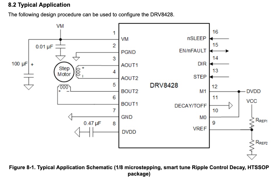
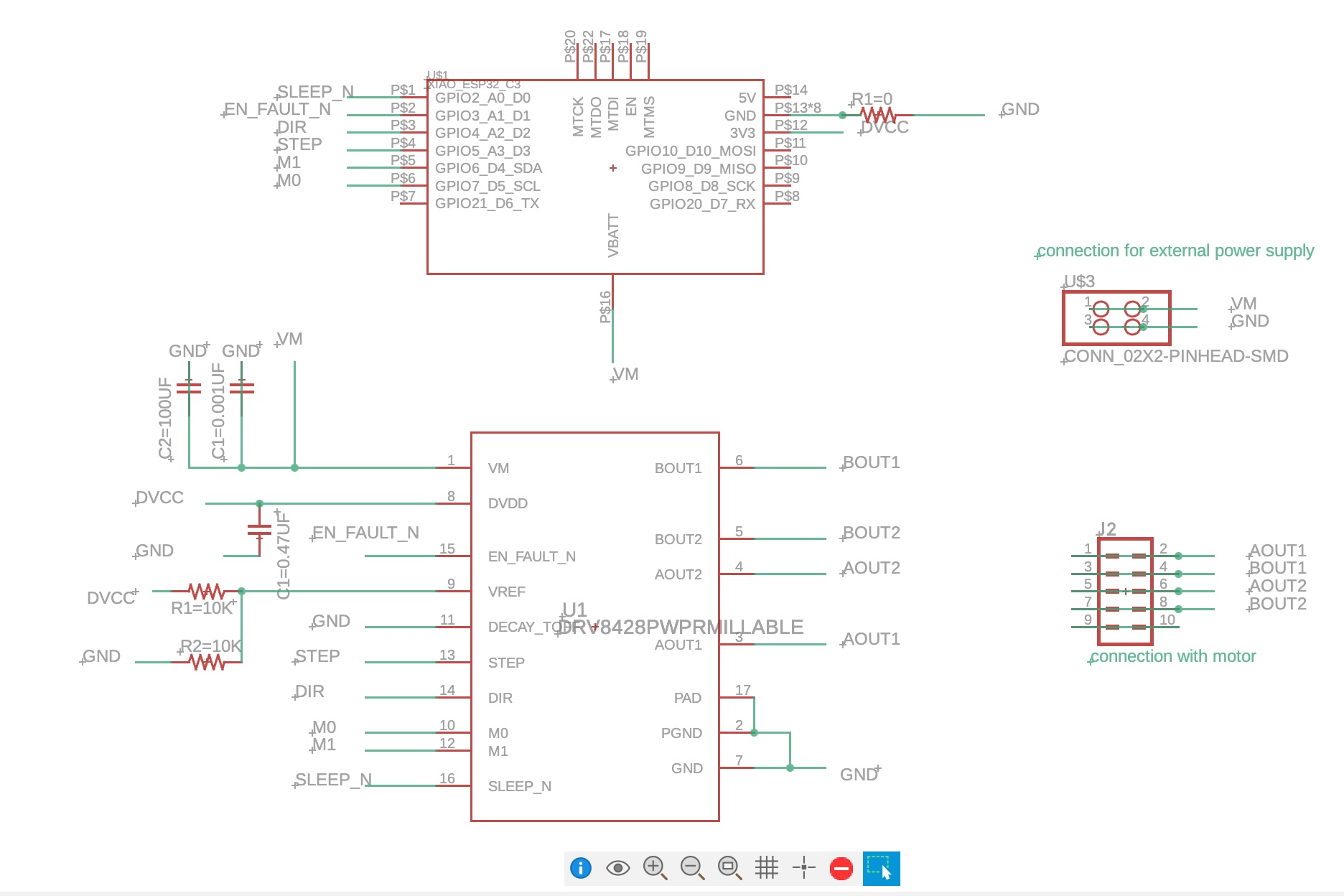
Then I went ahead and designed a board for it. My board includes an Xiao ESP32C3 microprocessor, a 4-pin connection for the stepper motor, and a connector for an external power supply.
The most challenging part of the PCB design was routing the tiny wires from the DRV8428. I ended up reducing the copper trace width to 10 mils and the clearance to 12 mils, which seems workable with 1/64" and 1/32" end mills. Technically, traces narrower than 16 mils shouldn’t be milled with a 1/64" end mill, but by setting the PCB conservatively and using a knife to clear corners missed by the end mill, it worked—tricky but effective!
Only the copper around the DRV8428 had a reduced size; elsewhere, the copper trace width and clearance remained at the standard 16 mils.
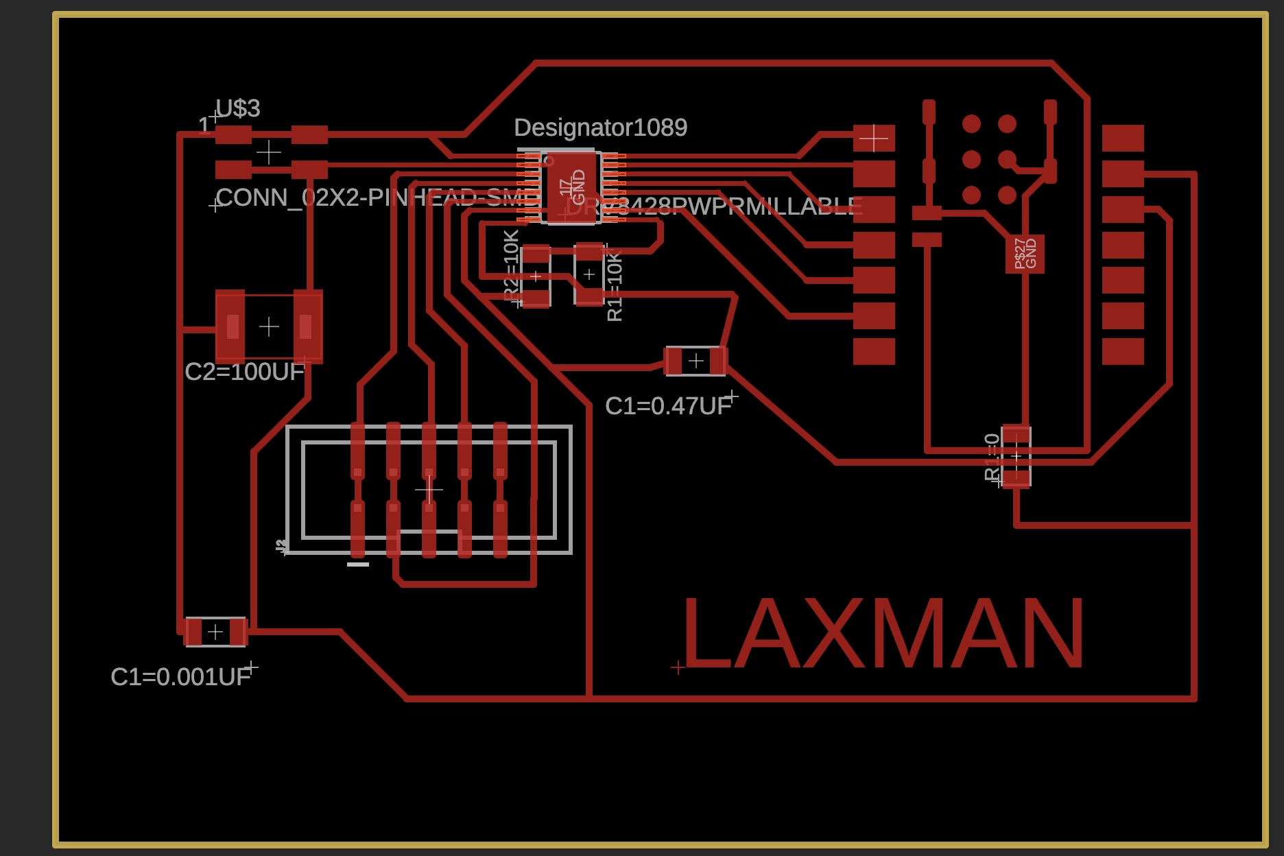
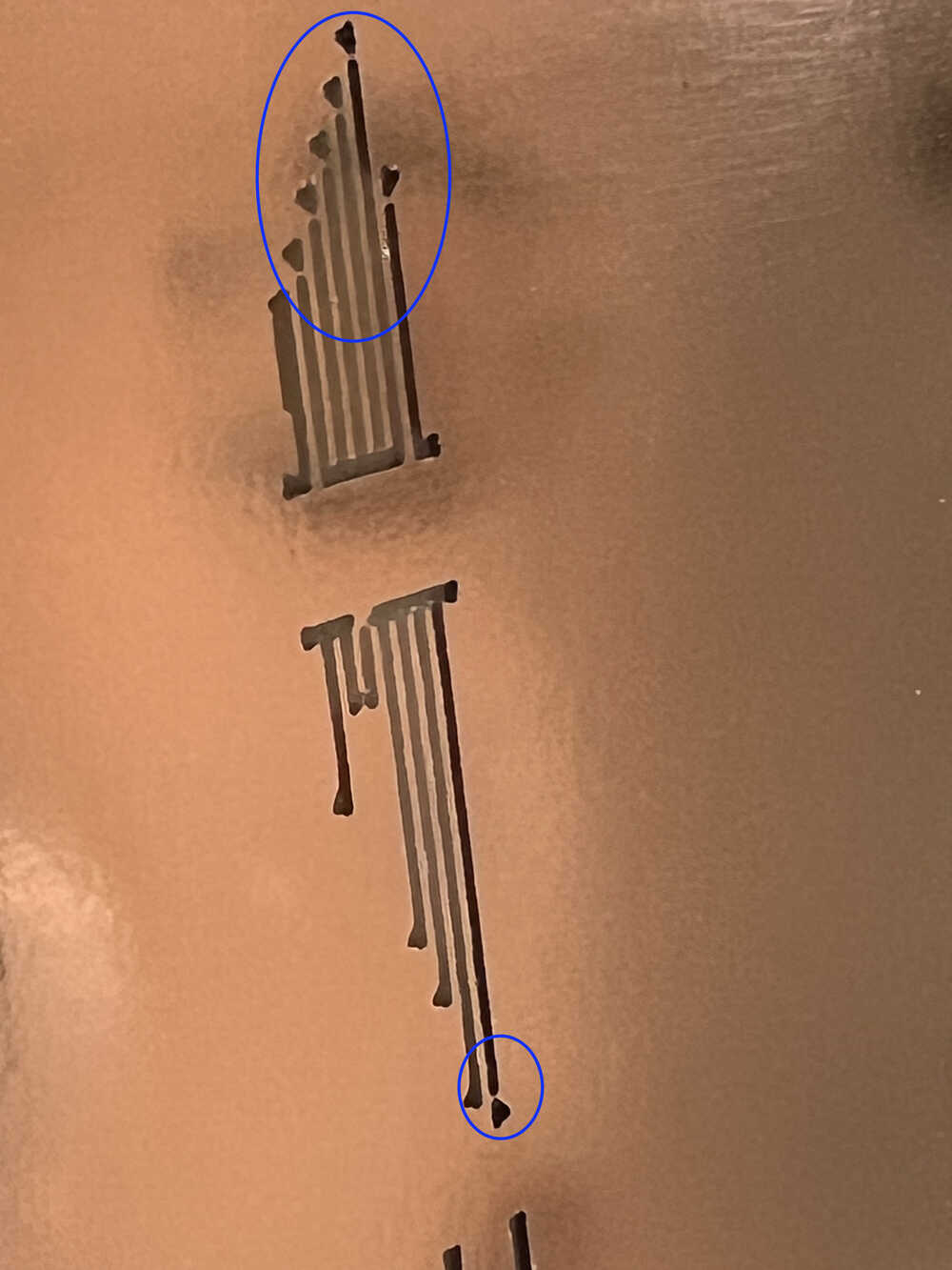
Before milling the board with the 1/64" and 1/32" end mills, Alec and I tested engraving bits to see if they could produce the smaller traces. After several trials, we found they weren’t reliable, so we went back to using the standard drill bits. You can see traces in the blue circle that need cleaning after milling, which can be done by simply cutting them with something sharp.
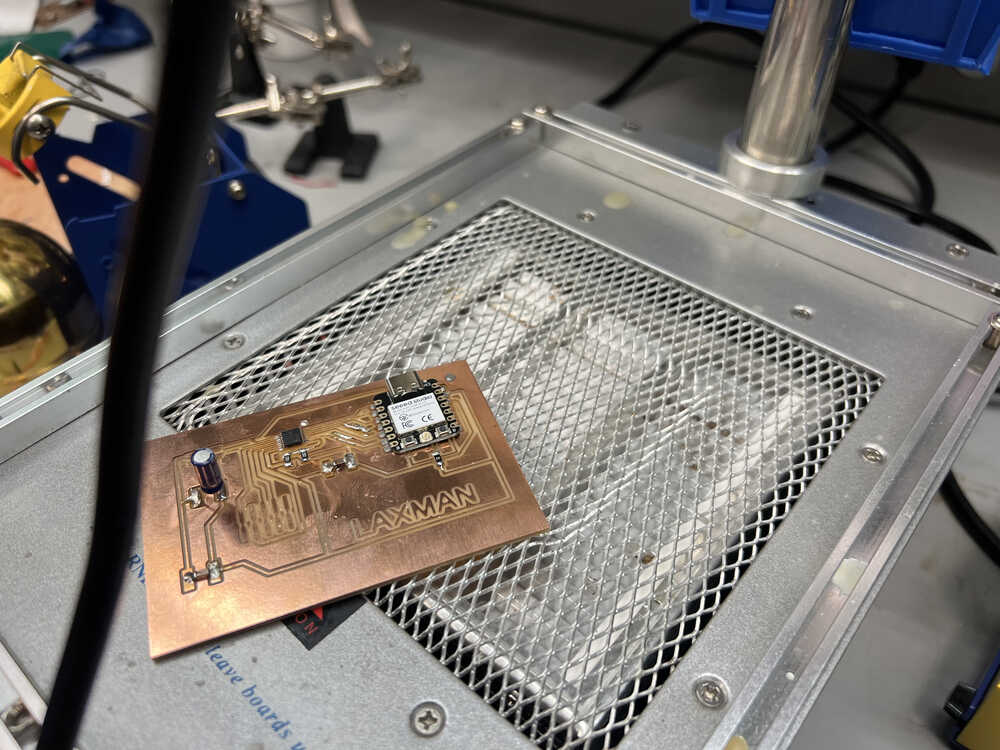
After milling, I hand-soldered components like capacitors and resistors. For the motor driver and the ESP32C3, I used reflow soldering. I applied hot air to the motor driver because its traces were exposed, but for the ESP32C3, which has power input pins on the underside, I used a heating plate.
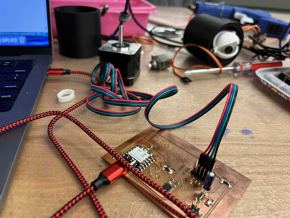
Once the board was complete, I began working on the code to run my stepper motor. Initially, it wasn’t working, so I spent some time troubleshooting. I used code from the class lecture notes.
Anthony suggested there might be a problem with the power connection, so I re-routed the motor’s power supply from 3V to 5V, and that solved it. Here’s a picture of the working board.
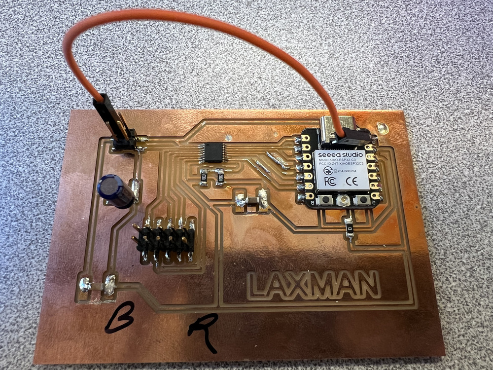
Here’s evidence that it’s working!