                            //Week 4 project electronic part
                            #include

                            Servo main_servo;

                            int pos = 0;
                            int i = 0;

                            void setup() {
                            Serial1.begin(115200);
                            main_servo.attach(0);
                            }

                            void loop() {
                            for (pos = 0; pos <= 180; pos +=1){
                                if (pos % 15 == 0 && pos != 0) {
                                // Backward rotation of 5 degrees
                                for (i = 0; i <= 5; i +=1){
                                    main_servo.write(pos-i);
                                    delay(50);
                                }
                                }
                                main_servo.write(pos);
                                delay(50);
                            }
                            for (pos = 180; pos >= 0; pos -=1){
                                if (pos % 15 == 0 && pos != 0) {
                                // Backward rotation of 5 degrees
                                for (i = 0; i <= 5; i +=1){
                                    main_servo.write(pos-i);
                                    delay(50);
                                }
                                }
                                main_servo.write(pos);
                                delay(50);
                            }
                            }
Week 4: 3D Scanning and Printing
This week, we kicked things off by starting the group project after the Tuesday night recitation. You can check it out here: Week 4: group project.
For the individual assignment this week, the task is to design and 3D print something that can't be made with subtractive methods, along with 3D scanning an object and printing it.
I started brainstorming ideas for something that couldn’t be created with subtractive methods. That’s when I noticed a ball bearing system lying around in the EECS lab. While the individual parts can be made subtractively and assembled, they can't be created as a single piece through subtractive manufacturing. This sparked the idea to design something like a turntable. I wanted to add a servo motor to rotate the turntable, with a platform to place objects for 3D scanning or other purposes—not entirely sure where this could be used yet, but it seemed interesting.
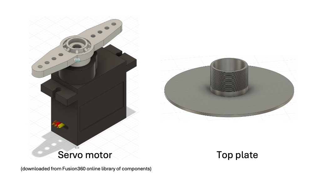
I didn’t just want to print this out as-is; I wanted to make it functional. So, I designed a platform for the servo motor that also holds the microcontroller driving the motor. On top of that, I needed a platform where I could place objects to be rotated.
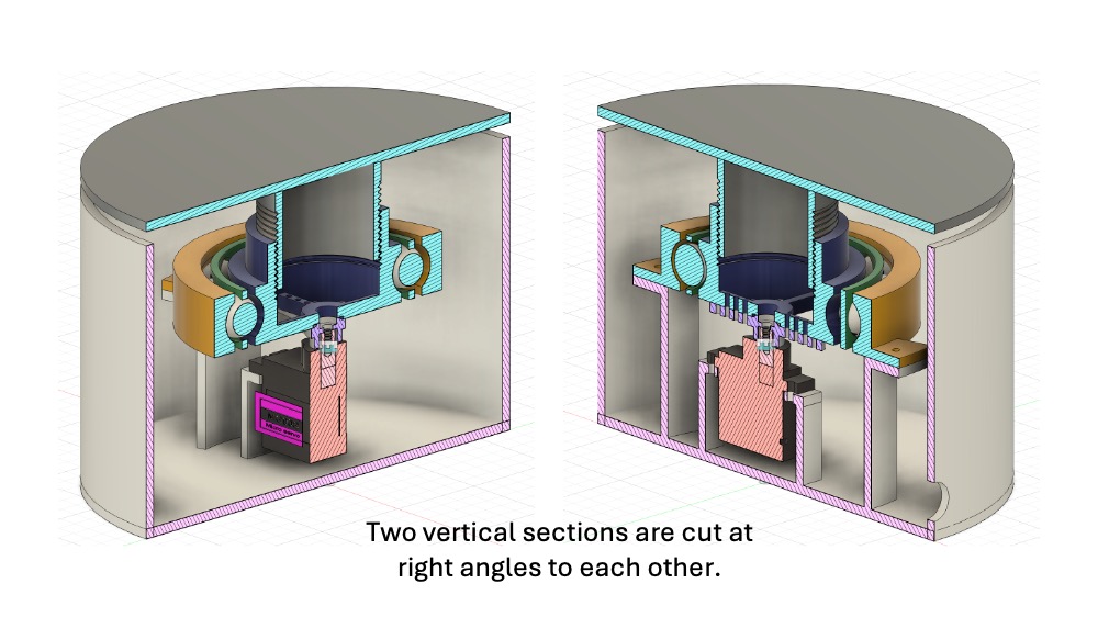
Once I finished the assembly and cut a vertical section, it looked like this:
Now starting the 3D printing
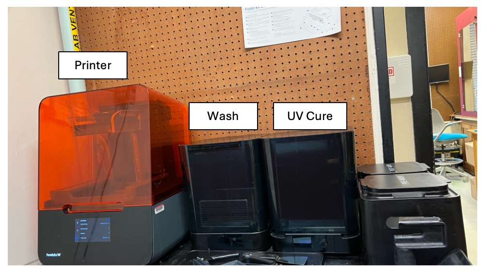
For printing, I checked out the 3D printer we have at the Einstein Rock Mechanics lab in Course 1. It’s an SLA printer from Formlabs—the Formlabs 3 model. SLA printers work differently from the Prusa printer we used for the group project, which is an FDM printer (also known as FFF). FDM printers melt filament layer by layer, while SLA printers use UV light to selectively cure resin, resulting in a much smoother surface and fewer visible layers. That’s why I chose the SLA printer for this project. As I write this, I’m waiting for the print to finish, hoping it goes well.
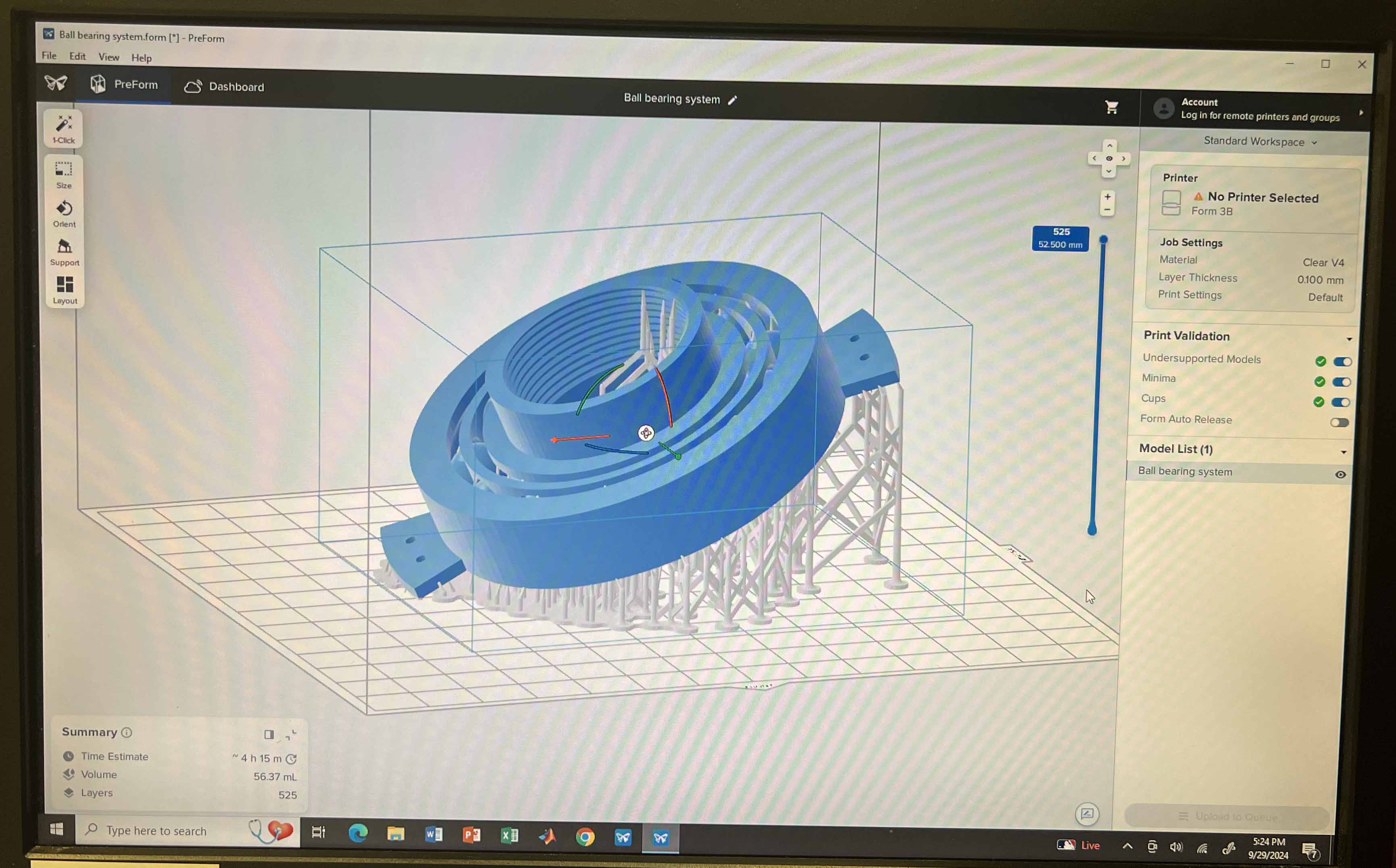
I started by installing PreForm on my computer, which has fewer options to tweak compared to the Prusa printer. I exported the mesh as an STL, opened it in PreForm to add the supports, and found out that there’s no option for infill in SLA printing. It can't print enclosed objects like filament printers can, but that wasn’t a problem for this design. After adding the supports, I saved the file as a .form file and sent it to the printer.
Figuring everything out on this printer was tricky, so I turned to YouTube for a tutorial, which helped walk me through the steps.
The printer estimated about 5 hours for the job, so I left it running overnight and came back the next day. As Neil mentioned in class, you should expect a few failed prints—and yep, mine didn’t turn out great. The spacing between the ball and bearing was too wide, and a few balls didn’t print at all. The middle bearing also didn’t connect correctly, so that was a full night’s print down the drain.
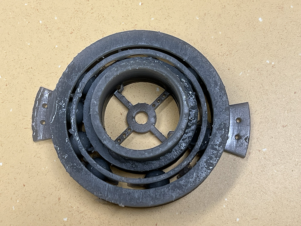
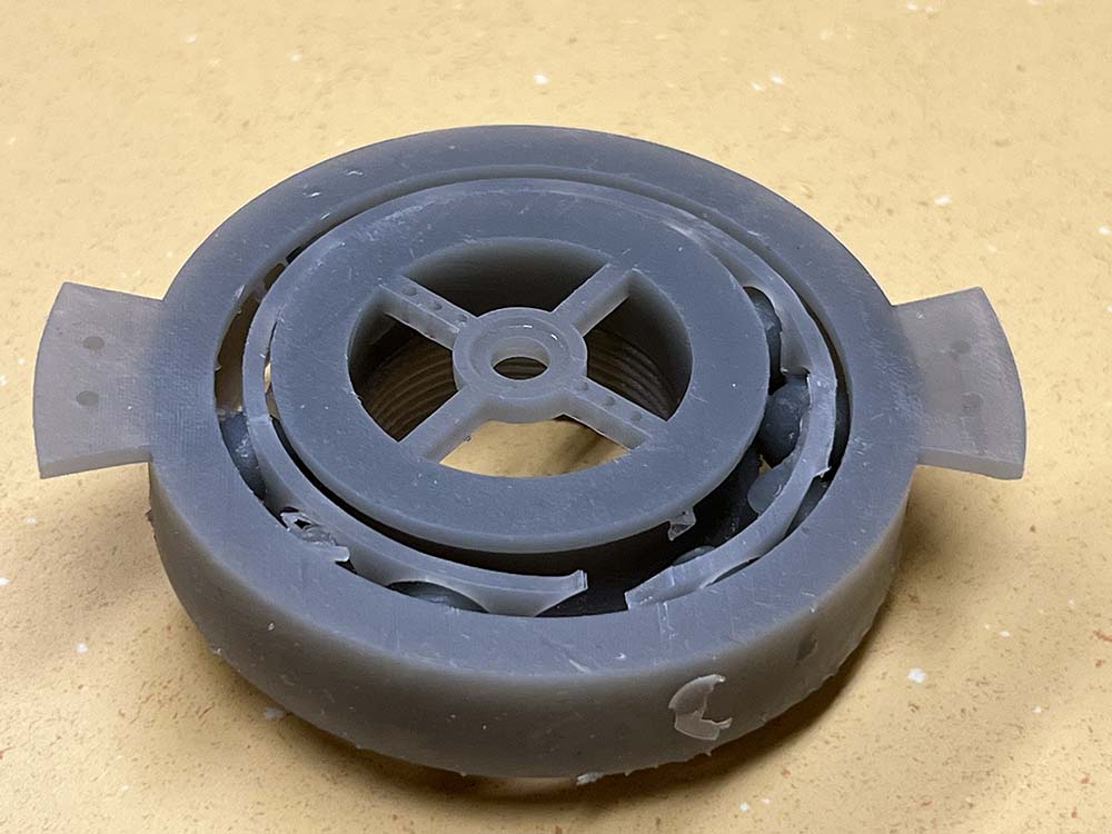
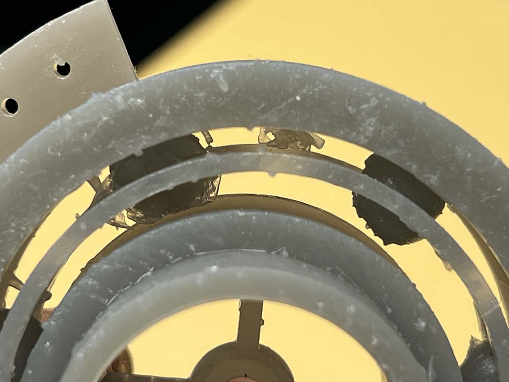
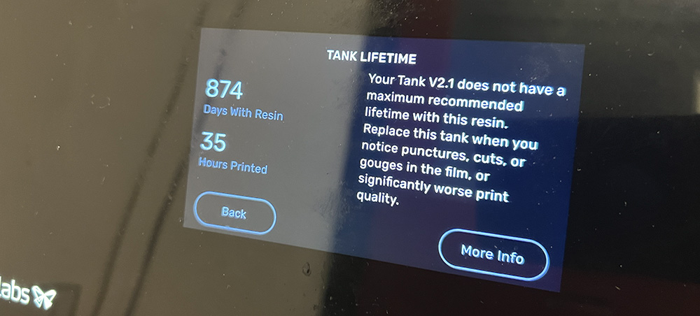
I think several factors contributed to the failed print. I noticed some solid resin chunks in the tray, likely leftovers from a previous print since the tray is old and the printer had been warning me about it. Another possible issue was using a medium mesh size when exporting the STL file from Fusion360. I’ll be changing these for the next attempt.
My second print attempt was submitted Sunday evening, and the printer said it would take about 8 hours. With the Formlabs SLA printer, it even takes an hour just to fill the tank with resin! I left the lab with everything seeming fine. When I came back in the morning, the printer had a problem with the resin cartridge—even though I had used a new one.
Lesson learned: Don’t leave the printer until it actually starts printing, and keep checking on it regularly.
The second attempt turned out better, but there were still issues with the ball-bearing system. Two spheres didn’t print fully, and the support inside the bearing system was tough to remove. After some effort with tweezers, I got it to rotate. There was also an issue with the screw system connecting the ball bearing to the top plate—both were the same size. Anthony suggested reducing the diameter on one side, so I did that and sent it for another print.
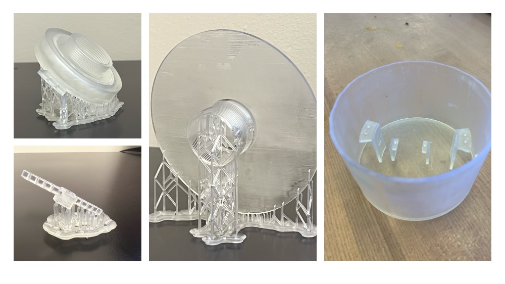
The ball-bearing system is now working fine (not quite though) after:
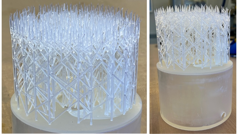
Even though there are still issues and room for improvement in the design, I decided to assemble it as is.
After putting it together, the servo motor struggled to rotate smoothly, so I modified the movement. Now it rotates 15 degrees forward, goes back 5 degrees, and repeats until it reaches 180 degrees, then it reverses. I’m hoping this back-and-forth motion will stop the ball bearing from jamming.
You can grab the CAD file for this project from here.
Project Improvements
If you want to recreate this project in the future, here are some improvements to make:
- Print the ball bearing system using a printer that supports soluble support material.
- The connection between the ball bearing system and the box doesn’t need to be a screw connection. You can restrain it from horizontal movement using several different connection types.
- For the connection between the ball bearing system and the top plate, you can use a slider connection. No need for screws here either—just make sure it’s only constrained in the rotation direction, leaving the other directions free.
- During the printing process, carefully monitor the design and check regularly for errors.
- Adjust the size of the holes connecting the motor arm and the ball bearing system, as the current design isn’t ideal.
3D scanning an object and printing
Another task this week was to scan something and optionally print it. Everyone’s first choice was to scan themselves and print a small version, and I wasn’t any different. Keeping up with tradition, I decided to scan myself. It wasn’t easy and required some help. Anthony helped me with the scan, and it turned out way better than we expected!
Then I decided I have to print small me.
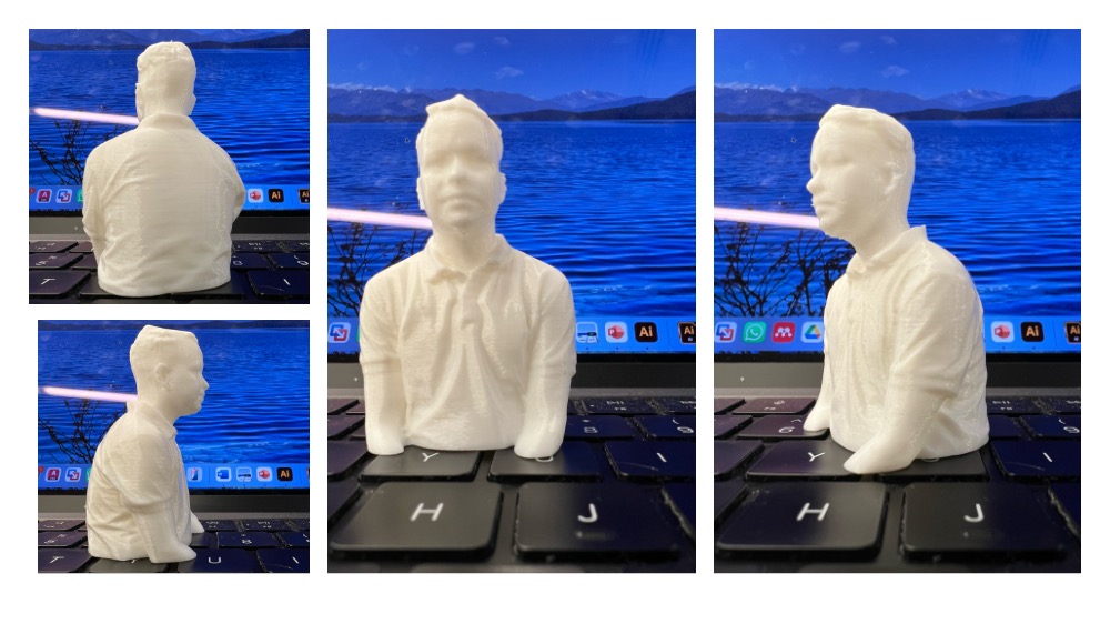
I have scanned several other objects using a mobile app called "Polycam" on my iPhone. However, the basic version of the app doesn't allow exporting 3D models. I was able to download the video.
1. Turntable and printer-produced support [Click here to see the 3D file]