Week 5: Electronics design
This week's assignment is to use an EDA tool to design a development board that interacts and communicates with an embedded microcontroller.
This is something I've never done before, so I'll be taking it step by step. We have several choices for which EDA design tool to use for this assignment. During the recitation hour, four introductory tools were presented: AutoCAD Fusion 360, KiCAD, SVG-PCB, and JSON-PCB. SVG-PCB and JSON-PCB are web-based EDA tools developed by one of our TAs, Quentin.
I am more familiar with AutoCAD, and everyone has been telling me that electronic design using Fusion 360 is easy to learn, so I've decided to use it for this week's assignment.
First, let's begin by reviewing the design rules that we need to modify. These rules aren't universal; they are specific constraints based on the equipment available in our section. Furthermore, I’ll be listing everything new or exciting I learn along the way. Which you can find that at the end of this page.

In Week 3, I built a traffic light system on a breadboard. To familiarize myself with the EDA tool, I’ll start by recreating that system on an electronic board. Afterward, I’ll design a development board for my final project.
Project 1: Traffic Light Signal
I expect this project to be relatively quick and straightforward. During it, I plan to apply what I’ve learned from the recitation and office hours. For this project, I’ll be using 10 1k resistors, one 10k resistor, a XIAO_RP2040, a 0 Ohm resistor, an SW switch, and 10 LEDs.
Schematic

PCB

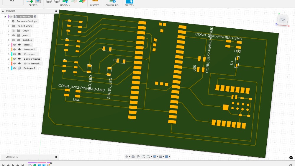
Rendered View


Exporting file for production
Gerber files are the standard, widely accepted format for exporting PCB designs to manufacturers. They're essentially 2D vector files that describe the different layers of your PCB. When I exported my files, Fusion 360 created three folders: Assembly, DrillFiles, and GerberFiles. The GerberFiles folder had the copper layout for both the top and bottom layers, along with other necessary details like the solder mask and solder paste info for the top and bottom. To export the Gerber files, just go to the Manufacture tab in Fusion 360 and follow the steps there.

Click here to download the file
Gerber to PNG
I used this online converter to convert my garber to PNG. The top cupper image look like this.

Profile

Project 2: Board for final project
Alright, let's break down what I need for the board for my final project. First, the board should be able to support Wi-Fi communication or direct message connection with a nearby computer that controls most of the tasks. It also needs to control four servo motors for eye movement and one larger servo to rotate the rock (though that part’s optional) for the rock toy. I’d also like an LED screen (now I am considering OLED screen) to display some messages and a few smaller LEDs to indicate power status or other simple info. On top of that, I want to connect a camera module (camera module can be directly connected to ESP32, so I am using that) to the board to track people and adjust the eye movement based on that. And finally, the board should connect to a speaker for audio output. That's what I have in mind so far.
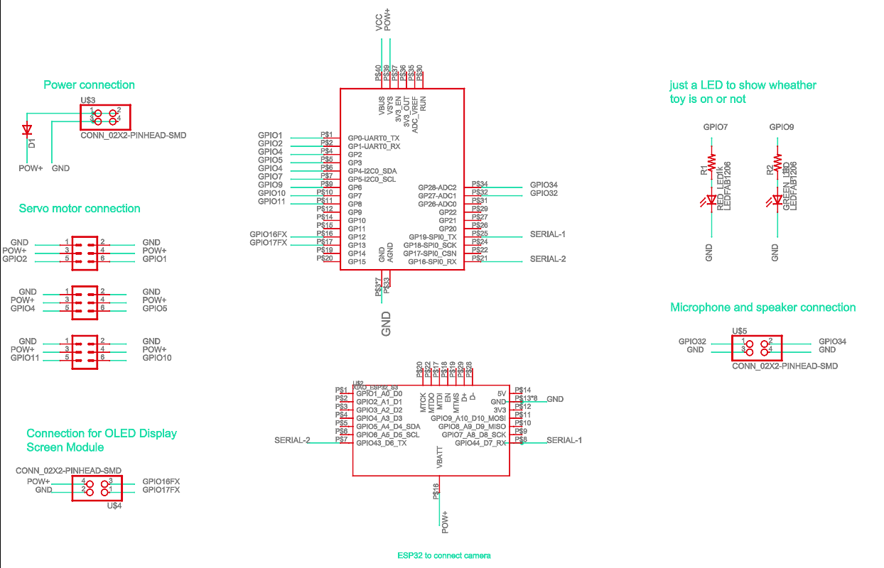
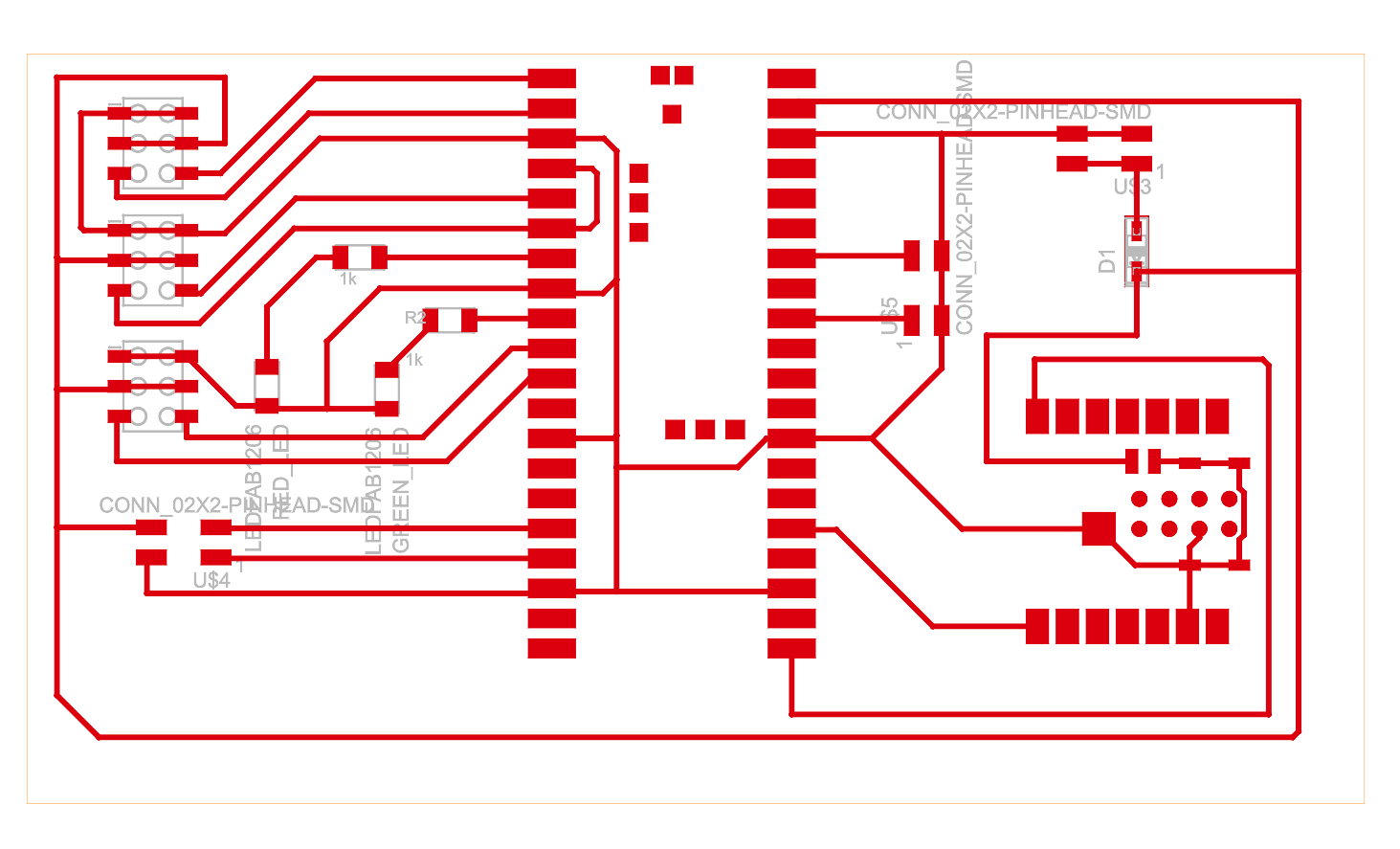
After several trials and errors, and consulting with Anthony and Sam, I finally came up with the version 0 (V0) of the board for my final project. There isn’t too much happening on the board—it's primarily designed to house a Raspberry Pi Pico and an ESP32, both of which have their own microcontrollers.
Since I need to use five servo motors, the power from the Raspberry Pi Pico alone won’t be enough. So, I decided to connect an external power supply. To prevent any potential damage from power connection errors in the future, I'm adding a diode to ensure the current flows in only one direction.
The Raspberry Pi Pico and the ESP32 are connected in series for communication between the two microcontrollers. I’m also adding a four-pin output connector for the OLED display, and another four-pin output for the microphone and speaker. Even though I don’t have immediate plans to use the microphone, it would be great to incorporate it as a sensor to detect people.
Schematic

PCB


KiCAD
I wanted to see what KiCAD is capable of. This seems smoother compared to Fusion360, but I am an AutoCAD guy and have experience with AutoCAD, which made me love Fusion360. Anyway, I gave KiCAD a try, and I ended up loving it. Before starting, I watched last year’s recitation video on KiCAD by Quentin.
I feel like the basic functions and workflow of both KiCAD and Fusion360 are almost the same. However, for someone like me, who is more familiar with AutoCAD and Fusion360, Fusion360 seems easier to use. I didn’t find the design rule window in KiCAD, so I didn’t use it for my work. Maybe because of that, it was letting me cross two lines over each other, something that I find Fusion360 handles more easily.
Schematic

PCB

How to export

Click here to download the Gerber files
Learning
- Design rules are important, and I like to adjust them when I start working on the project. FYI: you can only change the design rules when you switch to the PCB document.
- The "Name" command or the Name icon in the Fusion360 ribbon is really useful. You can use it to connect two points without actually wiring them by naming both wire ends the same. You can also use it to name components, which makes assembling them easier later in the PCB layout.
- Make sure to change the design rule if needed before starting to draw wiring for the board. You can change the design rule later, but using the change command is difficult in areas where new rules violate existing ones, and Fusion360 won’t let you change them easily.
- KiCAD is a great alternative to Fusion360. Since it doesn’t run on the cloud, it is much faster compared to Fusion360.
- If you want to design a board but don’t know where to start, always check the websites of the parts or components you plan to use. Read the documentation to find out how many connection ports you need and what types of ports are required.
- When exporting a file for production, the most popular format is Gerber, which you can export from both Fusion360 and KiCAD, as well as most other EDA tools. Nowadays, there’s no need to convert Gerber files to PNG, but if you do, there are plenty of free online tools for that.
- Using a zero-ohm resistor is a good solution to avoid copper lines crossing each other. This is useful if your board only needs one or two crossings and you don’t want to create a two-layer board. If you need multiple crossings, making a double-layer board is a wiser choice.