                            //Traffic light 1
                            #define RED_T1 26
                            #define YELLOW_T1 27
                            #define GREEN_T1 28
                            #define BLUE_T1 29

                            //Traffic light 4
                            #define RED_T4 1
                            #define YELLOW_T4 2
                            #define GREEN_T4 4
                            #define BLUE_T4 3

                            //Pedestrian P1
                            #define RED_P1 7
                            #define WHITE_P1 0
                            #define switch_1 6

                            //defining variables
                            int num;
                            int i;
                            int val = 0;
                            int oldValue = LOW;


                            void setup() {
                            // Traffic light 1
                            pinMode(RED_T1, OUTPUT);
                            pinMode(YELLOW_T1, OUTPUT);
                            pinMode(GREEN_T1, OUTPUT);
                            pinMode(BLUE_T1, OUTPUT);

                            // Traffic light 4
                            pinMode(RED_T4, OUTPUT);
                            pinMode(YELLOW_T4, OUTPUT);
                            pinMode(GREEN_T4, OUTPUT);
                            pinMode(BLUE_T4, OUTPUT);

                            // Pedestrian P1
                            pinMode(RED_P1, OUTPUT);
                            pinMode(WHITE_P1, OUTPUT);
                            pinMode(switch_1, INPUT);
                            }

                            void delay_1(int num) {
                            for (int i = 0; i < num; i++) {
                                int newValue = digitalRead(switch_1);
                                if(newValue != oldValue) {
                                val = 1;
                                }
                                printf("%d",val);
                                delay(10);
                            }
                            }
                            void traffic_cycle(){
                            digitalWrite(RED_T1, LOW);
                            digitalWrite(GREEN_T1, HIGH);
                            delay_1(2000);

                            digitalWrite(GREEN_T1, LOW);
                            digitalWrite(BLUE_T1, HIGH);
                            delay_1(1000);

                            digitalWrite(BLUE_T1, LOW);
                            digitalWrite(YELLOW_T1, HIGH);
                            delay_1(300);

                            digitalWrite(YELLOW_T1, LOW);
                            digitalWrite(RED_T1, HIGH);
                            delay_1(100);

                            digitalWrite(RED_T4, LOW);
                            digitalWrite(GREEN_T4, HIGH);
                            delay_1(2000);

                            digitalWrite(GREEN_T4, LOW);
                            digitalWrite(BLUE_T4, HIGH);
                            delay_1(1000);

                            digitalWrite(BLUE_T4, LOW);
                            digitalWrite(YELLOW_T4, HIGH);
                            delay_1(300);

                            digitalWrite(YELLOW_T4, LOW);
                            digitalWrite(RED_T4, HIGH);
                            delay_1(100);
                            }

                            void pedestrian(){
                            digitalWrite(RED_P1, LOW);
                            digitalWrite(WHITE_P1, HIGH);
                            delay_1(1000);

                            digitalWrite(WHITE_P1, LOW);
                            digitalWrite(RED_P1, HIGH);
                            delay_1(100);
                            val = 0;
                            }

                            int main(){
                            setup();
                            digitalWrite(RED_T1, HIGH);
                            digitalWrite(RED_T4, HIGH);
                            digitalWrite(RED_P1, HIGH);

                            while(true){
                                traffic_cycle();
                                //check if pedestrian button is pressed or not?
                                if(val == 1){
                                pedestrian();
                                }
                            }
                            return 0;
                            }
Week 6: Electronics production
This week's individual assignment was to make and test a microcontroller development board that was designed last week. The goal was to use one milling process, and if time allowed, to try another one. Most of the time, I really tried to stick to my schedule, but this week turned out to be an exception.
I dedicated most of Tuesday to working on my final project. My first milestone is to design and test an eye mechanism. Once that’s done, I'll start on the rock carving portion, this is because I first need to decide the size of the holes required to house the eyes. You can go to my final project webpage to see my latest eye mechanism desing. I am planning to 3D print this and test it this week.
The work for this week started on Thursday after the recitation, when Anthony explained how to operate the Bantam Tools desktop PCB milling machine. It seemed straightforward, especially for milling a small board.
Saturday was the biggest festival in my country, so I couldn’t work on the assignment that day either. Now it’s Sunday, and as I write this, I’m getting ready to start my week 6 assignment.
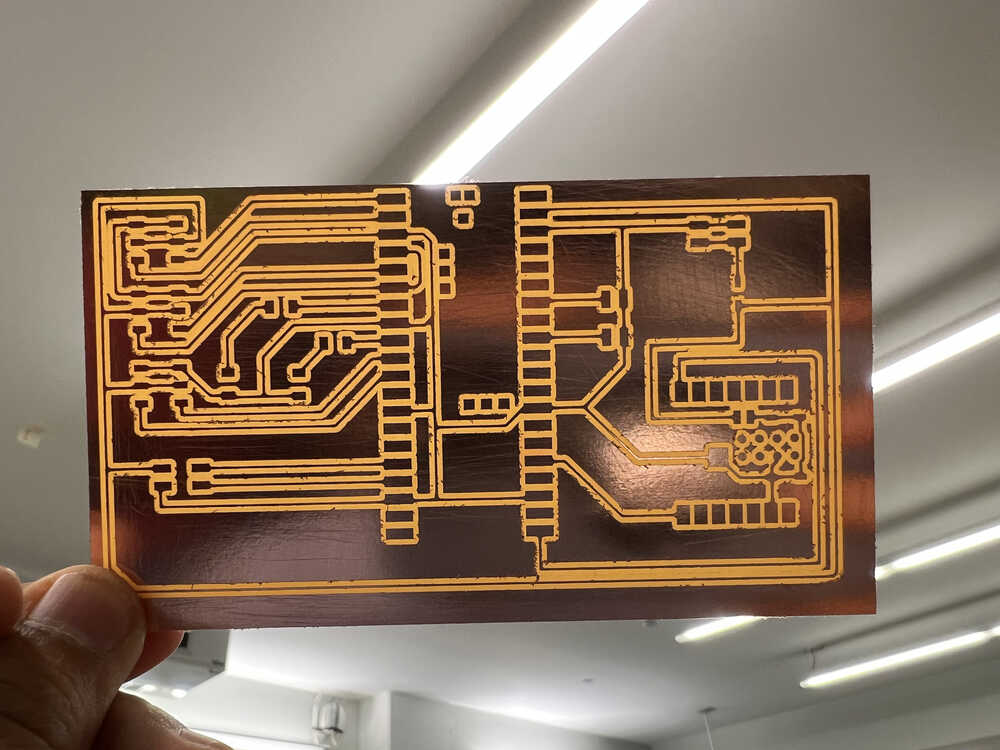
I designed two circuit boards in Week 5: one for the traffic light system and the other for my final project. I started by milling both boards using the Bantam milling machine. When they came out of the machine, the edges were rough, but after some gentle sanding with sandpaper, they looked pristine.
Despite the sanding, there were still some hair-like dust particles left from the milling process, likely due to a dull milling tool. I removed these by running a sharp object through the cut portions.
1. Traffic Light Board
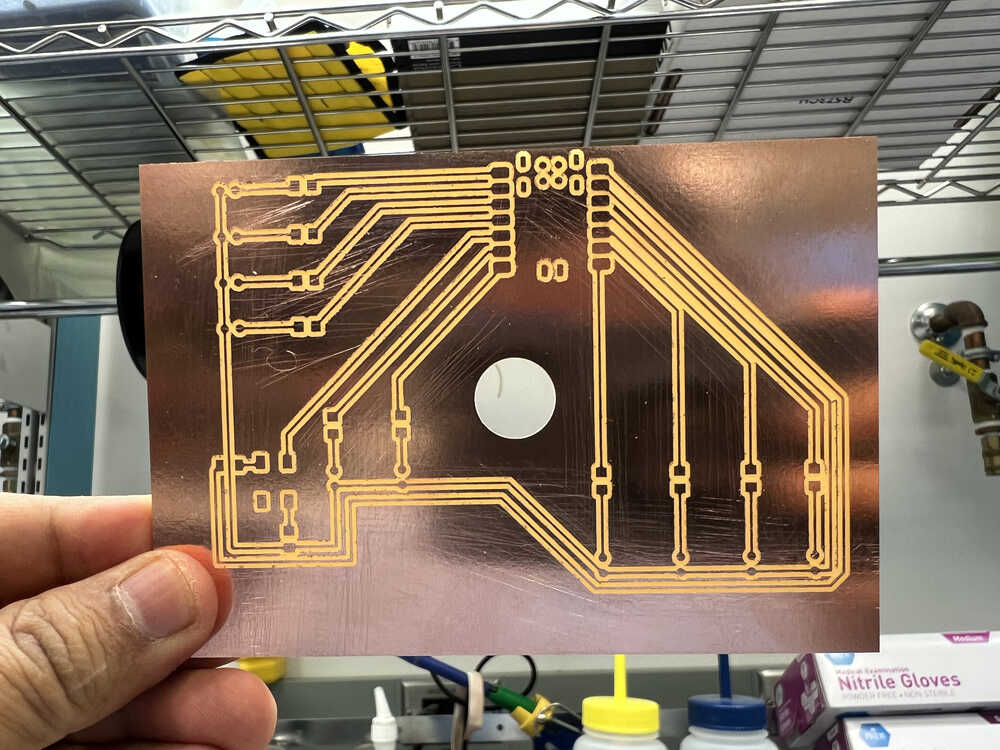
Our task isn't just to print the circuit boards but also to assemble them by soldering the components onto the board, which has been the most challenging part for me. I've never soldered before, but it's a skill I've always wanted to learn. I started with the traffic light circuit board since it was simpler, featuring only one microcontroller and some small components.
My first attempt was soldering the Xiao RP2040 to the board, and it went pretty well for a first try.
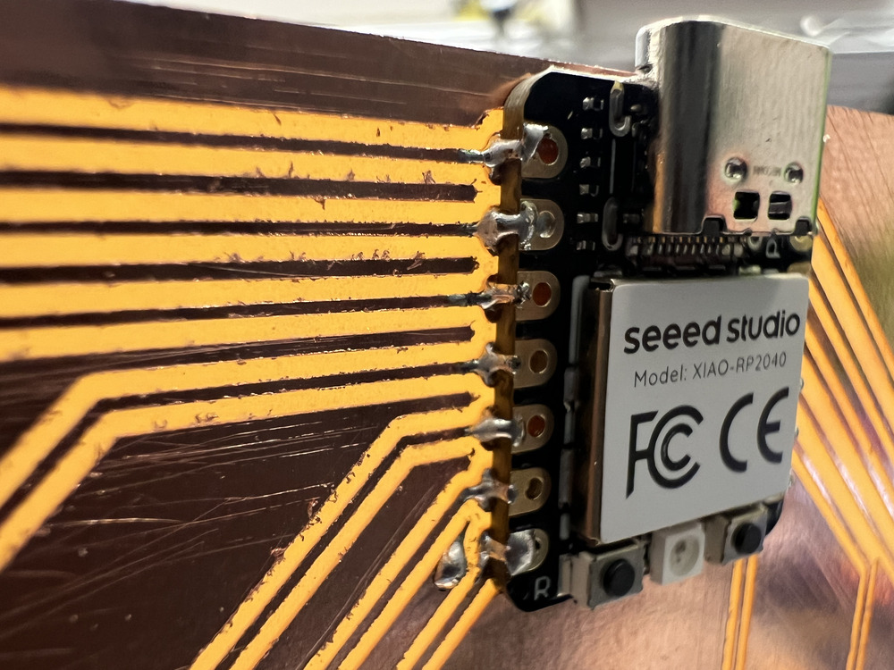
I checked the connections using a multimeter to ensure everything was working correctly. After that, I soldered the resistors onto the board, and that process went smoothly as well.
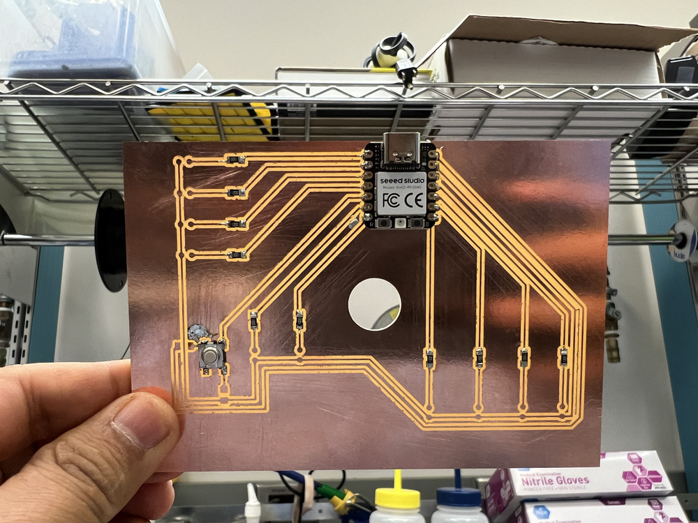
I did, however, make a bit of a mess while soldering the toggle switch, but I used a desoldering braid to clean it up. The trick with using the desoldering braid is to place it on the excess solder and then apply the soldering iron on top. The heat transfers the excess solder into the copper braid.
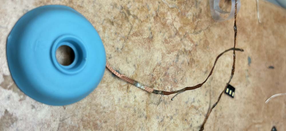
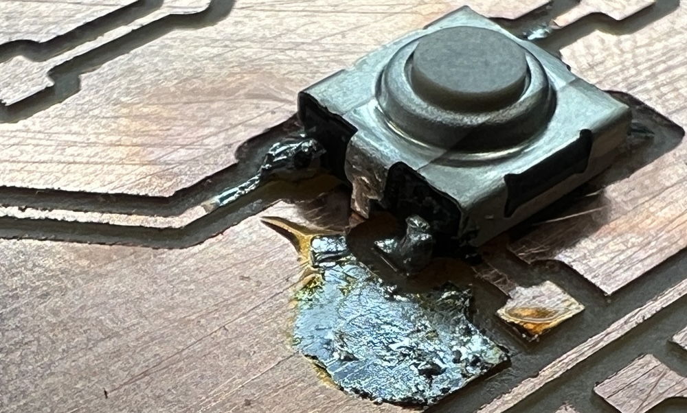
It was a learning experience and an opportunity to use different tools. Unfortunately, while soldering the LED light, I accidentally damaged the copper traces, making the board unusable. I attempted various fixes, but in the end, I decided it would be quicker to create a new board than spend more time troubleshooting this one.
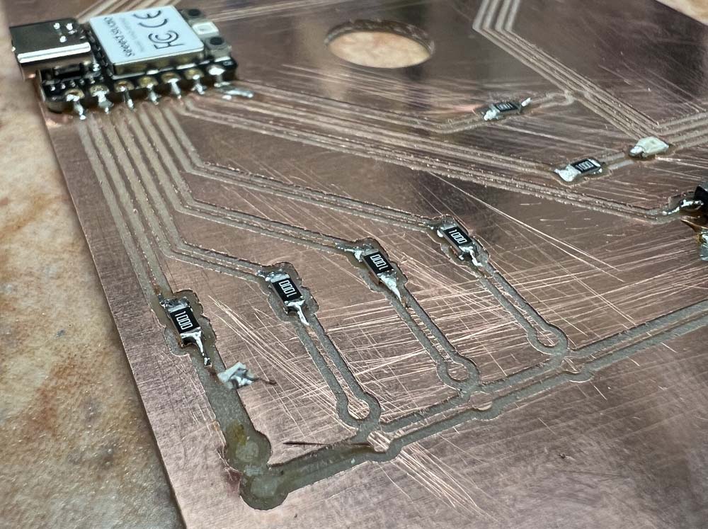
For the new board, I also switched to a different type of LED pin, which made the process easier. You can see this change in the new board below.
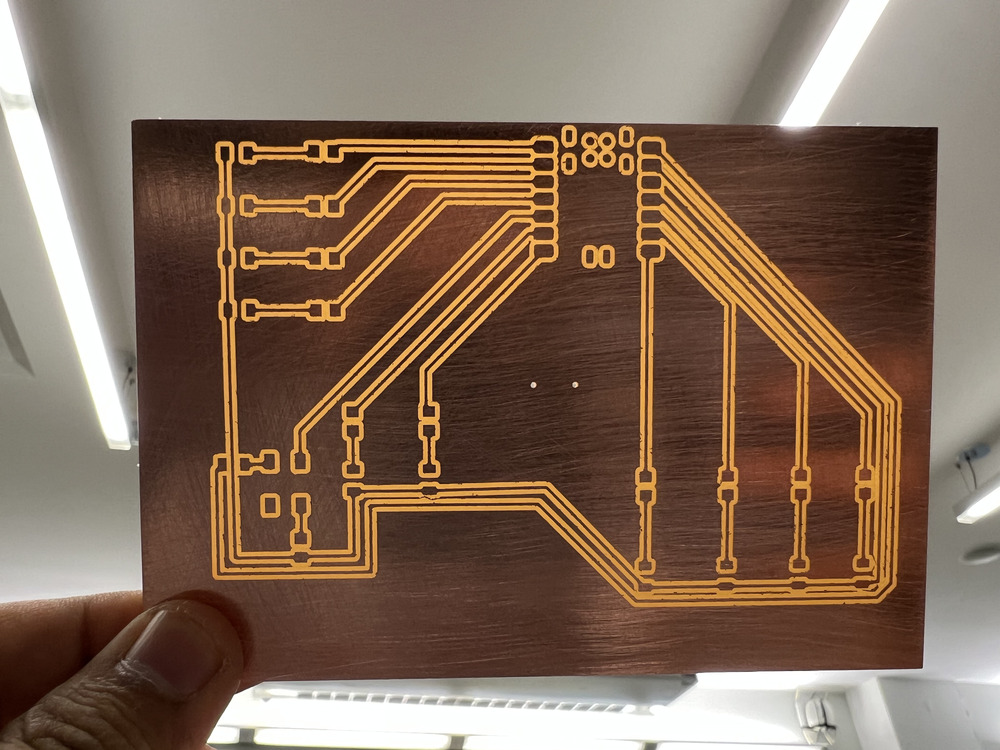
Soldering was tricky at first, but after several attempts and some guidance from the TAs, I can now make a solid solder joint. I successfully soldered the new traffic light board that I had prepared.
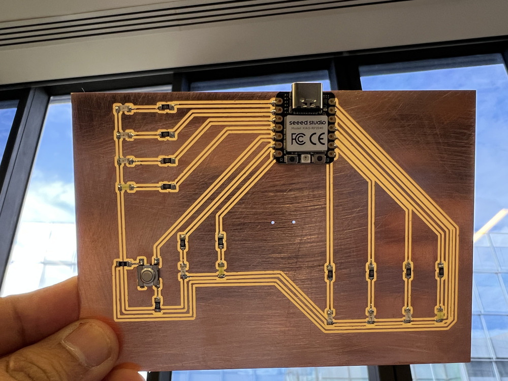
Afterward, I rewrote the traffic light code I originally developed for the Raspberry Pi Pico to work with the Xiao RP2040.
2. Board for the final project
I designed this board last week as well. It primarily houses a few LED lights to indicate whether the board is functioning, and it includes two microcontrollers: the Raspberry Pi Pico and the Xiao ESP32. The Raspberry Pi Pico is used to control the servo motors and connects to the microphone and speaker sensors. The ESP32 is mainly responsible for the camera module and its built-in Wi-Fi. The ESP32 will handle the video sensor and communicate with the Raspberry Pi to move the eye mechanism accordingly. This is the plan for now—let’s see how much I can achieve.
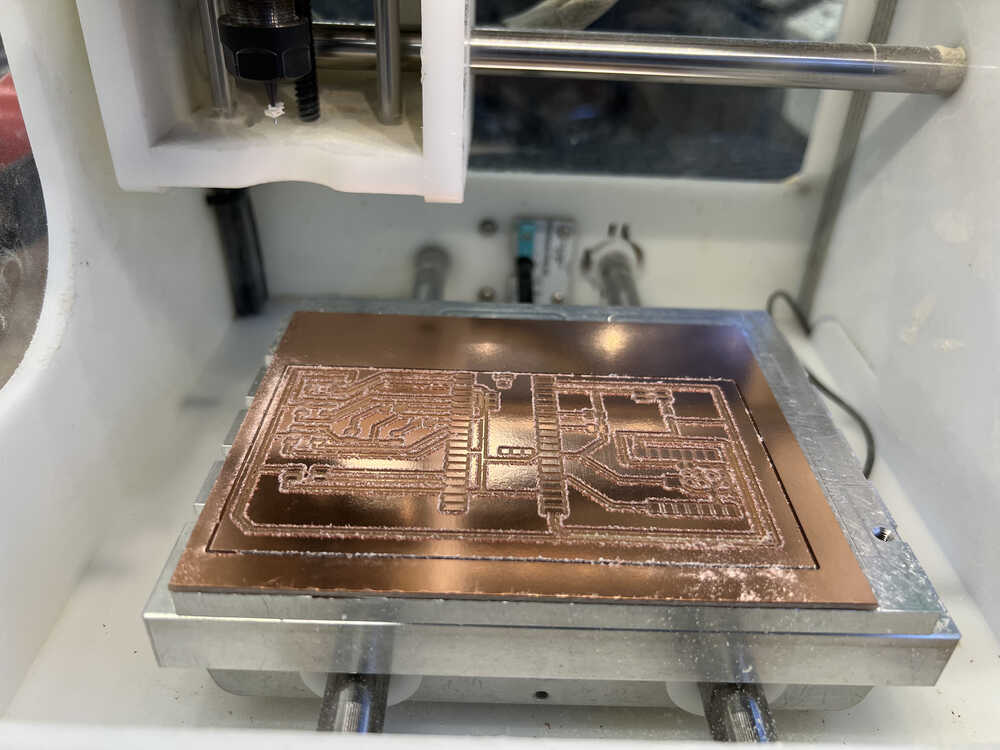
1. Fresh after milling:
2. After slight sanding:
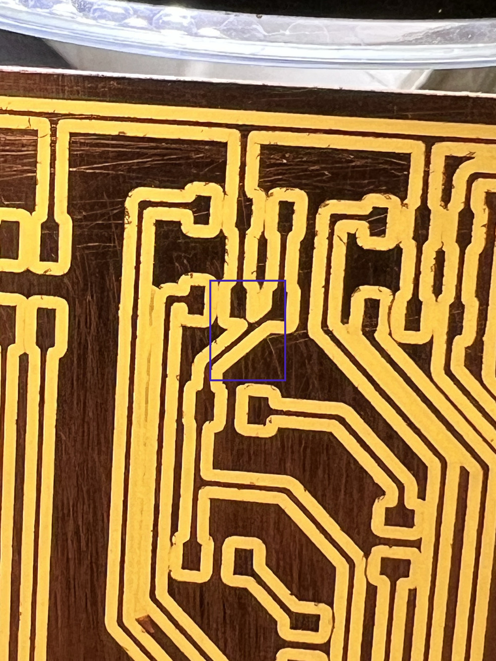
3. Though inspection
There was an unintended connection between the ground wire and the power due to an imperfect milling process, as shown in the picture below within the blue square. I resolved this by running a sharp object through the milling path.
4. After soldering
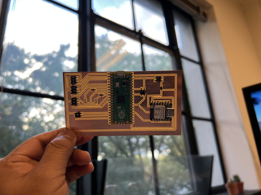
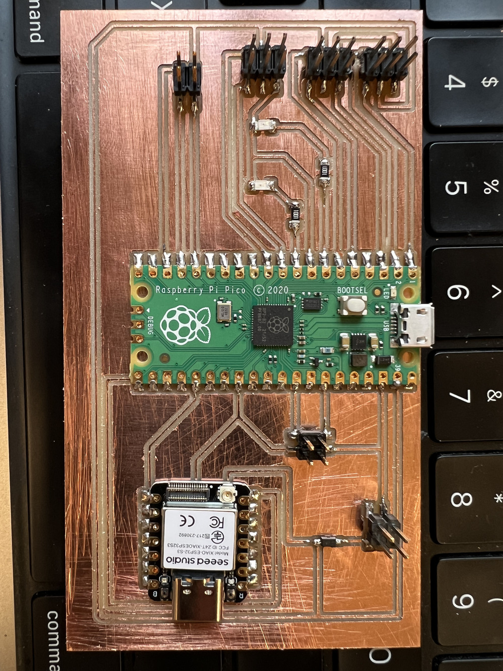
I am still not completely satisfied with my final board design, but I will use it to test the eye mechanism I've prepared for the final project. I'll continue updating the board as I work toward the final version.