
We had a group session with our TA Quentin and discussed some microcontroller options:
AVR 8 (8 bit) vs ARM32 (32 bit)- have different pros and cons; require different communication protocols
AVR 8-
ATTiny - great for many things but doesn’t have a lot of memory; larger microcontrollers are often overkill but people don’t use ATTiny much any more because it doesn’t have a programmer built in. Great for simple projects- reliable and lower power consumption.
ARM 32-
SAMD, RP2040, ESP32 are different microcontrollers which can be found in a variety of boards that make different pins accessible. They can handle more complicated projects than the ATTiny. The SAMD is helpful for its USB capability and works well for low-power applications. The RP2040 is well documented, easy to work with, and can handle a lot of complexity. ESP32s are the best option for projects which require wireless communication.
RP2040 and ESP32 have enough processor power to use with micropython.
I decided to use an ESP32 because I know I want my final project to communicate wirelessly (specifially, sending sensor data to Max/MSP, where I plan to program my instrument). I have used a handful of different ESP32 boards before so thankfully I am already comfortable programming them and have done so in Arduino IDE and VS Code, using C, C++, and Assembly. My preferred method (and what I will use for this assignment and eventually my project) is Arduino IDE because I really like the workflow for installing and working with existing libraries. I also have already installed and worked with specific libraries that will be very helpful here, specifically this OSC library from CNMAT which allows you to send OSC (open sound control) messages from the microcontroller-- a very helpful tool when working with musical instrument interface design! I also already have my own skeleton code for using that library to send messages to Max/MSP over wifi.
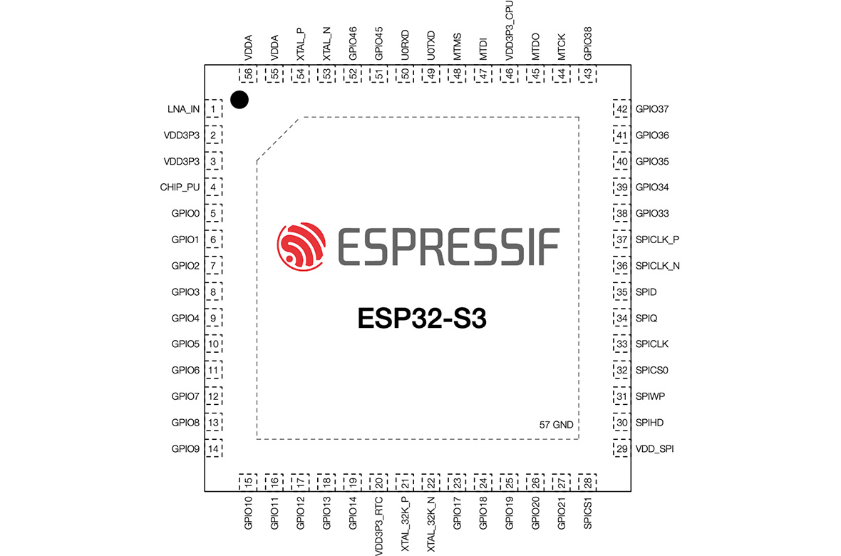
There are a few different ESP32 chips available; I will be using the S3 because it has a lot of ADC pins and I will need that since I plan to use a lot of flex sensors. Here are some features of the chip which I got through reading the datasheet:
- 2.4 GHz Wifi and Bluetooth
- 32 bit microprocessor
- SPI, I2C, and UART interfaces
- USB serial communication
- Built-in LED PWM controller (up to 8 channels- I have used it before and it's super helpful!)
- Motor Control PWM
- Remote Comtrol Peripheral (RMT)
- Temperature and touch sensors
- 3.3v input, 3.3 and 5v output pins
- Up to 20 channels ADC (10 ADC1 and 10 ADC2; ADC2 can't be used at the same time as wifi and some pins have other restrictions)
Making note of the pin layout and overview as that will be super helpful when it comes time to mill my own board, and in the meantime knowing which pins to use for what.


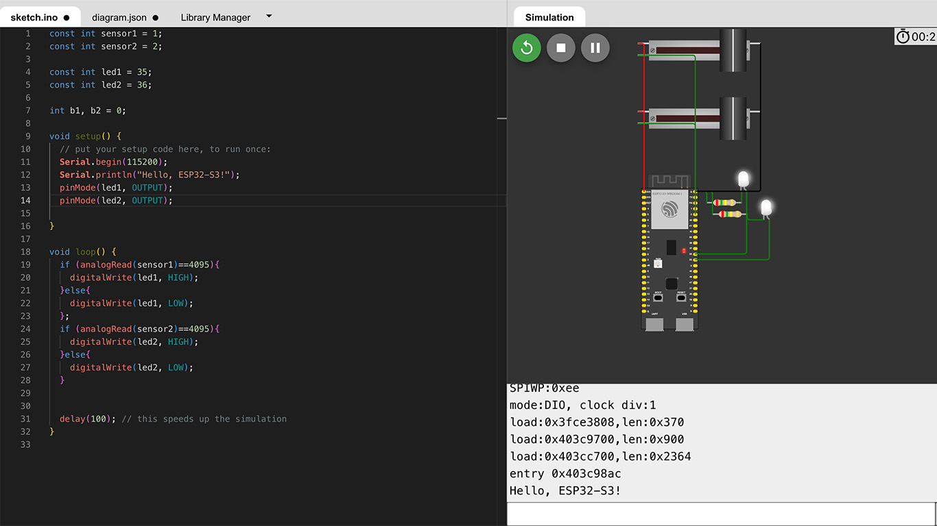
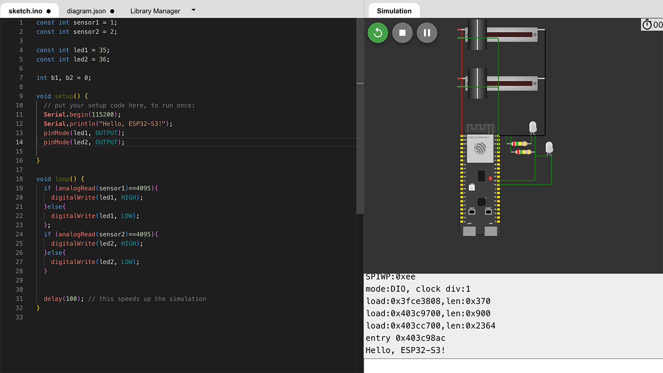
Testing out a super simple analog read on GPIO 1 and 2(both are ADC1 pins) to turn LEDs on and off using Wokwi, the simulation tool we were shown in class.


That was cute. Now time to go dig up the flex sensors that are in a box somewhere in my basement! (NOTE: The above stuff is my actual assignment for the week- the below is just playing with scraps of things I have made before so I am not bothering to document it as well.)
After digging arount in my basement I returned with a mixed collection of things including:
- ESP32S3-M1 devkit board
- some flex sensors
- LSM9DS1 IMU sensor from adafruit
- a breadboard and other things needed to assemble it all...
Code-wise, I am using the following libraries: Sparkfun LSM9DS1 (because it is much easier to work with than the adafruit one in my opinion), CNMAT OSC (mentioned above), Wifi, and Wire (for I2C communication with
the LSM9DS1).
With these things, I stitched together some new code and some chunks from past projects (which were stitched together with the assistance of library example code and internet tutorials) to send flex sensor and IMU data to a silly little noisy patch in Max/MSP. For wifi-- doing these things over MIT wifi is a pain so I normally use my own router but right now
I am at home so I'm just going to use my home wifi. Here is my breadboard setup (using a voltage divider circuit for the flex sensors)
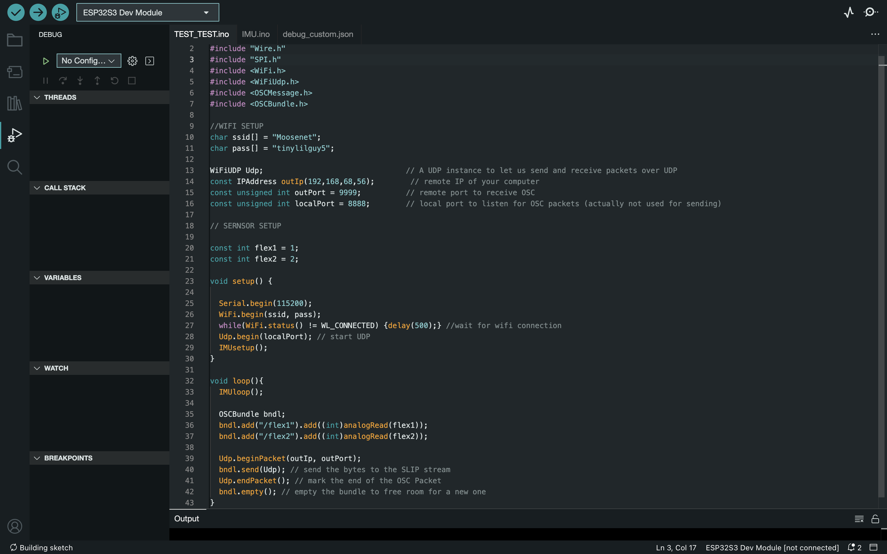
and the main portion of my code (IMU data is being read and sent in a different file and that is something i pretty much copied from the sparkfun tutorial but added in the OSC messages)


And here is a video of my useless but mildly amusing creation in action (this is a really shitty demo but I needed to keep the clip short for file size limits and filming with one hand while moving the sensors with the other and not disturbing my sleeping dog was challenging)
-- Wokwi file