
This week's group assignment: use the test equipment in your lab to observe the operation
of a microcontroller circuit board.
We met with Quentin in the shop and he gave us a demo using the multimeter and oscilliscope and provided some helpful debugging tips.

The assignment is: use an EDA tool to design a development board to interact and communicate with an embedded microcontroller.
The goal of this is to make something which will help us towards our final project.
Initially i was planning on doing my whole project with an ESP32s3-M1 devkit from espressif because the xiao board didn't have the number of pins I needed but now I'm realizing that using 2 xiaos will work and will make my life way easier. So here is what I will need:
- 4x paired 3.3v and ADC inputs with voltage divider circuits connecting to GND (I don't know the exact resistor value I need yet)
- SDA, SCL (GPIO), 3.3v and GND for the IMU
- 4x GND + 4x GPIO for LEDs control
Here is the schematic I made in KiCad:

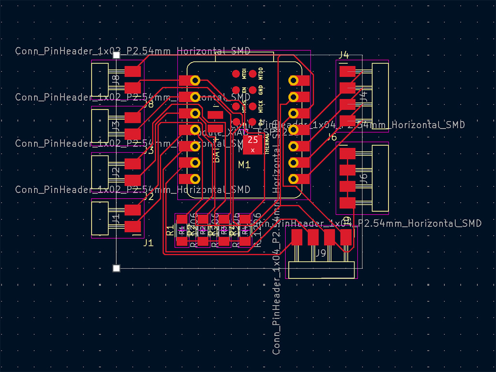
After finishing the schematic, I opened the PCB editor and spent a while tooling around with the placement until I liked where things were. To make this work, the routing needed to be much more complex then you might expect. Once done with that I exported as a black and white SVG.

