Week of Oct 23 2024
Add a sensor to a self-designed microcontroller board and read it
I did the following this week:
- Attended a fascinating demo by TA Anthony on soldering tiny things under a microscope
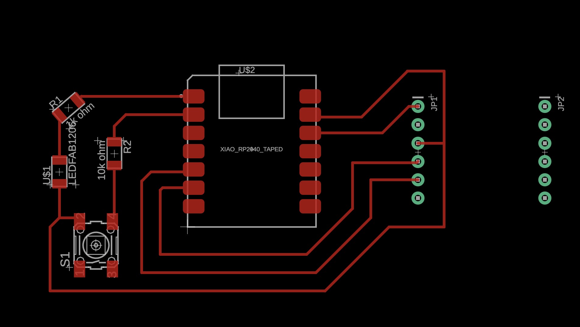
- Redesign PCB in Fusion Eagle (design file here)

Schematic view of new PCB - refined with larger solder pads, correct connections between the microcontroller and IMU based on specific components' pinouts, and more spacing between solder pads. 
PCB view in Fusion Eagle. - Mill redesigned PCB
- Connect IMU to microcontroller (breadboard style) and read it (via Arduino IDE)
- Solder connectors to new PCB and connect IMU and microcontroller. Tried solder paste!

The Adafruit BNO085 has 6 pins on each side, while the SEEED XIAO RP2040 has 7 pins on each side. There aren't 6 or 7 pin flat connectors available in the workshop, so I combined what was available: 5+2, and 3+3. 
Solder paste dispensed with a syringe. Used lead-free solder paste for now, but am cognizant that lead-free solder paste tends to have 'silver whiskers' once taken into space/ outside of Earth's gravity, which may be an issue for my final project. TA Anthony advised to search for alloys that does not contain silver. Maybe tin-bismuth? 
Heat gun set-up. 
PCB assembled with microcontroller and IMU through plug and play connectors! Will solder on the little components (switch, LED, resistors) another time...
Side note: Credit goes to TA Anthony for his patient, clear and engaging guidance on Fusion Eagle, soldering techniques, and general electronics expertise! I am convinced HTMAA actually stands for How To Make Anything with Anthony.
For all my electronics assignments I've found the search function on the class page immensely useful, so from now on I will also endeavor to document in a way that makes it easy for future coursemates to troubleshoot. Predecessors' pages that I've found useful for this week included the project sites of Zhixing (informed my choice to use I2C over UART) and Simon.
Things that went wrong and corresponding troubleshooting solutions, as well as general tips/ reminders:
- Issue: Component not found in Eagle library
- Solution (proper): download the ecad model from Digikey (select 'Autodesk Fusion' as the format); my specific requested component was here; follow the 'how to import' guide in the zip file.
- Solution (interim hack, if ecad model cannot be easily found): download whatever footprint information you can find online of the component. With an .sch file you can open it in Fusion Eagle and copy it into a schematic. If all else fails, approximate the pin-out based on known dimensions (e.g. from the datasheet of the component) and edit it in any raster editing software like GIMP or Photoshop, and save as PNG.
- Fusion Eagle: Option+Command+P to open up hidden "Data Panel" and delete/manage files; or hit the 3x3 grid icon on the top left that pops up "Data Panel".
- Issue: PCB mill unresponsive (Roland SRM-20).
- Solution: Click on terminal icon with wireless symbol (instead of terminal symbol) and type in "sudo chmod a+rwx /dev/usb/lp0 (or lp1 or whichever port it is connected to)" (see archshops tutorial to reconnect).
- Close lid to stop blinking green light; turn on and off to restart if blinking persists.
- Always have inverted colors for trace mill! When in doubt, scrutinize the mill path after 'calculate' to check that you are cutting the right parts.
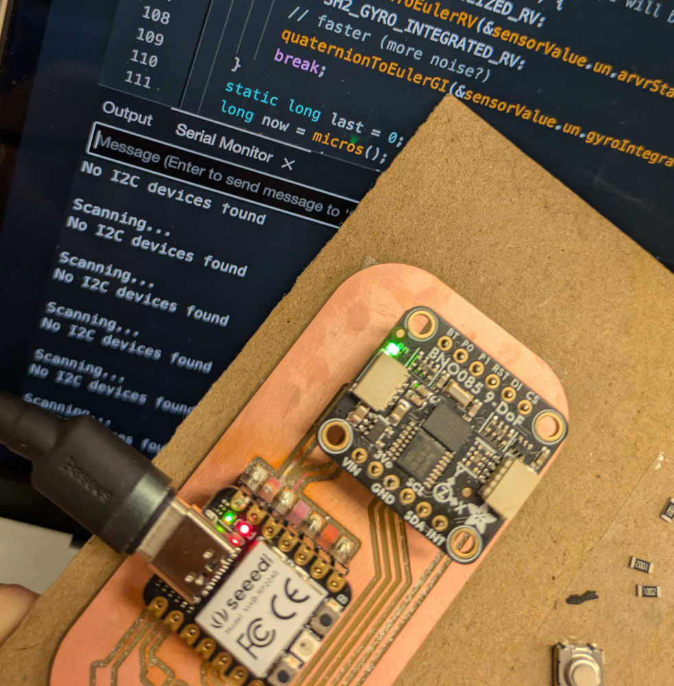
- Issue: Unable to read IMU; error message "I2C address not found"
- Solution: Download I2C scanner and run it in Arduino IDE.
- Also try pushing the connectors around at different angles; for components with loose fits (e.g. Adafruit BNO085 fits loosely into the connectors that come with it, while the SEEED XIAO RP2040 has a firm and secure fit) it can help to establish a better connection - it worked for my IMU.
- The Adafruit learn page for the BNO085 component has step-by-step instructions on downloading libraries to Arduino IDE, connecting the IMU to various microcontrollers, and example code you can upload to read the IMU (displayed via the Serial Monitor in Arduino IDE). Shown in the video below is the Quartenion example code showing pitch, row and yaw. The disruptions in the serial display are when the IMU connection was off a little, and I would press my fingers to the IMU to reinstate the connection.
- Be careful when using the heat gun for solder paste, and constantly move the gun away from the board to avoid melting plastic components and making the copper adhesive bubble.

Happy shiny solder and sad melted plastic connector. - Avoid soldering directly on expensive parts (like a 9DOF IMU) where possible, due to the risk of flux shorting your connections. Which was what I think happened to my poor IMU this week.

Looking at the problematic pins that appear shorted when testing it on the multimeter. 
No input despite IMU lighting up. Next up: to continue trying to scrub the flux away to repair the IMU, and to hopefully obtain another IMU but this time, no more soldering directly on the component!
Unfortunately our TA Diana was ill this week, so we did not have the opportunity to complete the group assignment as a section.
Addendum as of Nov 4: So the flux was not the issue and the IMU that I thought I had destroyed was actually functioning again (see video below)! TA Anthony explained that flux was not conductive anyway, so it would not have caused short circuits. After consulting 3 TAs across 2 classes (TAs Anthony and Quentin from HTMAA and TA Sean from another class on microgravity, Course 16.88), the unanimous consensus was that I should be soldering header pins directly onto the microcontroller and IMU breakout boards (SEEED XIAO RP2040 and Adafruit BNO085). See my documentation on Output Devices for further elaboration.
TA Diana also shared that we could use an oscilloscope to probe an input device's analog levels and digital signals, i.e. this week's group assignment.
