
Aijia Yao
Week 3 – Embedded Programming
September 2025
This week was mainly about building and programming an embedded system with microcontroller.
What I Did
- Follow this link to the group assignment.
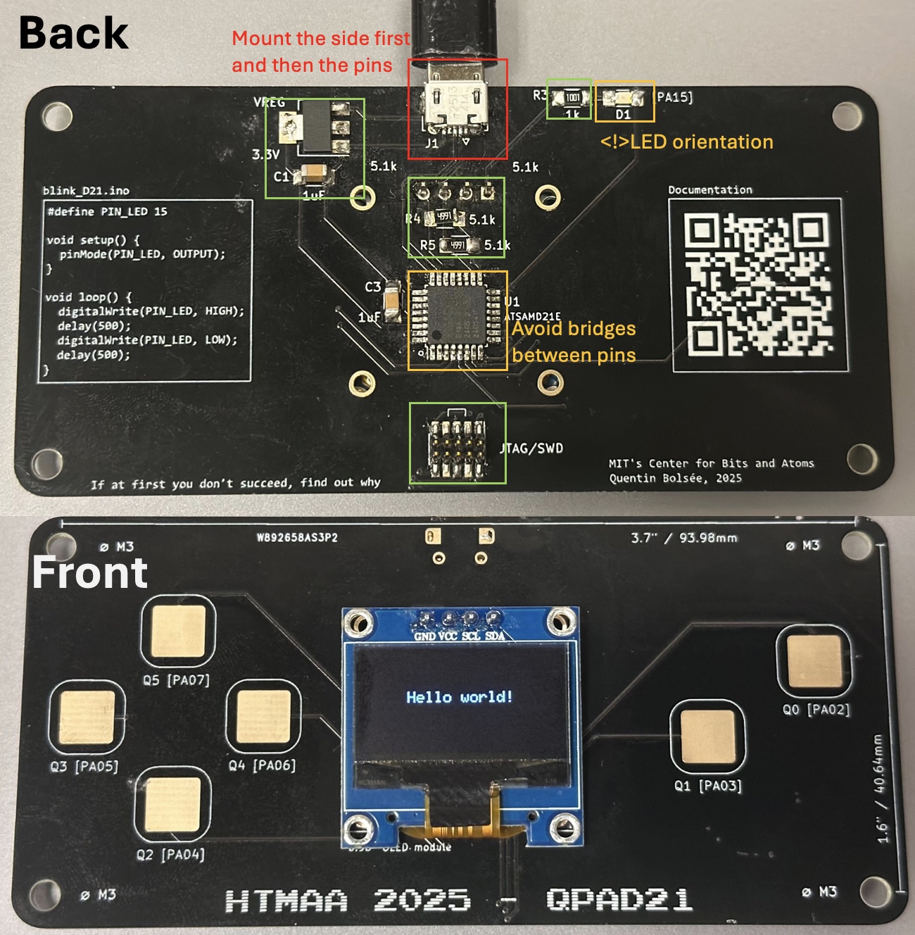
- Soldering all the components to the QPAD designed by Quentin Bolsee.
- Debugging the first soldering attempt, fixing connectivity issues.
- Testing basic functionalities of the QPAD, e.g. button, serial buffer and blinking LED.
- Designing a simple UI for the QPAD.
Assembling QPAD21
Notes for soldering
- Soldering paste is really useful for smaller pins.
- Burning hazard🔥, always put the iron back to the holder.
- I started with the microcontroller since I thought it was the hardest and it works well with the soldering paste:
- On the right I showed the final board after soldering.
- 🟩: easy and successfully soldered at first attempt.
- 🔸: succeeded in the first attempt but needs caution.
- ♦️: most challenging part, took more time to solder.
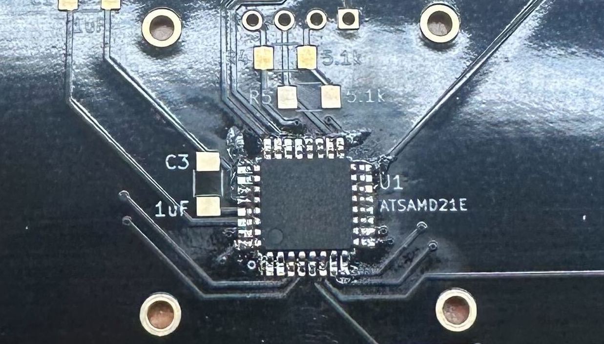
soldering result
For the microcontroller used here, it has an Arm Cortex-M0+ CPU running at up to 48MHz according to ATSAMD21E Datasheet.
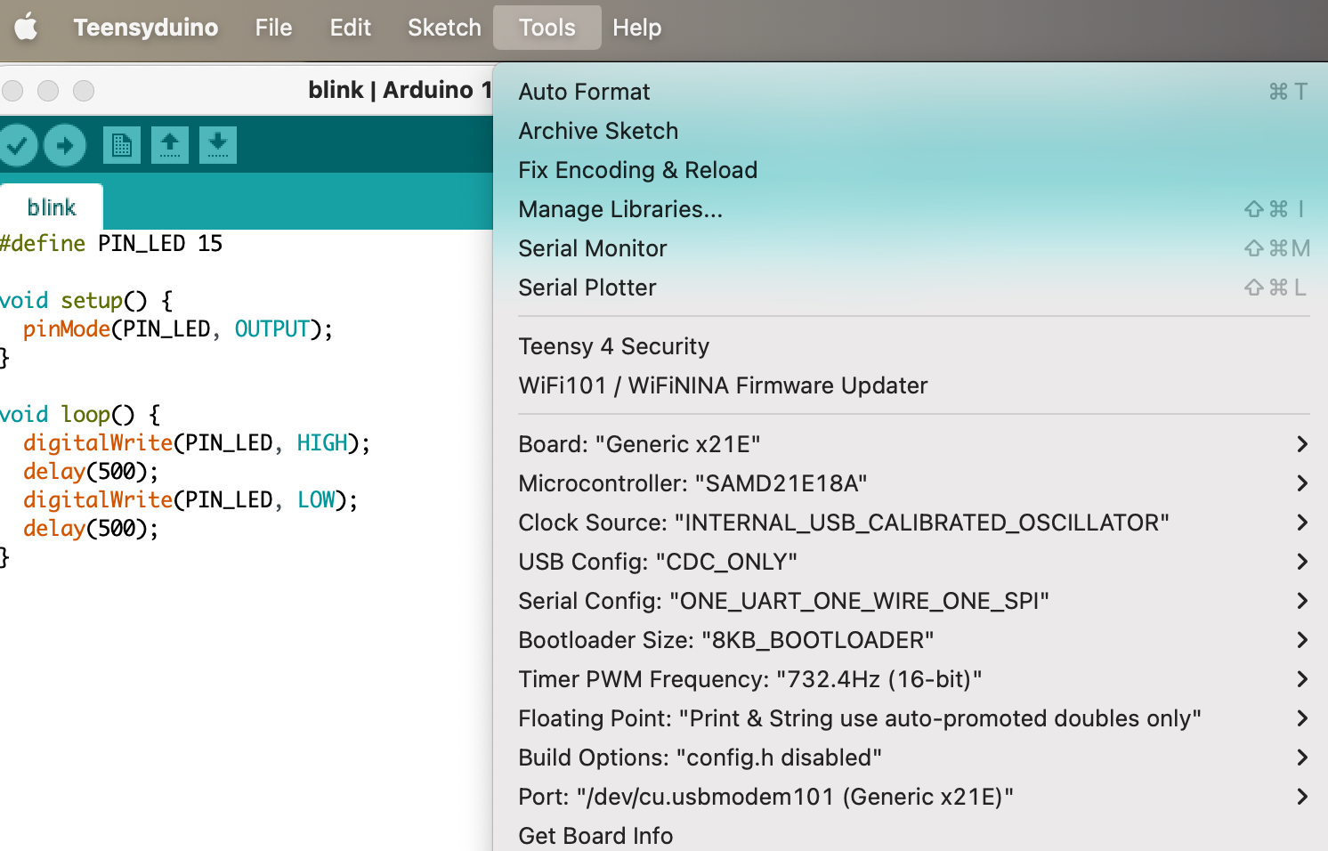
Before the initial testing and programming, TAs also helped us to burn bootloader onto the microcontroller, which is only needed for the first time of programming and it only requires connecting to XIAO-RP2040(See datasheet here) via SWD. Then the program sketch can be uploaded via Arduino IDE with 8KB_BOOTLOADER and setup accordingly:
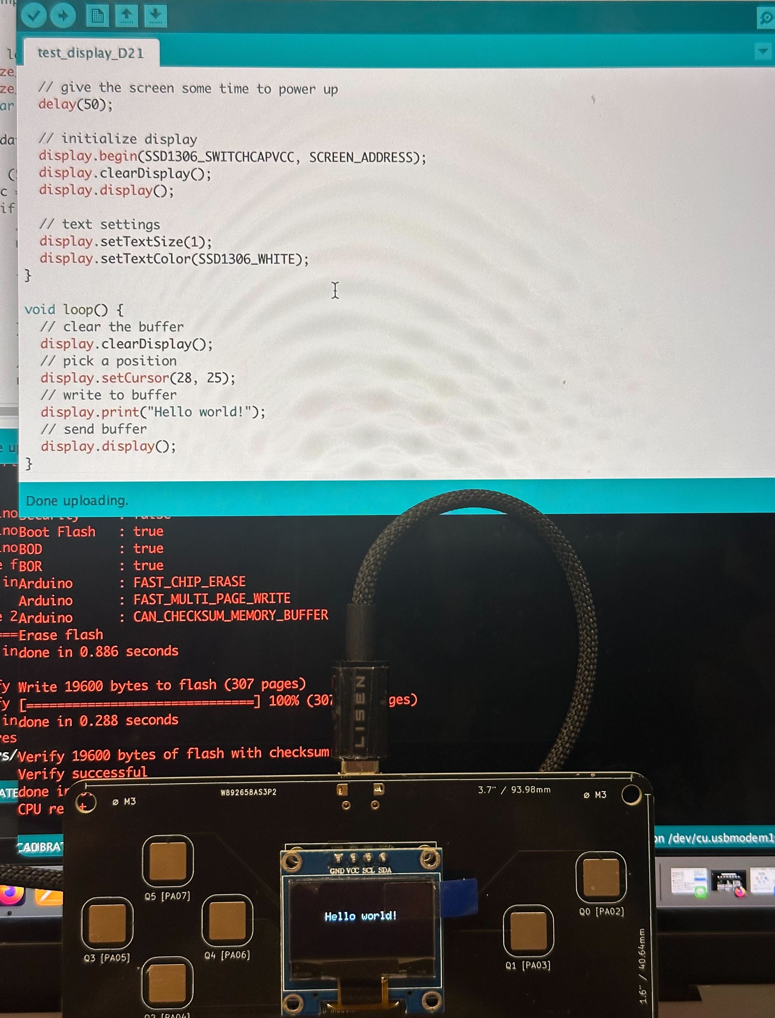
Basic Testing
"Hello World!
Serial Test
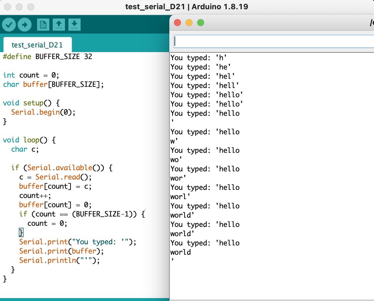
Sending text from the serial monitor to display on OLED screen:
Designing and Programming with Touch Pads
After testing the basic functionalities of the QPAD, I designed a simple UI with all six touch pads to control and draw on the OLED display. The UI is designed as following:
- Q0: Clear the canvas.
- Q1: Draw a stroke.
- Q3/4/5/2: Move left/right/up/down.
The touch pads are connected to capacitive sensing pins on the microcontroller, allowing for touch detection (though the caveat was at first i was testing the pads when my elbow is on my laptop, the capacitive sensor didnt really respond well because apparantly the laptop surface is conductive). The programming is done using Arduino IDE, utilizing libraries such as Adafruit_GFX and Adafruit_SSD1306 for OLED control, and CapacitiveSensor for touch input.
Other Notes
- The Arduino (cpp) code for the touch pad UI is available in the GitLab repository.
- It is not necessary that the component with the most pins are the hardest to solder, but the one that need to be robust and smaller/closer pins, in this case is the USB micro-B connector.
- Ackowledgements: many thanks to the course staff(shout out to Anthony for soldering intro&help and Quentin for debugging my connection problem in OH) and my peers for their support and feedback throughout this week. ChatGPT usage check here.