This week, before starting the group assignment and device assembly, I wanted to spend some time familiarizing myself with the
with the "QPAD-xiao" device that we would be using. For my assignment I chose the QPAD-Xiao version which uses an RP2040 chip because this chip allows WiFi access which I may need to use later in the semester, for my final project. I have never experimented with embedded programming or any electrical components before, so I took the following notes for my own understanding:
The QPAD-xiao is a circuit board. At its center is the
RP2040
microcontroller by Raspberry Pi.
A microcontroller is a complete processor, like a tiny computer. It is the part of the circuit board that executes code to control everything else. It is a type of chip.
As a tiny computer, a microcontroller has both processor cores and memory.
Microcontrollers can be programmed in various languages other than assembly language, but they can have memory issues or run slowly when reading high-level programs.
The QPAD-Xiao can be programmed from the Arduino IDE, using Arduino libraries.
The QPAD-Xiao requires a bootloader, which is a small program that starts the computer.
In order to use Python with the QPAD-Xiao, a special CircuitPyhton firmware is necessary. This can be compiled witht he UF2 bootloader according to Quentin.
Since I am already fluent in Python I wanted to try the Arduino libraries this week; it has been a long time since I used any C based language.
I wanted to use the Cloud IDE but it seems to require a device that connects to the internet which the QPAD does not (even though the RP2040 can?), so I downloaded it.
I then followed Quentin's instructions to set up the Raspberry Pi Pico Arduino core for the RP2040 board. Without the board in hand, installing the board configuration was as far as I could get in the IDE.
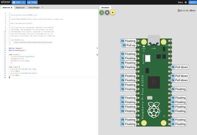
In order to keep exploring, I went to the WOKWI Raspberry Pi Pico simulator and tried some code. I started from Neil's example but noticed the board in the simulator didn't have any buttons, so I removed the button input components and simplified it to just blink the LED every 200ms:
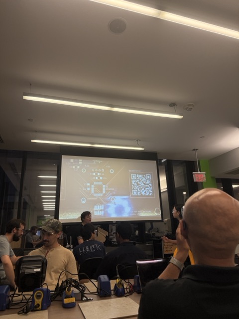
Embedded Architecture Toolchains
We reviewed the specifications and processes for different embedded architectures offered in the class. I made this page to hold notes from everyone in this section. Further detail is also available here, as we are still consolidating how to represent these assignments.
Data Sheet
Because the QPAD-Xiao uses the RP2040, I read through the RP2040 data sheet.
While this document of 636 pages initially seemed verbose and more granular than I would understand, I actually found the introductory section very useful. The following passage was good context for this assignment:
Microcontrollers connect the world of software to the world of hardware. They allow developers to write software which interacts with the physical world in the same deterministic, cycle-accurate manner as digital logic. They occupy the bottom left corner of the price/performance space, outselling their more powerful brethren by a factor of ten to one. They are the workhorses that power the digital transformation of our world.
I also learned that this microcontroller is the first one produced by Raspberry Pi.
Most of the datasheet was filled with lists and tables about ports, registers, pins, states, and other settings. Based on this structure I think this document is primarily useful as a lookup index for specific aspects of the device, rather than as a primer for how to use it.
Device Assembly
In Recitation this week we assembled the circuit boards for the QPAD. Anthony gave a very helpful training for how to solder using both traditional solder and solder paste:
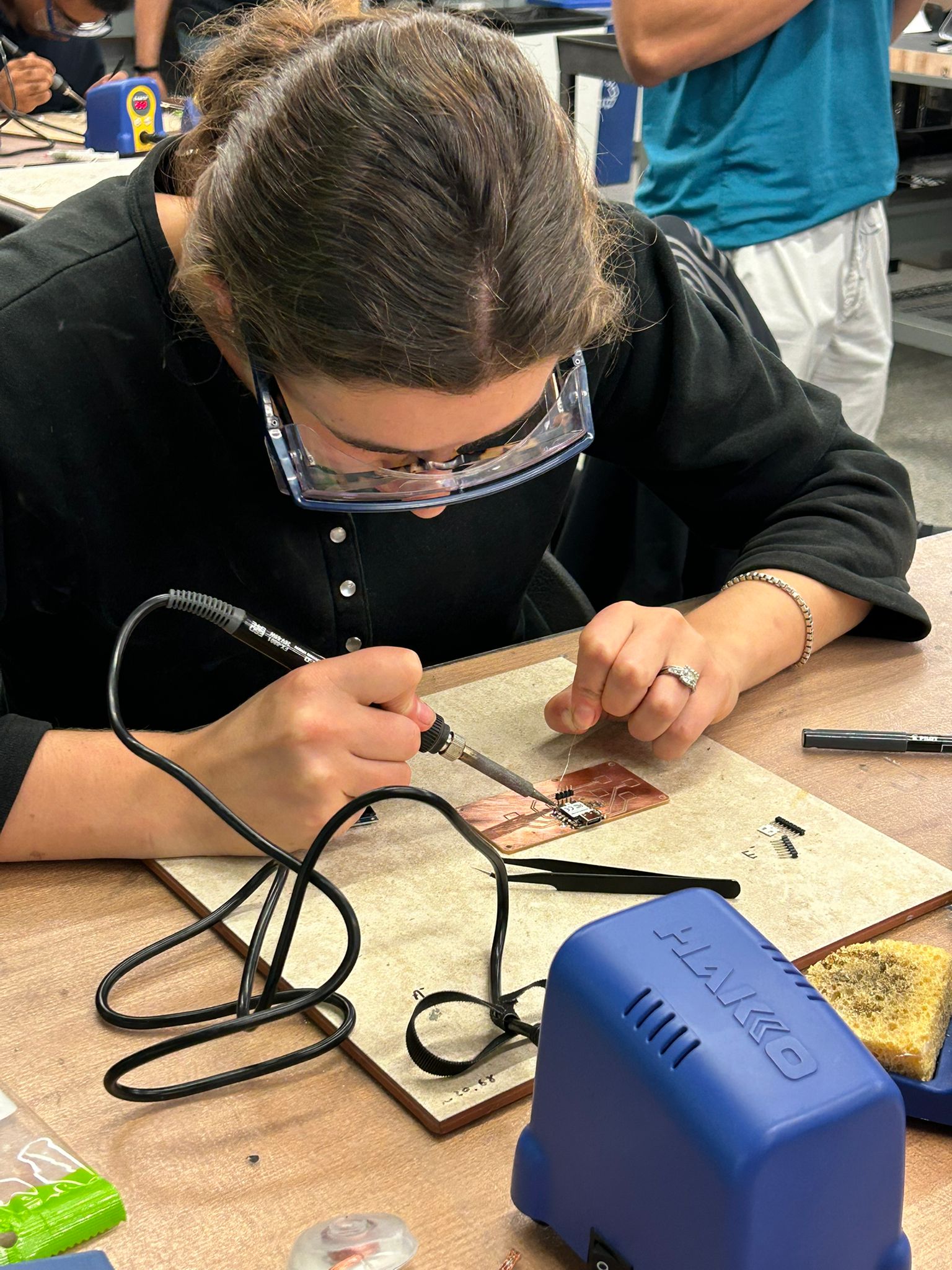
I chose to assemble the Xiao RP2040 version of the QPAD, choosing the RP2040 for the WiFi programmability reasons described above and the Xiao for its friendliness to a beginner-solderer. Avi Gilad took this photo of me soldering it together:
There were not many points in the board that needed ot be soldered beyond the pins of the Xiao. I found that controlling the solder was a challenge, but by the time I had finished the pins and moved on to the two resistors, I was getting the hang of it. I added the display and took my QPAD home.
Display Communication
In order to experiment with the display, I started with Quentin's test_display.ino code. At first I just ran it with the device plugged in but was missing dependencies; this required installing the Adafruit GFX library and the Adafruit SSD1306 library, which I did in the Arduino IDE.
My next hiccup was an error in whcih the IDE found "no drive to deploy;" this seemed to be an issue with my cable whcih was power-only (I had to use my own because my Mac did not have a port for the provided ones).
I switched my cable to a data cable. Then, I held down the bootloader button to load the right disc and used the Arduino IDE to upload the sketch. While everything wrote properly, I was stuck on the display: my Serial Monitor showed that the sketch was running, but nothing would show up on the screen. Since the code was downloading and running I knew the microcontroller and laptop were communicating properly, but my screen was causing an issue.
I brought the board in to Anthony who observed two issues:
1. my microcontroller was not soldered to ground.
2. the pins of my screen had pulled away from the board, dragging some of the copper plating with them.
The first problem was easy to solve, so I added the missing solder. The second was harder to solve since the printed copper of the board had ripped of, disrupting connections between the display and the microcontroller. We decided to fix this using wires, which could be soldered directly to the pins necessary for connection, passing from the back to the front of the board.
Attaching these was another chance to practice my soldering skills, and I learned some new tricks like holding components in place with tape until they are soldered, testing connections with a multi-meter, and hot-gluing wires in place once they are proven functional.
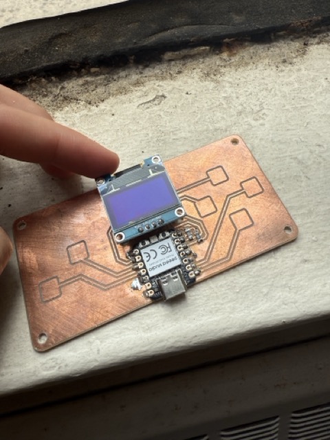
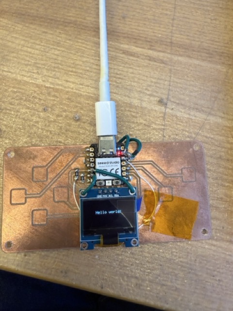
Once the screen pins were re-wired we downloaded code again and still saw no response from the display, so we concluded that the screen element must have been disconnected from ground-- a problem that we couldn't see because it was a scratched area of copper underneath the component. With one more wire fixing that connection, the screen finally turned on!
Embedded Communication
I started playing with the display by adapting Quentin's test_display_RP2040 program. I wanted to be able to show text and graphics, and to respond to input from the Serial Monitor.
In order to demonstrate these skills, I decided to build a very simple implememntation of the I-Ching divination machine. I was already familiar with this amusing online version of the book of changes, and found by searching the class site that Lingdong Huang did a final project on this device in 2021.
My version is highly simplified relative to Lingdong's and it follows the digital-native version of the casting system from the online I-Ching rather than the more complex original version he implements in a physical box. Each hexagram of the I-Ching consists (naturally) of six linear elements. These can be either
yin
(broken) or
yang
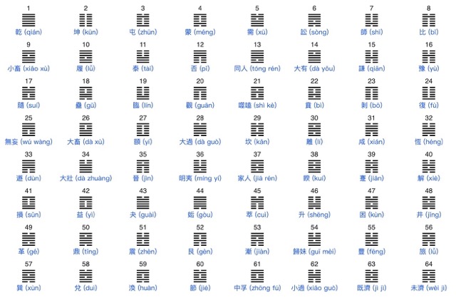
(unbroken). This set of 6 independently-cast broken or unbroken lines results in one of 64 possible hexagrams, each of which has a name and a meaning:
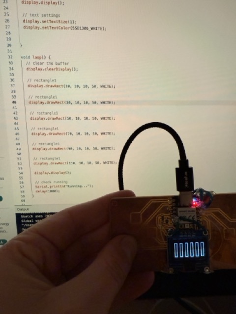
I wanted my display to generate a hexagram in response to a question. I started by using the Adafruit GFX Graphics Primitives to draw rectangles:
Next, to simulate casting and "generation" of rectangles, I added a question prompt and started generating the lines of the hexagram by randomly choosing between a solid or broken line at each location. This used the functions
random()
and
display.fillRect()
.
I added some drama by displaying the "..." and the rectangles one by one. This just meant putting a
display.display()
after each new component:
Then, in order to facilitate user interaction, I programmed it to handle a string from the Serial Monitor as a question. It took some maneuvering to make sure that the string split lines on natural breaks, only printed new questions from the Serial input, and appeared at the right spacing, but the following is the result:
The hexagram we received about tomorrow's weather is Hexagram 22, called "bi," and signifying "adorning," "bright," "grace," "lush," and "luxuriance." My weather app says about 90% chance of rain, and in Lincoln where rain means beautiful drops on the green forest and pleasant sounds on my roof, this prediction seems about right.
Trials and Tribulations
Following are some observations of the process this week, and some challenges or disappointments to record:
I found soldering challenging and due to misunderstanding the way the board worked not only incompletely / improperly soldered some components but also entirely didn't solder a crucial pin.
Because I mounted the screen too high the first time I soldered it, my board was very fragile. This caused the cracking that took a long time and numerous wires to fix.
Learnings and Progress
Below is the delta between where I started on the skills for this week and where I arrived:
I had never read a circuit diagram before, didn't know what a microcontroller was, and had no idea what it meant to connect to ground; I learned the basics of how circuits and their components work.
I soldered electrical components together for the first time.
I hadn't used C++ in a long time but revisited it in the Arduino IDE, and it came naturally except that my Python reliance has me missing semicolons left and right!
Resources and Acknowledgments
Shoutout to Anthony for spending an hour with me fixing the broken board and showing me how to wire everythign properly; patience of a saint, truly.
Of course thank you also to Quentin for inventing the QPAD and offering the beginnings of code for it.
For the rest of my coding questions, the Arduino IDE Docs were by far the most useful resource.