6.9020 HTMAA Week 07
[group work looks like this!]
Computer-Controlled Machining
This week I was out of town during class and recitation, so my learning process for the content this week was slightly different from usual. I perused the course page from lecture and found the Fusion 360 Cam Introduction and Toolpaths tutorial particularly useful. The most specific and helpful content for my learning this week was Anthony's CAM in Fusion video, which I followed closely.
My objective this week was to continue (redeem?) my project from Week 2 in which I laser-cut a prototype of a customized shelf for my desk area at home. There were several aspirations I had in the course of modifying this project:
Designing in 3D
: Since I was learning Rhino (and parametric design) for the first time in Week 2, I chose to design my components as a flat-lay and cut them directly out of that file. While this was initially simpler to look at, it created vulnerability to problems down the line as components didn't fit exactly right together. This week I'll use Fusion to design in 3D and cut from there.Stabilizing Joints
: My cardboard implementation had some stability issues due to its (crucial) slant. These were caused by the weight of the slanting side pushing forward against the straight side, so that the straight side angled forward slightly. I believe this issue was due to a lack of rigidity in the joints and will make these stronger this time. Making OSB look good
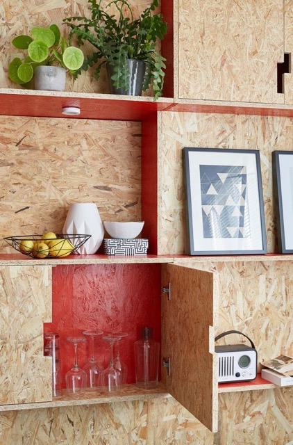
: I am hoping that the project this week will result in a useful item for my home, so I spent some time on Pinterest looking at inspiration. My observation was that OSB seems to look best (and be most stable?) when it has at least some closed volumes, rather than treating it as thin boards. This is reinforced by the recitation notes, which recommend avoiding long, skinny elements.
This means that I will be designing something that brings a sensibility like this:
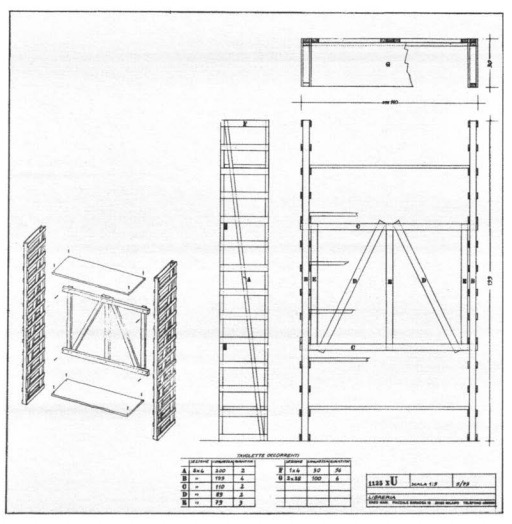
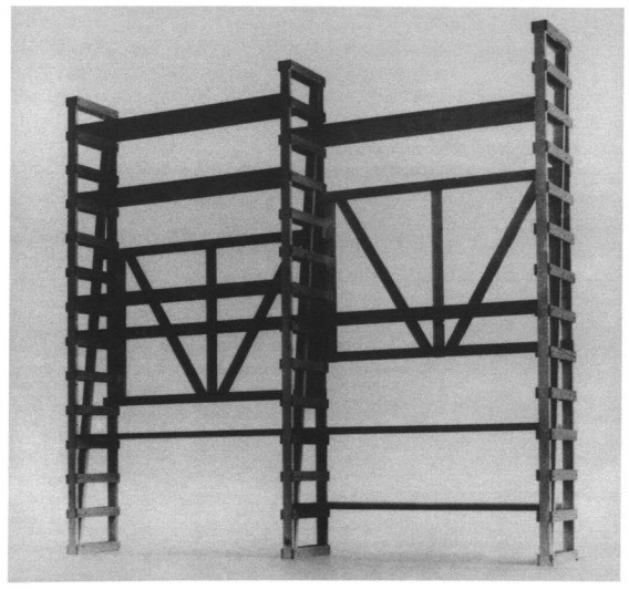
 To the original Enzo Mari inspiration here:
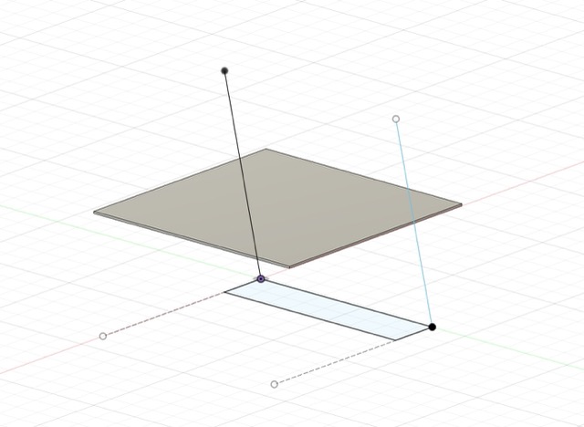
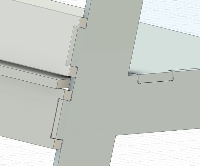
 A final adaptation, which I think will be helpful in my efforts to accommodate my assembly skills in CAD (rather than accommodating my CAD skills in assembly), will be that I'd like to prefer 90-degree (XY) press fit joints rather than those that go through an entire board or attach two boards at a 90-degree (Z) angle:
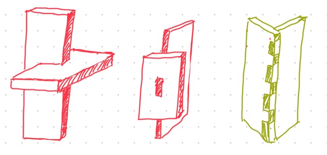 This preserves more degrees of freedom in the dimensions of the peg, which leaves me more room for error.
CAM Design
I started by downloading the Nifty Dogbones plugin, and by watching the video on the page which was informative. I then read the Recitation Notes online to get a full picture of this process, which has the following components:
Designing
the full assembly in 3D, in CAD.Path Planning
using the machining software in Fusion to create a "setup" and simulate the toolpath of the machine.Milling
with the big router.Refining and Assembly
, involving polishing edges and removing tabs so that the finished item fits together neatly.
I began updating my design by sketching in Fusion; it is clear that the way to make parts fit like this is to sketch on the appropriate plane, and then extrude. I started by making a simple sketch of the area where this shelf will go, as well as the size of OSB piece available:
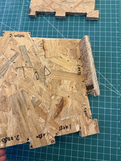
I learned from our group test that for a
2 in
peg, the corresponding slot should be
1.997 in
to ensure a tight fit. There is no kerf for this form of machining, so those will be the dimensions of my joints. More on group work for this week is available here.
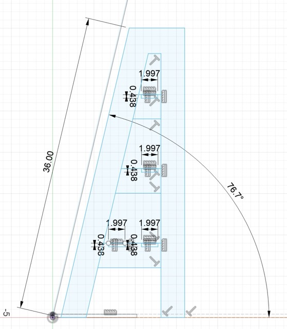
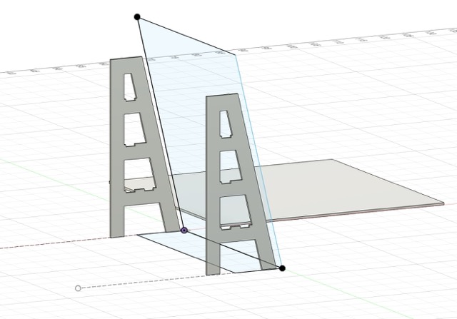
 To put in place the main structure of the shelf, I sketched one of the vertical legs on a vertical plane:
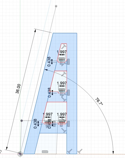
 Then I selected only the areas that would be cut into the wood, so that they could be extruded:
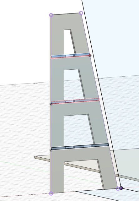
 Once this was extruded to the 7/16" depth of the OSB, I duplicated it to create the other leg:
 In order to create the shelves, I drew a 7/16" profile across one vertical leg, intersecting with the joint slot at each level:
 Then, I extruded these to create the horizontal shelves.
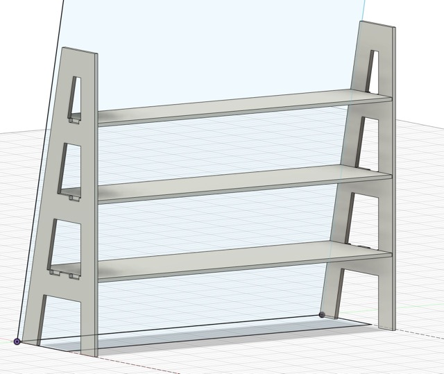 I repeated the same process, sketching on the slanted plane of the shelf backing, to create horizontal support elements across the back. There are two of these for each shelf; the lower one is designed to help support the shelves, and the upper one is inteded to offer a backstop since the angle makes it hard to see where the shelf ends on the slanted side. For each of the horizontal elements, I finished by sketching a joint peg in the window of the joint slot, 2" wide, and using the "push/pull" function to extrude it through:
 The finished product!
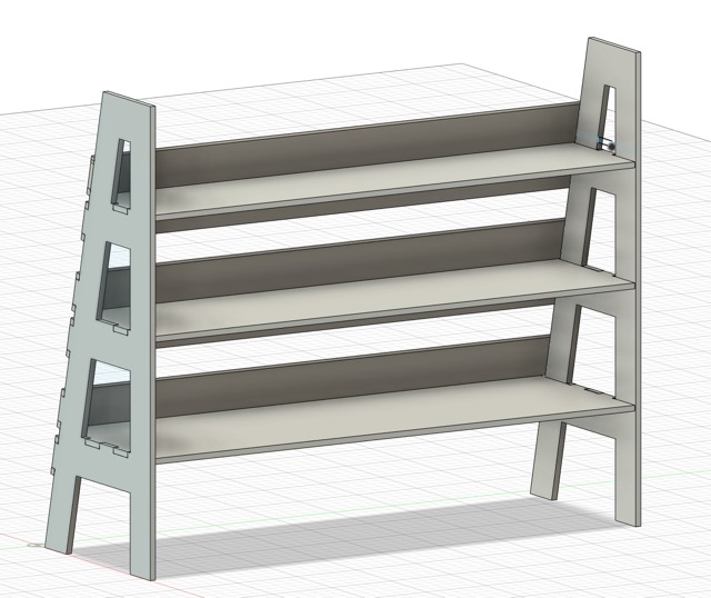 With the completed model, I could move to prep for machining.
Path Planning
In Fusion, there is an interface for preparing to machine things with various kinds of machines. For 2D machining (our case), the workflow is to create a "setup" by adding components of a 3D model to a 2D plane, and defining settings that control the toolpath on that plane. For this part of the assignment I followed Anthony's video VERY CLOSELY and I recommend that anyone else attempting this for the first time (hello, future years?) does the same.
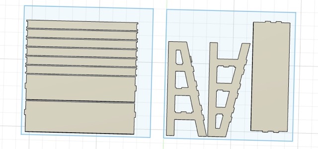
Per the video, I created a 48x48" stock to contain my components and selected faces from my 3D model to place in the cutting area. I needed two of these, since my components could not all fit within a single sheet of OSB. Each zone corresponds to a separate "Setup," which refers to a milling job with the required settings.
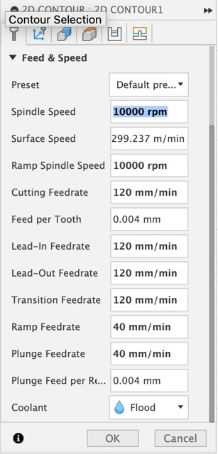
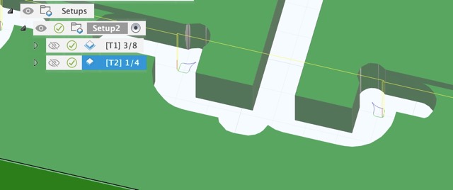
 For each setup, it was necessary to creat two 2D Contour jobs, corresponding to the 3/8" Flat Endmill and the 1/4" Flat Endmill tools respectively. For each one, we defined settings relative to the operation of the mill:
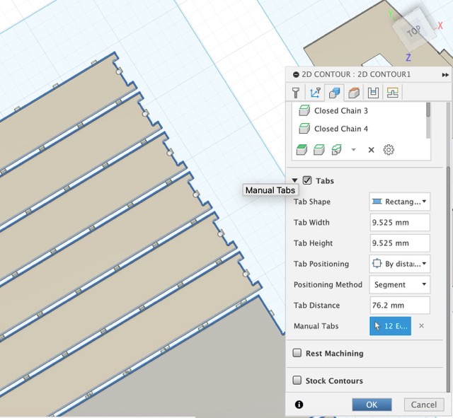
 As well as automatically and manually adding "tabs," which are half-depth connections between free parts and the stock, so that the parts don't fly away while we're cutting.
 At the end of this process, we are able to simulate the toolpath. This is visualized in Fusion as material removed from a green slab of stock. Upon zooming in closely it is also possible to see different paths with the different tools:
 Finally, we can simulate the toolpath to visualize how the parts are separated from each other and from the stock. After checking this, we can export gcode that is ready for the mill to read.
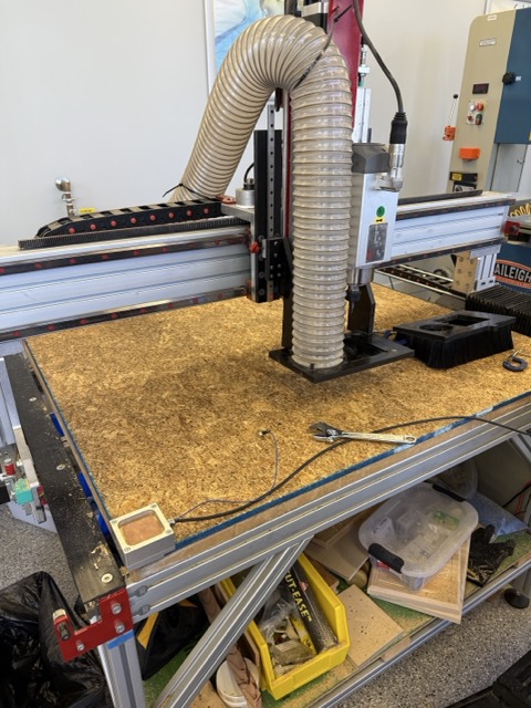
CAM Safety and Setup
Before cutting, we reviewed the safety aspects of the mill and the process of setting it up. This involved attaching the stock to the base board using plastic nails that would break off later, and after the stock was attached, using an electromagnetic block to set the X-Y-Z axes of the machine:
 This is necessary to do, at least for the Z direction, each time the tool is changed (between the 3/8" and 1/4" endmills). It is crucial to wear safety glasses, check the feedrate settings, and watch closely when milling.
Machining
To cut the components, we loaded my gcode into the machine and then cut with the 3/8" (big first) followed by the 1/4" (small second) tools. Below is an image of the machine cutting my parts, with the settings visible:
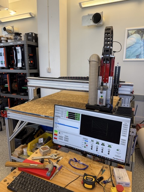 Each job took about 10 minutes. After cutting, I vacuumed the stock, used a crowbar to crack off the stock and parts from the base board, and then vacuumed again.
Assembly
In order to assemble the shelf, I used the below tools to refine my pieces and make them fit together. These include an electric file for shaving off the tabs that connected the parts from the stock, and then a rasp to make the edges smooth.
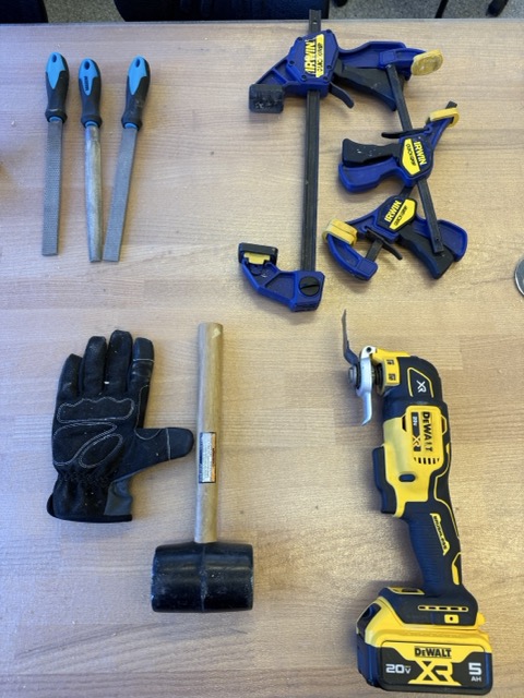 After finishing the parts, I pressed them into place at the joints, and whacked them down with the mallet to make sure they fit in place.
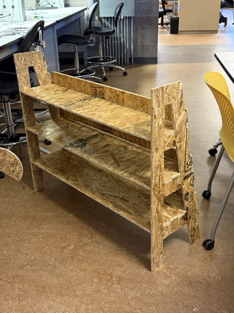 This was sweatier and sawdust-ier work than I was expecting, but the shelf came together! In the end, I think the horizontal support elements are actually not very necessary or useful, since the OSB is barely strong enough to hold up in that long-thin aspect ratio and since attaching slanting joints to one another was more trouble than it was worth. Nonetheless, this is a piece of furniture that fits in my house, which is more than can be said for most pieces of furniture!
Trials and Tribulations
Following are some observations of the process this week, and some challenges or disappointments to record:
- At first some of my settings in the CAM simulation were off; Anthony helped me adjust my feedrate to bring the cutting time down, and I had one piece whose sketch was not connected properly and had to be re-extruded. Overall 3D sketching in Fusion did go well though.
- OSB is really a quite nasty material though I do understand it's cheap and big, and these are the reasons we use it for this assignment. I found it piecy and unpleasant to handle or file down, and I accidentally whacked off part of one of my joints with a mallet during assembly because it was prone to cracking.
- When making something big, it is hard to get it out the door! For future generations: do be careful of the fire alarms that have been mounted on either side of the doors leaving Building 38, right at project height :)
Learnings and Progress
Below is the delta between where I started on the skills for this week and where I arrived:
- In comparison with Week 2 especially, I think I've learned much about how to design and fabricate something in 3D-- primarily that weaknesses in CAD cannot be fixed later so it's crucial that the CAD actually reflects the design (in 3D).
- I am especially proud of having made Fusion do all the trigonometric calculations I did for the first version of this shelf, which made things much faster and easer.
Resources and Acknowledgments
Thank you to Anthony and Jesse for the help in the shop, it's always a pleaure. Special shoutout to Anthony for helping me troubleshoot issues in my files via email late at night.
Design Files
My Fusion project is in the course cloud online.