Group Assignment
- characterize the design rules for your in-house PCB production process
- submit a PCB design to a board house
Individual Assignment
- make and test an embedded microcontroller system that you designed
My goal for this week was to get started on my final pcb production. See Week 5 for design overview
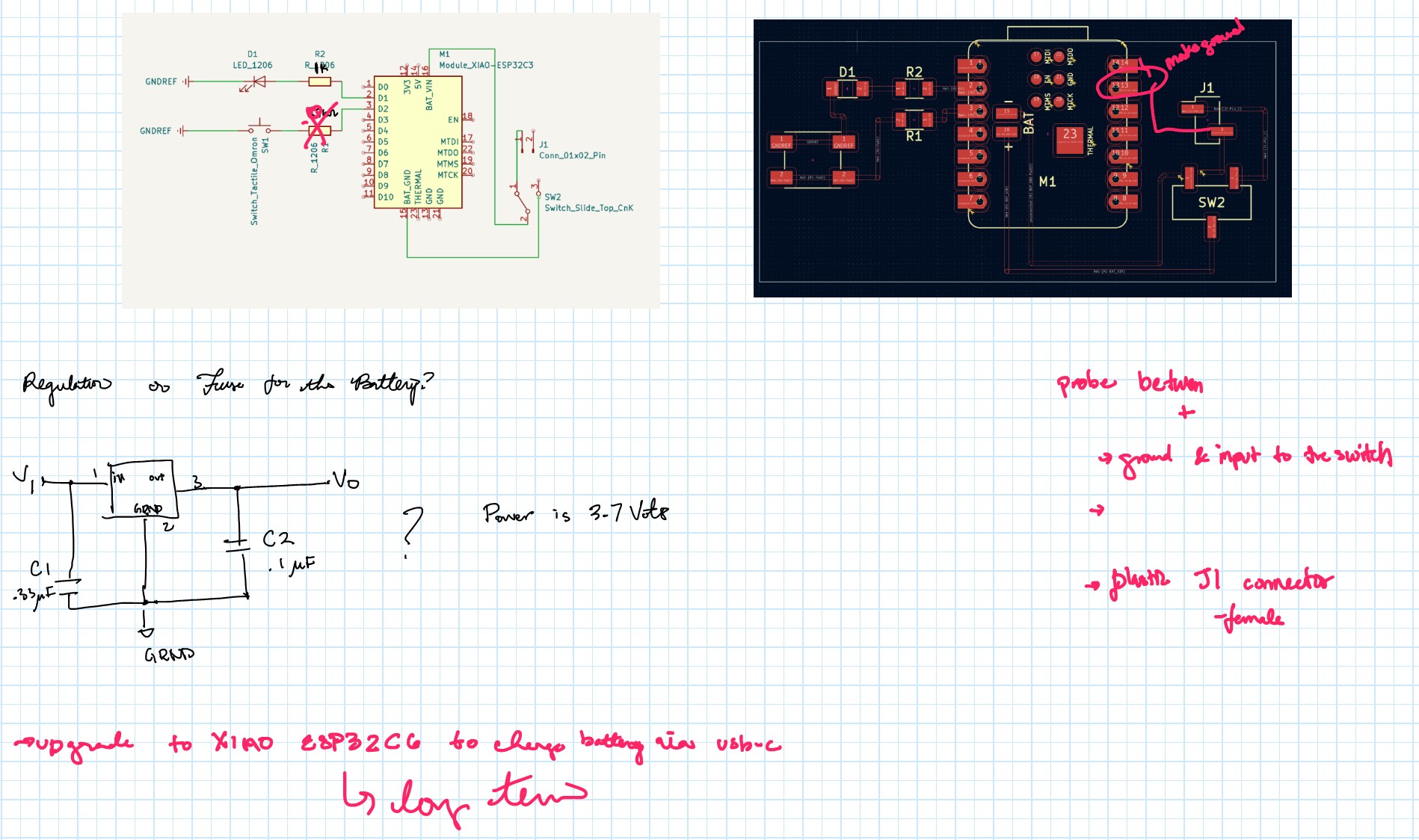
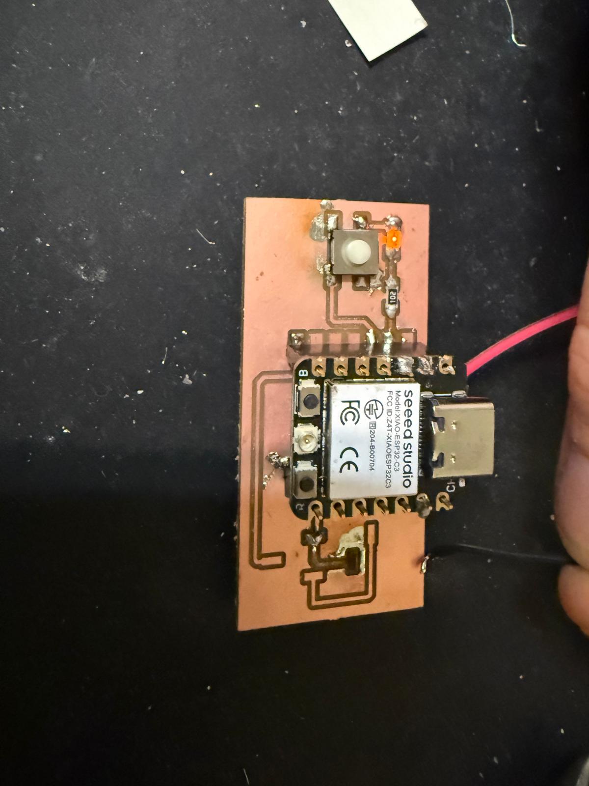
This week was mainly a learning experience, filled with several setbacks but also valuable lessons. On Thursday evening, Quentin led a training session for CBA on how to operate the Carvera Milling machine. It seemed straightforward, and I thought I would finish the production component quickly and have plenty of time to explore other ESP32 features I want to use for my final project this week. I was wrong. On Friday, during office hours, I asked Anthony a few questions about my board and the process of adding a battery. He pointed out a design mistake: I had included a resistor for the Switch Tactile Omron, which was unnecessary.
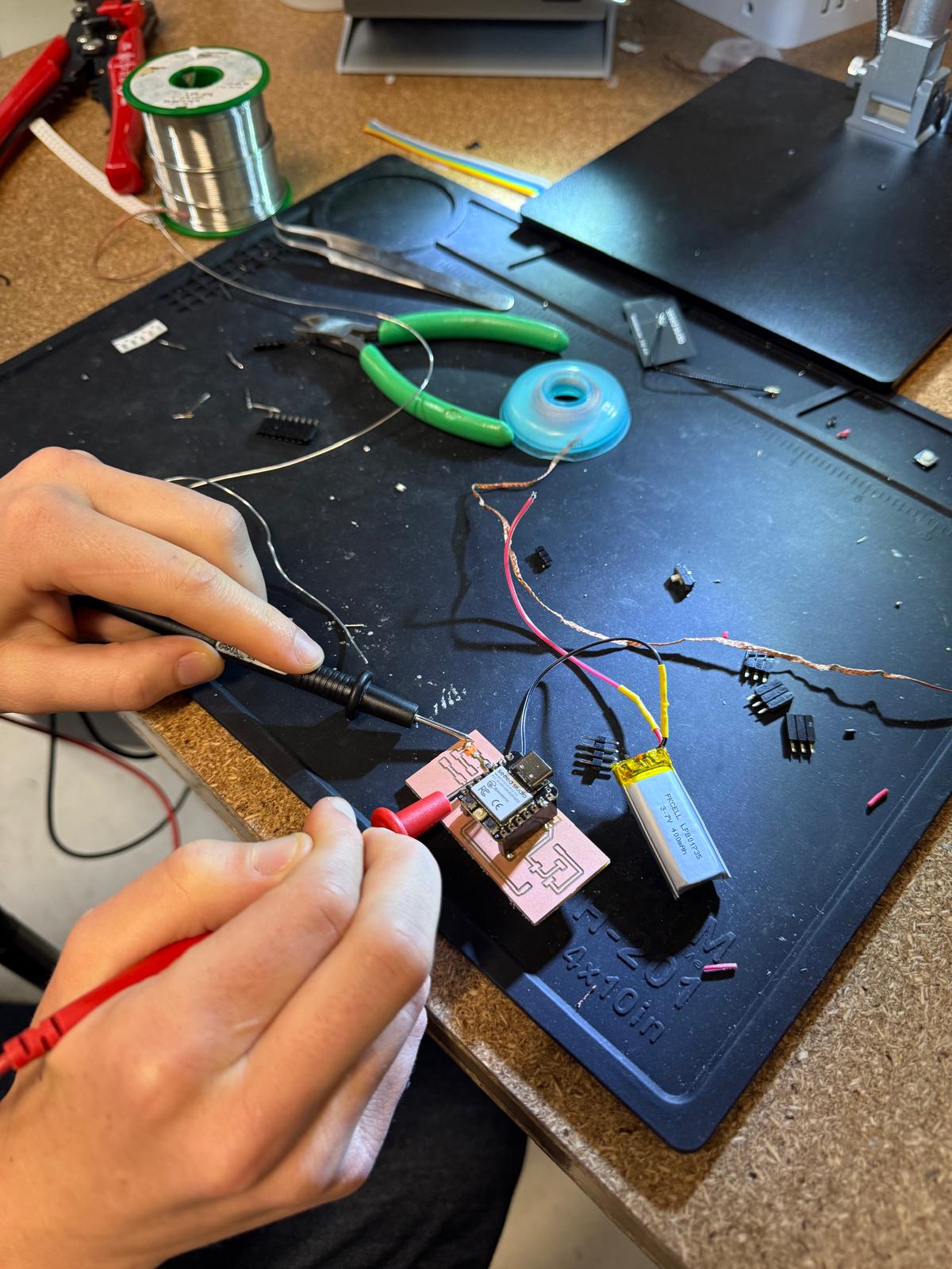
Quentin helped me locate a battery and a XIAO ESP32C3 on Friday. This leads us to attempt 1.
I used quentinbolsee.pages.cba.mit.edu/gerber2img/ and mods to generate the g-code for Carvera. However, the through holes for the XIAO ESP32C3 did not show-up when I looked at the Tool path on mods. I was confused, but decided to print anyway and see if they magically showed up.
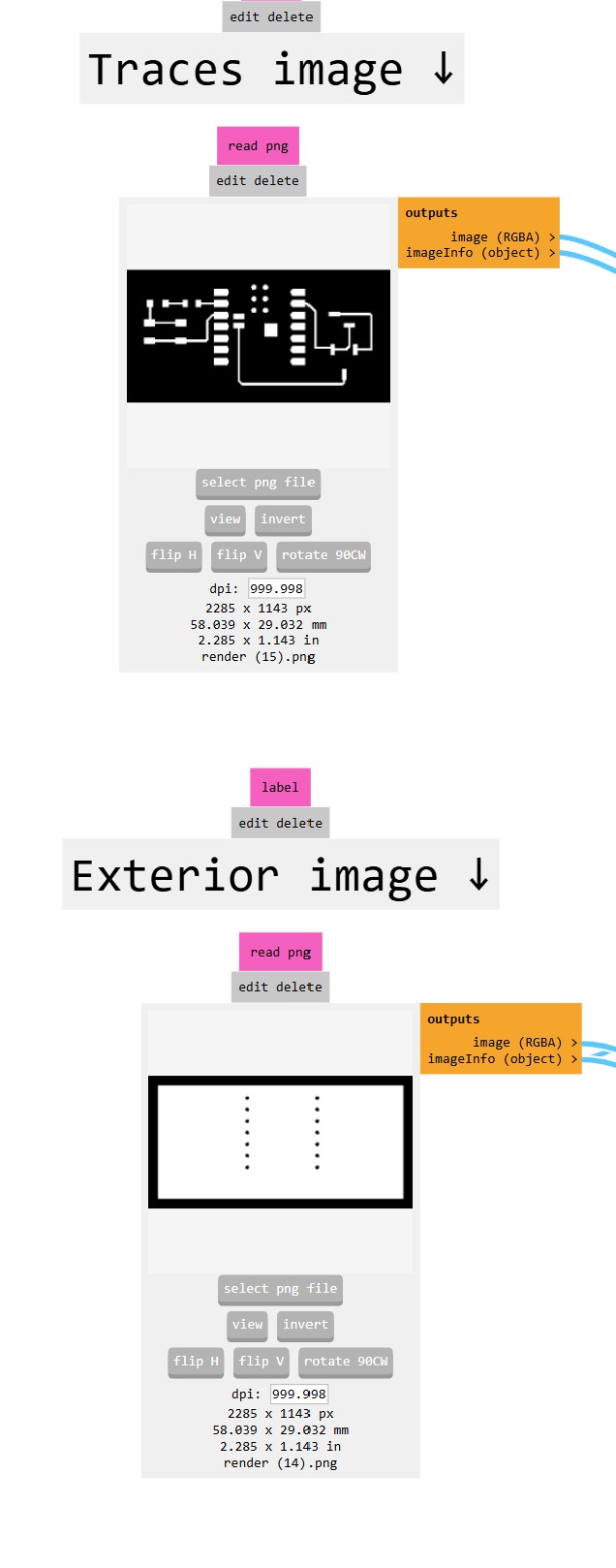
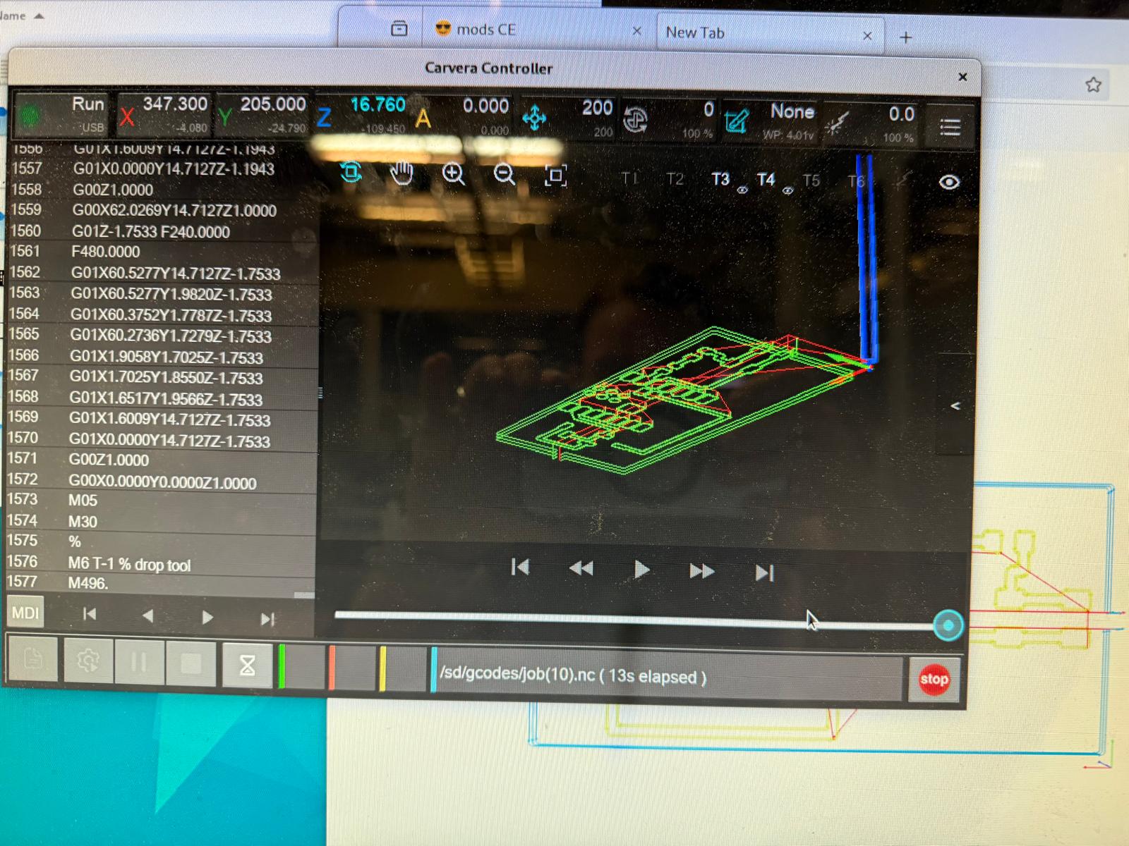
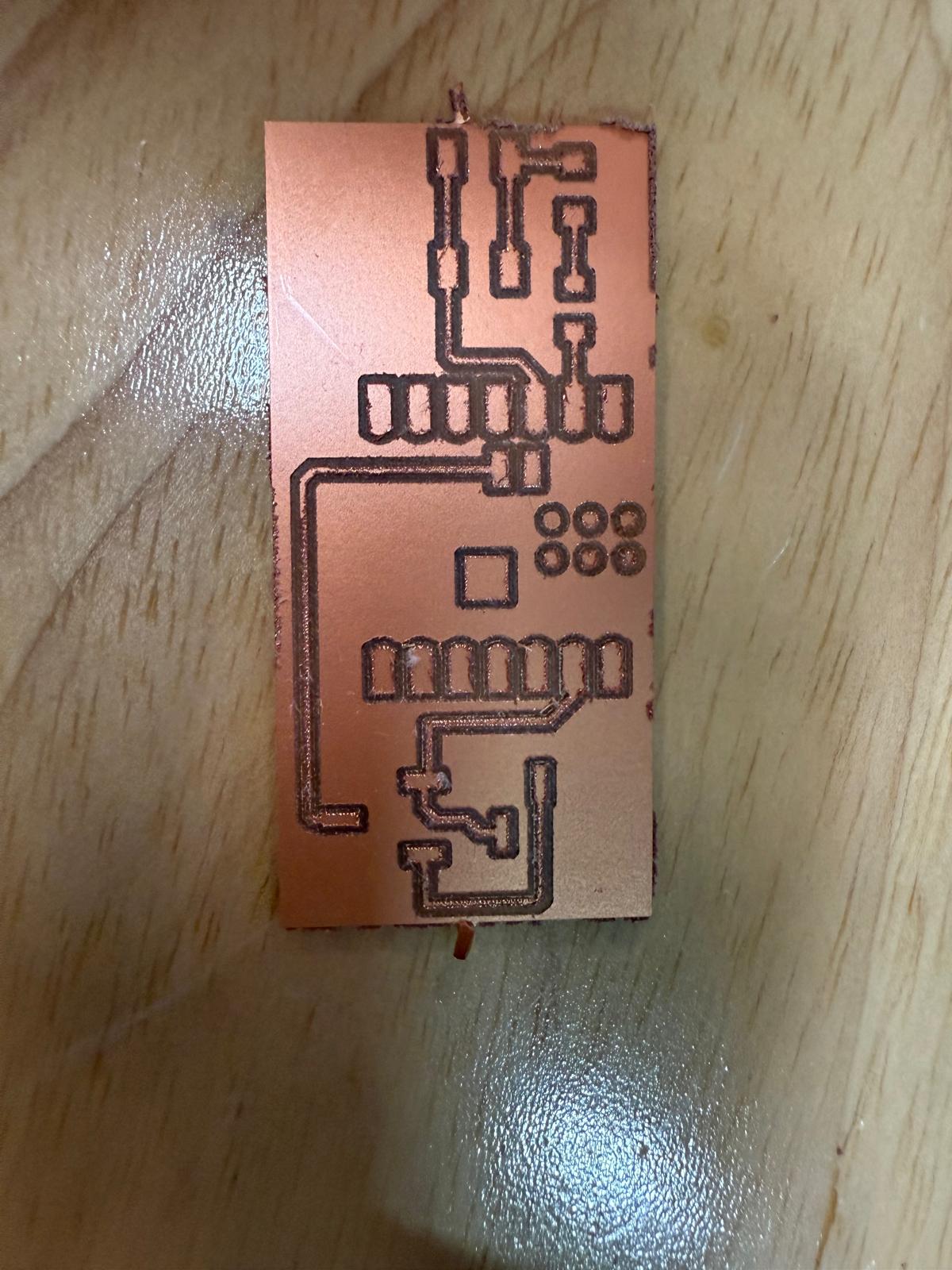
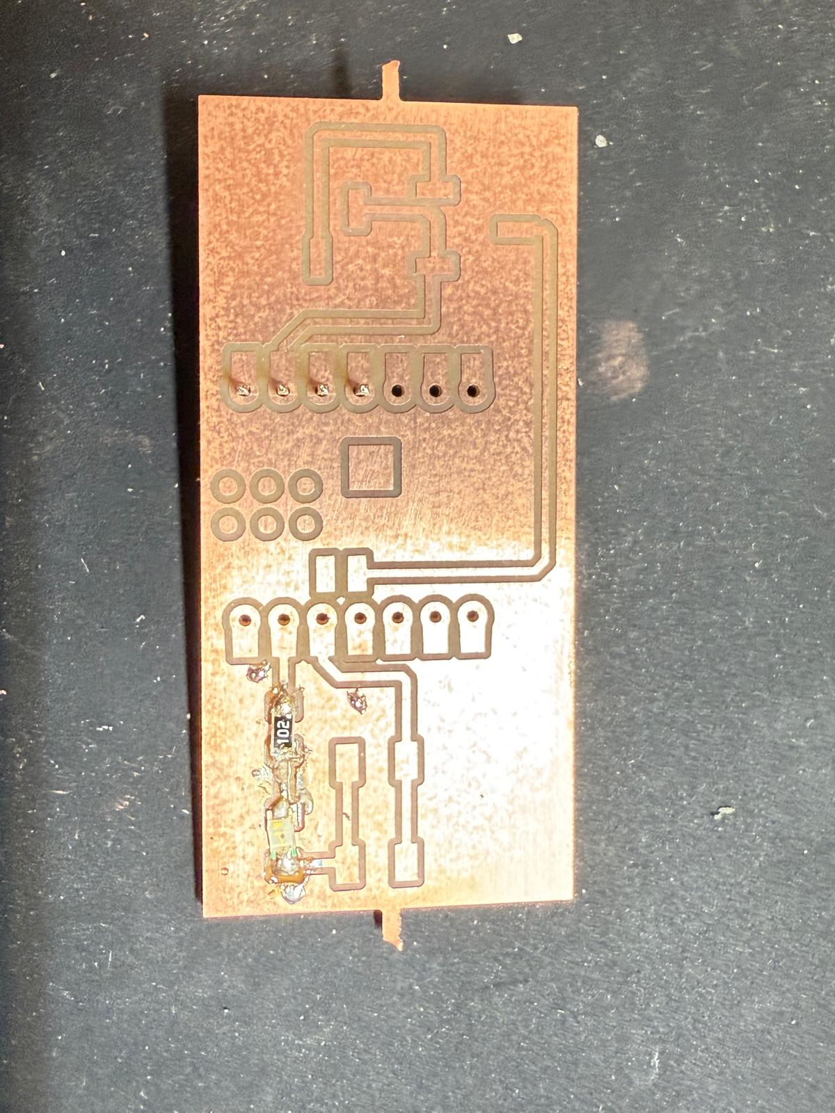
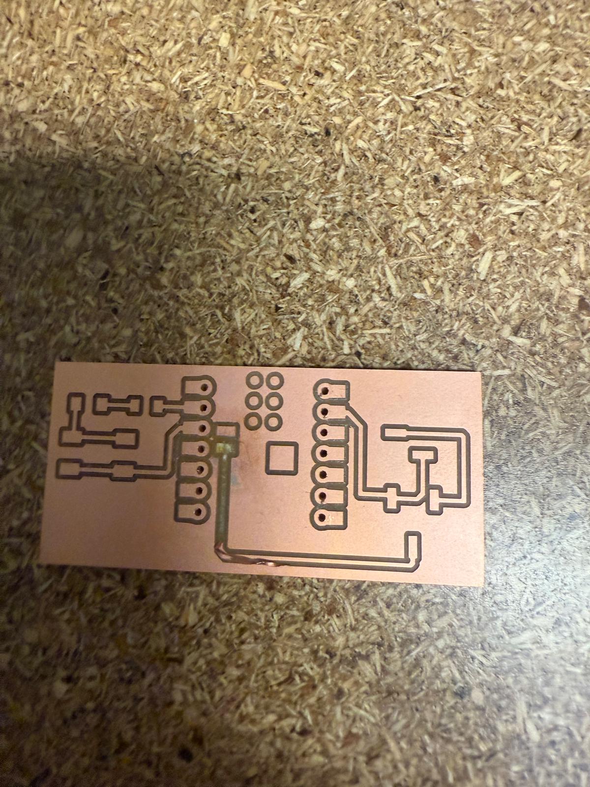
There are many things wrong with how this board turned out. Luckily Kristof stopped by Sunday afternoon to see if anyone needed help. He told Miranda and I that it was likely due to the tool being broken (Quentin had changed it on Thursday, so we thought it should be fine). He helped us change it. I also asked Kristof about the through holes not showing up and he mentioned that it was likely due to the diameter of the holes being too small. So, I modified the footprint in KiCad and changed the diameter of the hole from .8mm to .9mm.
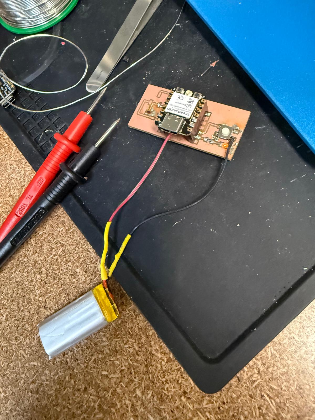
The board turned out very well; it was quite difficult to push the pins through. The purpose of the pin hole was to make my controller reusable. I adjusted the through hole diameter to 1mm for future iterations. I also realized that I made a mistake with the switch, but decided to ignore it for now and get the other components on my board working.
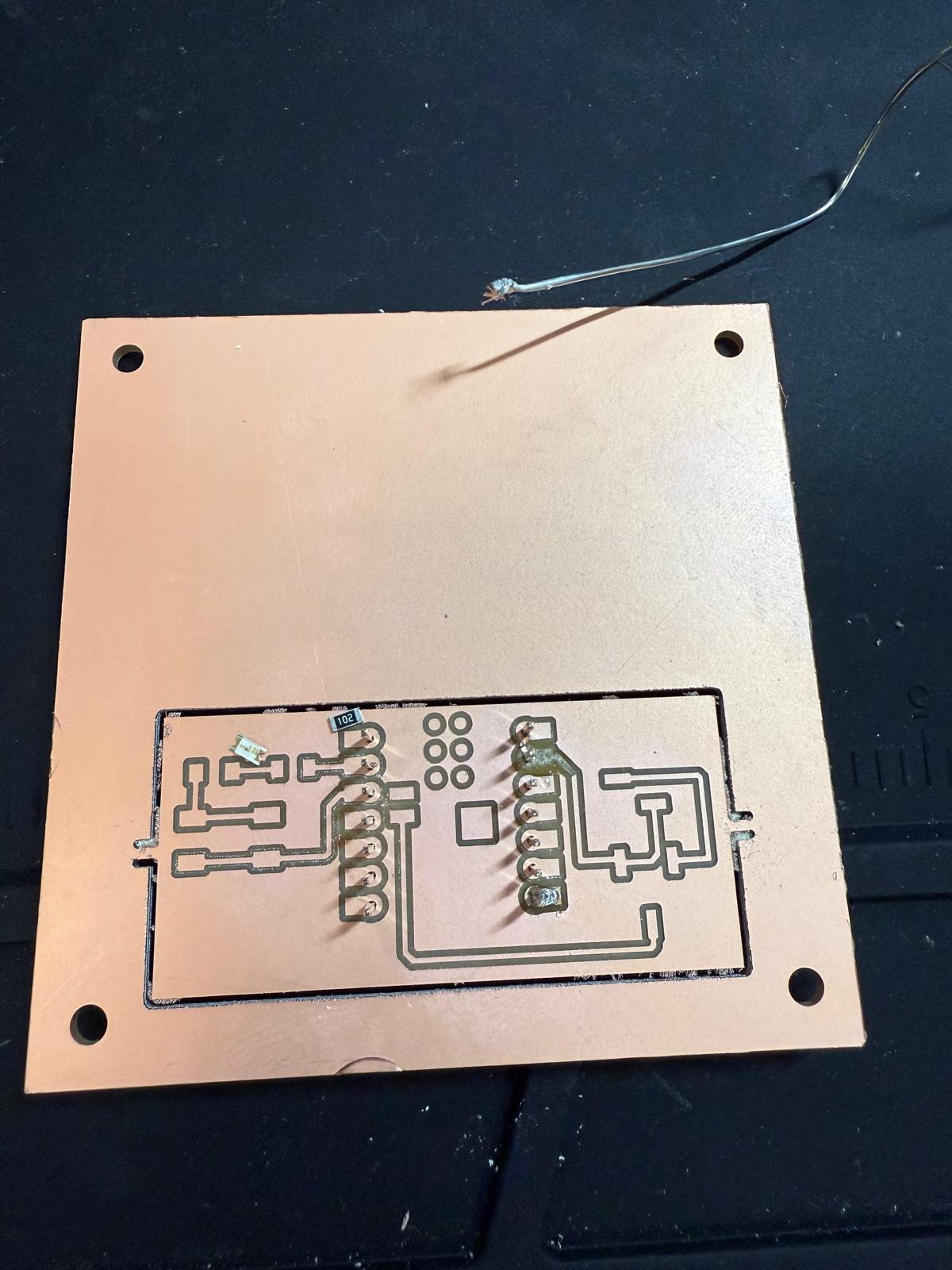
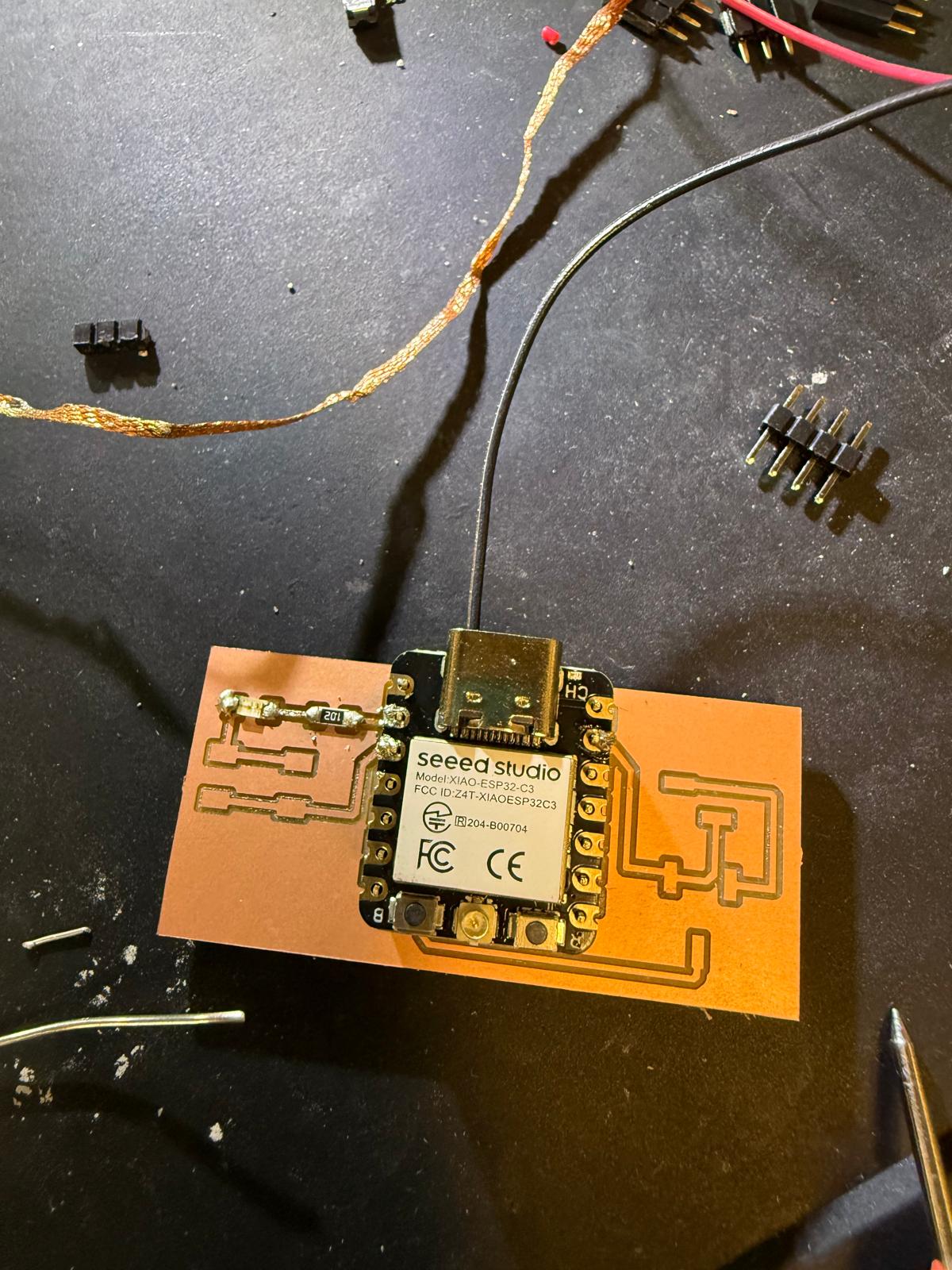
Soldering is challenging. When I went to desolder and accidentally let the solder removal tape cool, reheating it caused me to rip off a pad. This leads us to attempt 3.
Solder went everywhere....
After much soldering failure I decided to try to soldering the microcontroller directly to the board starting with the positive battery terminal. I was connected, but I applied too much force to check it and ripped the microcontroller off the board.
Off to a good start, or so I thought. However, what I didnt realize at time was that I had connected the diode to the ground.
Some sucess, I followed the directions on Seeed Studio. This was non-trivial and took a while to get the right COM port. I also didn’t understand at first that I needed to open the Serial Monitor to view any print statements. The light blinked!!!! So this was a win.
Then it stopped working....and I had no idea why.
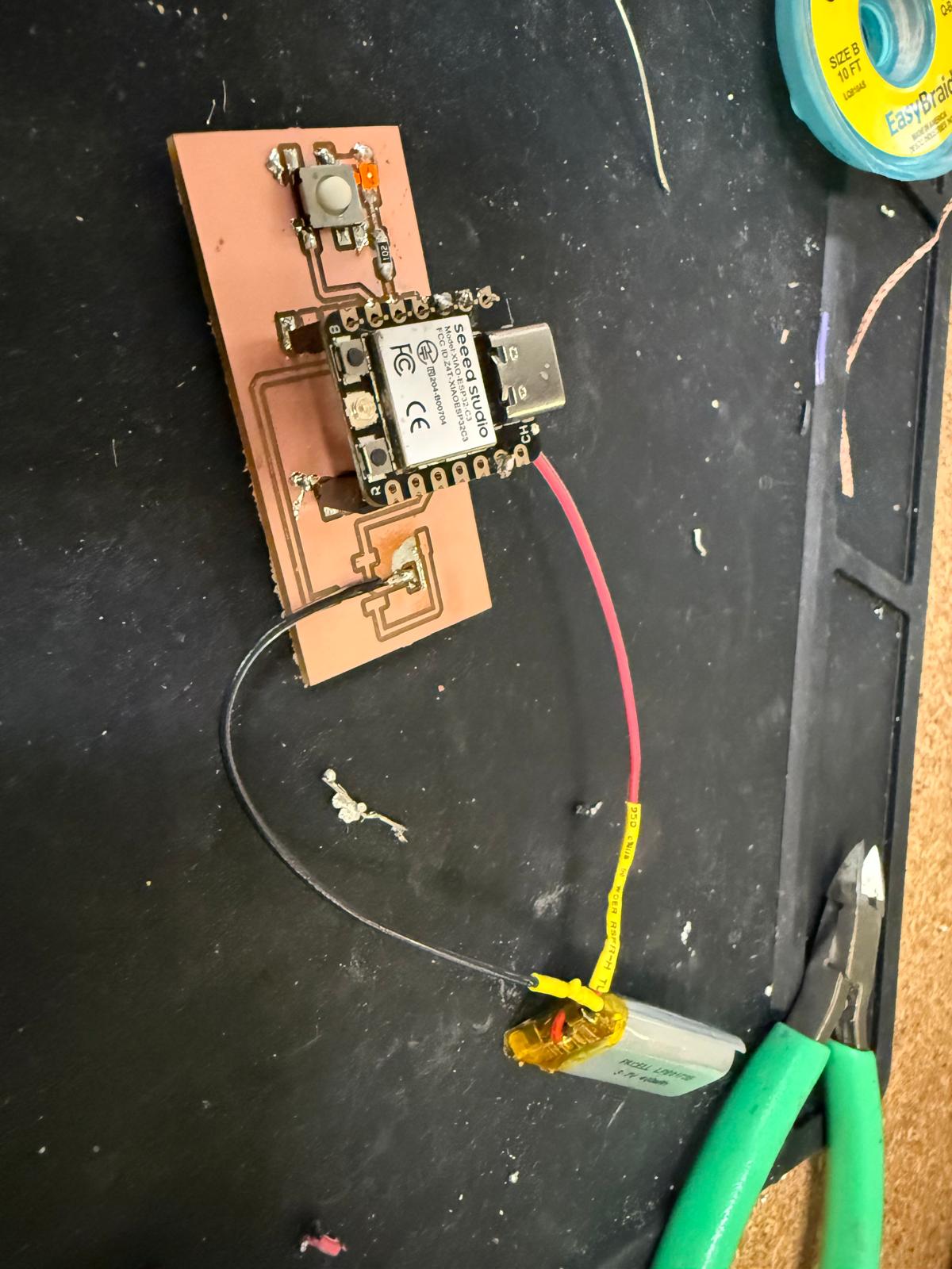
Well it turns out, everything is connected to ground. I tried to clean up some of the errant soldering on the button, diode, and ended up ripping the ground pad....
Starting a new board at 2100 before its due is not advisable, immediate soldering error.
So, I went back to Board 5 and rigged it, so it would work.