Assignment
The EECS group assignment is linked here.
This week, our task is:
- Measure something: add a sensor to a microcontroller board that you have designed and read it
Board
The Vision
This week, I focused on designing a board with input devices relevant to my final project. Specifically, I planned to use two types of input: one to detect motion and another to detect voice. For motion detection, I wanted my flower to respond when it senses human presence nearby. I decided to use a time-of-flight (ToF) distance sensor to detect motion in front of it. I briefly reviewed the datasheets for the available options and chose one that balanced range—about two meters—with cost. Ideally, I wanted a sensor in the low single-digit dollar range. Ultimately, I selected the VL53L0X. For voice detection, my goal was for the flower to recognize a joke. While no sensor can directly interpret humor, I planned to integrate a microphone (ICS-43434) with my ESP32-S3 microcontroller. The microphone would feed audio data into the microcontroller, which could then process it. The idea was for the microcontroller to periodically record short clips (every second or so, up to 10 seconds, depending on storage constraints) and send them over Wi-Fi as .wav files. These files could then be uploaded to a speech-to-text API or machine learning model to determine whether the audio contained a joke. This approach relies on cloud processing because local TinyML techniques are generally limited to detecting specific keywords. Detecting a joke is significantly more complex, and even advanced AI models do not always interpret humor reliably. While there are many potential points of failure in this plan, this represents the ideal workflow for achieving the desired functionality.
Some Notes
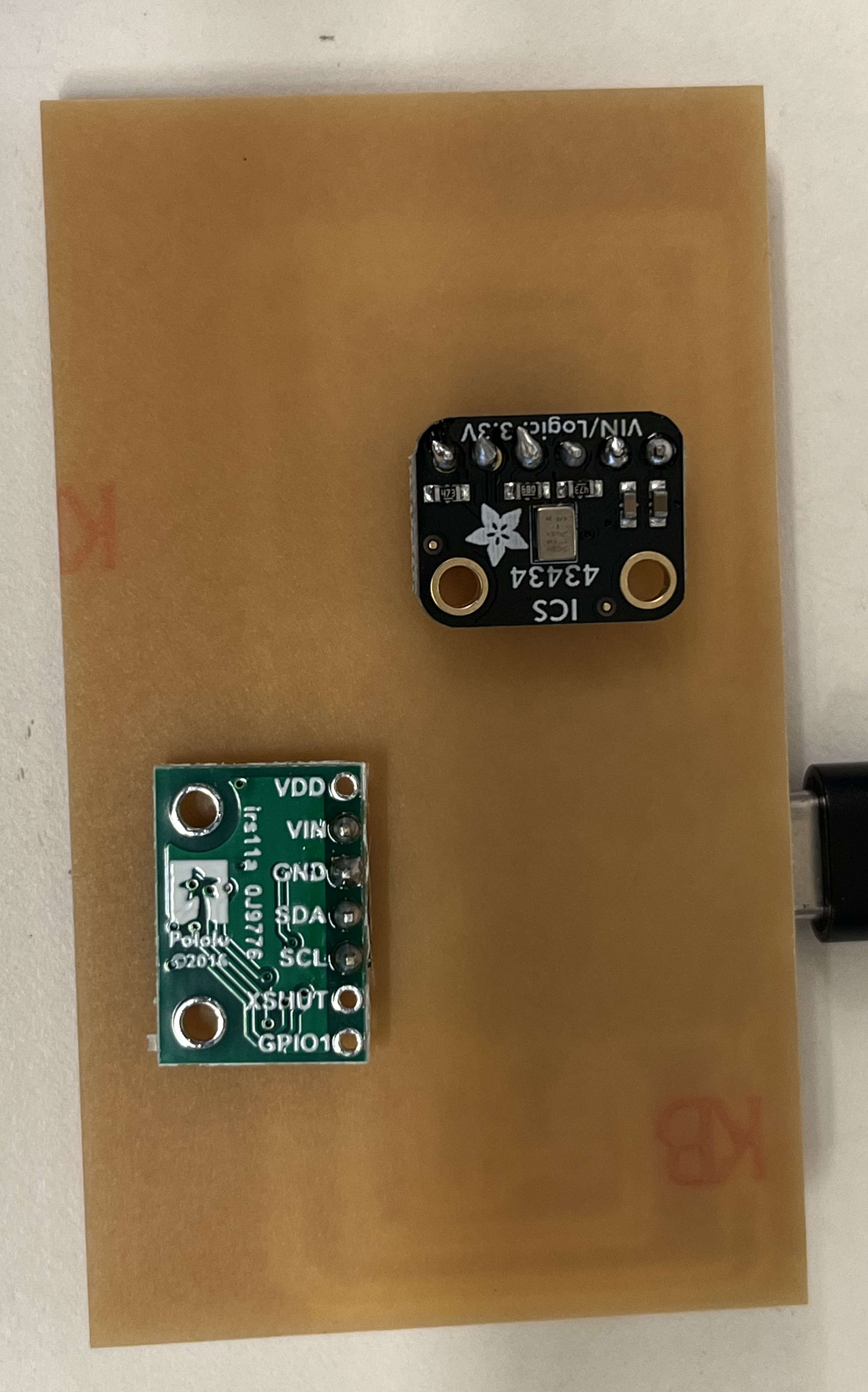
- Because the sensors I wanted to use were incredibly small in size, Anthony recommended that I use breakout modules, in which I used the VL53L0X and ICS-43434.
How to Make
- Make your schematic in Eagle.
- Use an ESP32-S3 as your microcontroller.
- Add an LED/1k Ohm resistor combination for debugging.
- Connect a 6-pin header set for ICS-43434:
- 3V to 3.3V
- GND and SEL to GND
- DOUT to D8
- LRCL to D7
- Connect a 4-pin header set for VL53L0X:
- Vin to 3.3V
- GND to GND
- SCL to SCL
- SDA to SDA
- Draw your layout in Eagle.
- I used 0 Ohm resistors for jumpers to make the geometry make sense.
- Mill your PCB, according to the instructions in Week 5’s page.
- Solder your board. I used wire solder for everything.
- The VL53L0X module is supposed to face sensor up.
- The ICS-43434 sensor is supposed to face sensor down (I did not know this).
- Program your board.
Eagle Design
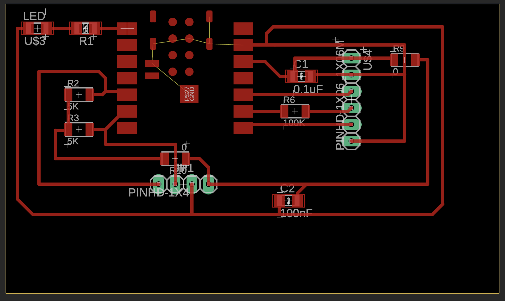
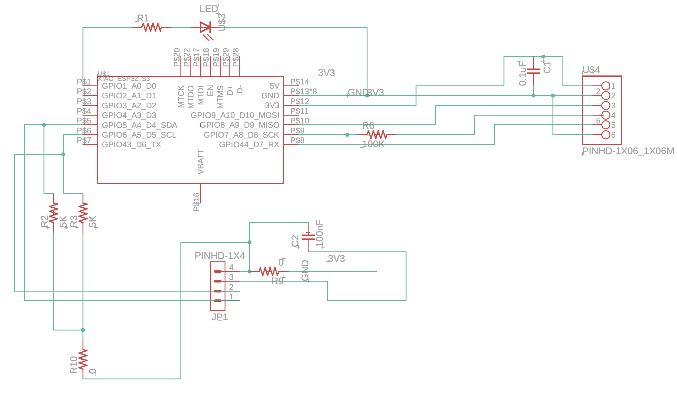
I had a previous design, which was my second board I made during the Week 4 electronics design unit. This week, I made several changes. For example, I replaced the sensor footprints with header pins, as I was now using breakout modules. I also realized that I had misread much of the documentation initially—I had placed resistors where they weren’t supposed to be—so I corrected those mistakes. After rereading the documentation, I added a 100 kΩ resistor, a 0.1 µF capacitor, a 100 nF capacitor, and 5 kΩ resistors, following the guidance (for purposes such as decoupling AC signals, pull-up resistors, etc.). At the time, I didn’t fully understand this, since I had never seen a breakout board in real life, but these extra components are often already included on the breakout boards, so adding them wasn’t strictly necessary. Most of these components, like resistors in parallel, could effectively be treated as open circuits if left unconnected, so it was fine to add them just in case; others I left open.
Soldering
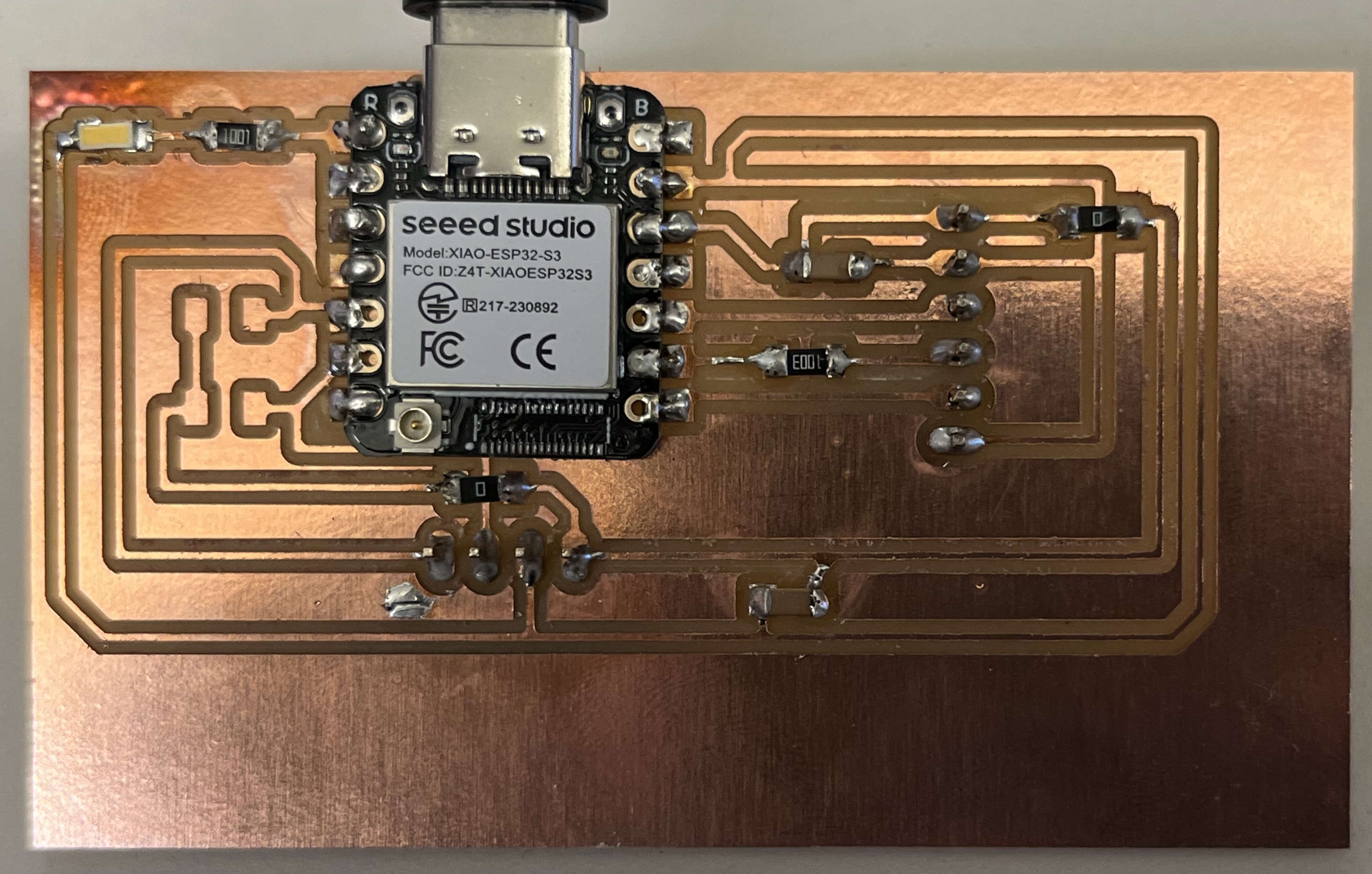
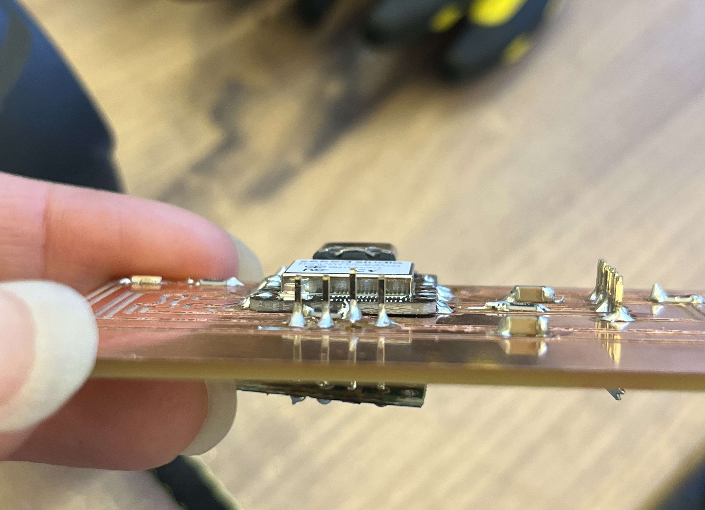
I made several mistakes while soldering, including installing the VL53L0X module upside down since I was kind of in a rush. I had to use hot air to remove it, which may have slightly damaged the board. I also learned that a short to an unused pin can still cause problems. A key lesson I learned is to check every connection as you go and use a multimeter to ensure there are no shorts to nearby pins.
Programming
What I struggled with the most was the time-of-flight sensor. It was particularly challenging because I had originally soldered it upside down. Even though the connections were technically correct, the sensor wasn’t facing the right way, which caused a huge problem. I tried to remove the module using a hot air soldering tool, but I think this may have caused some damage—it definitely melted the header pins, and there’s one spot where plastic seems deformed, where it shouldn’t be. In the end, I found myself trying to fix both software and hardware issues at the same time, which was not ideal. I could never really pinpoint what was going wrong. For example, when I was programming, I noticed a short, so I would go back and fix it, then try running the program again. Even after that, I ran into persistent issues. I spent about five hours trying to fix this, including using an I2C scan to detect devices, but no matter what I did, I couldn’t find the sensor. I even tried using my friend Eghosa’s code—she had successfully used a similar time-of-flight sensor—but her code couldn’t detect my sensor either. The expected device address for this sensor was something like 0x29, but mine was never found. Her sensor’s identiy was 0xeeaa, but mine showed up as 0xFFFF, which online searches suggested might indicate a communication error. I tried so many approaches—looking at prior students’ code, consulting online forums, scanning through every possible I²C address—but nothing worked. I still don’t know exactly what went wrong. It’s possible that I damaged the sensor while trying different code or soldering fixes. Regardless, I think the safest approach is to redesign my board. I’m hopeful that as I integrate it with the output devices in the coming weeks, the issues will become clearer. The next step would have been trying an oscilloscope, but since I'm still sick and it was quite late, I decided to leave it for the future.
            // to be ran in Arduino IDE
            // Prompt: i have a ics-43434 soldered to a xiao esp 32 s3. How do I get audio information and turn it into speech?
            #include
                #include

                #define I2S_WS  44  // Word Select (LRCLK)
                #define I2S_SD  7   // Serial Data
                #define I2S_SCK 8  // Serial Clock (BCLK)

                #define SAMPLE_RATE 16000
                #define I2S_PORT I2S_NUM_0
                #define BUFFER_LEN 512

                int32_t buffer[BUFFER_LEN];

                void setup() {
                  Serial.begin(115200);

                  i2s_config_t i2s_config = {
                    .mode = i2s_mode_t(I2S_MODE_MASTER | I2S_MODE_RX),
                    .sample_rate = SAMPLE_RATE,
                    .bits_per_sample = I2S_BITS_PER_SAMPLE_32BIT,
                    .channel_format = I2S_CHANNEL_FMT_ONLY_LEFT,
                    .communication_format = i2s_comm_format_t(I2S_COMM_FORMAT_I2S),
                    .intr_alloc_flags = ESP_INTR_FLAG_LEVEL1,
                    .dma_buf_count = 8,
                    .dma_buf_len = BUFFER_LEN,
                    .use_apll = false,
                  };

                  i2s_pin_config_t pin_config = {
                    .bck_io_num = I2S_SCK,
                    .ws_io_num = I2S_WS,
                    .data_out_num = I2S_PIN_NO_CHANGE,
                    .data_in_num = I2S_SD
                  };

                  i2s_driver_install(I2S_PORT, &i2s_config, 0, NULL);
                  i2s_set_pin(I2S_PORT, &pin_config);
                  i2s_set_clk(I2S_PORT, SAMPLE_RATE, I2S_BITS_PER_SAMPLE_32BIT, I2S_CHANNEL_MONO);

                  Serial.println("I2S microphone started!");
                }

                void loop() {
                  size_t bytesRead;
                  i2s_read(I2S_PORT, (void*)buffer, BUFFER_LEN * sizeof(int32_t), &bytesRead, portMAX_DELAY);

                  // Convert samples to 16-bit signed
                  int samples = bytesRead / 4;
                  for (int i = 0; i < samples; i++) {
                    int16_t s = buffer[i] >> 14;  // Downscale 32-bit to 16-bit
                    Serial.println(s); // You’ll see audio values here (use Plotter)
                  }
                }
        // to be ran in Python IDE
        // Prompt: how to save samples via serial as a .wav file?

        import serial
        import wave
        import struct
        import time

        # === CONFIGURATION ===
        SERIAL_PORT = "/dev/tty.usbmodem14101"  # change this for your computer
        BAUD_RATE = 115200
        SAMPLE_RATE = 16000       # must match your ESP32 code
        RECORD_SECONDS = 5        # how long to record
        OUTPUT_FILENAME = "output.wav"

        # === OPEN SERIAL PORT ===
        ser = serial.Serial(SERIAL_PORT, BAUD_RATE, timeout=1)
        time.sleep(2)  # give ESP32 time to reset

        # === OPEN WAV FILE ===
        wav_file = wave.open(OUTPUT_FILENAME, 'wb')
        wav_file.setnchannels(1)          # mono
        wav_file.setsampwidth(2)          # 16-bit samples
        wav_file.setframerate(SAMPLE_RATE)

        print(f"Recording {RECORD_SECONDS} seconds...")
        start = time.time()

        # === READ SAMPLES FROM SERIAL ===
        while (time.time() - start) < RECORD_SECONDS:
            try:
                line = ser.readline().decode('utf-8').strip()
                if line:
                    sample = int(line)
                    data = struct.pack('<h', sample) # 16-bit little-endian
                    wav_file.writeframesraw(data)
            except ValueError:
                pass  # skip malformed lines
            except KeyboardInterrupt:
                break

        print('Done recording.')
        wav_file.close()
        ser.close()
For the Future
Design Files
Project Considerations
- Camera for motion detection instead of time-of-flight
Acknowledgements
Resources linked above, Eghosa for letting me use her code to debug, Anthony as always!