Final project: Tiny DDR
I made Tiny Dance Dance Revolution. Tiny Dance Dance Revolution is just like normal Dance Dance Revolution except for a few key differences:
- It’s tiny.
- The only song you can play is J.S. Bach Invention No. 8.
- There is only one difficulty level, and it is Extremely Hard.
Here are the required question-answers:
What does it do?
It’s an interactive game console that plays music and displays a Dance Dance Revolution game. I claim that it is the tiniest Dance Dance Revolution machine that exists! It takes user input (pressure sensing -> pressed / unpressed) and displays when each arrow is pressed by illuminating a neopixel on that arrow pad as well as filling in the arrow receptor on the display, just as in regular DDR.
Who’s done what beforehand?
Dance Dance Revolution was invented in 1998 by Konami in Japan, and has gained a cult following. StepMania is an open-source version which was released in 2001; many “DDR consoles” (including the one in Walker Memorial, on campus) are in fact StepMania machines. There is a vibrant online community around DDR which produces tutorials for how to build a home DDR setup and populates a humongous crowdsourced database of downloadable game files.
There is a commercial tabletop DDR machine, the Dance Dance Revolution Classic Mini, which is hand-sized. There is also a toy which is finger-sized, but mine is still smaller, I checked :)
What sources did you use?
Throughout the process, I referenced demo code and circuit schematics (e.g. from Neil or Adafruit) for testing or developing different atomic components (e.g. capacitive touch, FSRs) which I link to when I describe their implementation. My most valuable resources were the CBA TAs: Quentin, Alfonso, Jake, Alan, and Dimitar (who I suppose was a student) in particular. I truly cannot overstate my gratitude for them! I learned so much from them and deeply appreciate their patience for me while I was in a truly frazzled state. I used Cursor for AI-assisted coding.
What did you design?
I designed the PCB, the 3D printed and laser cut housing, and the software for the game experience.
What materials and components were used?
Here is my bill of materials.
Where did they come from?
The class inventory and, when that failed, kind CBA friends.
How much did they cost?
They were free to me, but I estimate the total build cost to be around $30 (once again see the bill of materials).
What parts and systems were made?
I made the PCB, the 3D printed and laser cut housing, and the software for the game experience.
What tools and processes were used?
- 2D design: Used Fusion360 to make a DXF sketch for cutting aluminum on the Zund (with Alfonso’s help!). Used this same DXF to laser cut the arrow keys from clear acrylic. Also used pixilart to generate pixel art, which I converted into images for engraving on the arrow keys using the laser cutter.
- 3D design: Used Fusion360 to model the base plate, spacers, speaker grills, and “cups” to hole the arrow keys for 3D printing. Also used Fusion360 to model the laser cut housing for the OLED and speakers, which was laser cut on the XTools P2 out of black acrylic.
- additive fabrication: 3D printed parts for the base of the machine: base plate, spacers, speaker grills, “cups” to hold the arrow keys.
- subtractive fabrication: Carvera milling the PCB, laser cutting / engraving the housing and arrow pads, using the Zund to cut aluminum.
- electronics design: Used KiCad to prototype various PCBs.
- electronics production: Used the Carvera mill to mill single- and double-sided FR1 boards into PCBs, and sautered (and desautered) components.
- embedded microcontroller design, interfacing, and programming: Used a RP2040 as the computational “brain” of the machine – designed the PCB around it, wrote and deployed Arduino and MicroPython code, used both cores on the RP2040 to parallel process the OLED display and the audio.
- system integration and packaging: Designed all of the packaging in Fusion360 around the dimensions of the assembled PCB (including, for example, vertical clearance for the screw terminals on the bottom of the board). Designed the PCB with a notch for wire management and strain relieved wires with heat shrink and hot glue. Made sure board and OLED had screw holes which allowed for secure mounting into the final housing.
What questions were answered?
Can I make the world’s tiniest DDR machine? (yes) Is DDR still fun when it is tiny? (yes) Can Miranda make almost anything? (jury’s still out…)
What worked? What didn’t?
What worked: I’m really proud of how the machine turned out. Is it ready for the Market? Probably not. But, overall it looks very convincingly like a tiny DDR machine, the game which can be played is very much like real DDR, and it is fun to play. In fact, it handled many rounds of fairly rough play throughout the final project demo session!
What didn’t work: as much as I tried to make the capacitive sensing work, I was unable to get responsiveness on par with the FSRs. Neil gave me the helpful feedback that there may be some ways in software to improve this, which would definitely be valuable to try. Also, the keycaps I made significantly reduced the responsiveness of the system anyways. I tried to hackily fix this by taping a small folded piece of electric tape to the bottom of them so they only “press” on the FSR and not the surrounding components, but it was a crude and ultimately ineffective solution.
For the future, I would also like to finish up the housing (currently does not pass the shake or drop test) and implement scoring for the gameplay, as well as maybe a song selection menu, all of which I think would extend it to be even better.
How was it evaluated? (what is success for this project?)
Does it work / can you play it? (yes) Is it fun? (yes) Do people who know DDR recognize what it is? (yes) Is it responsive? (not really, when fully assembled anyway)
Nobody asked, but if it were me, I’d give myself a B+.
What are the implications?
The world has its new Tiniest DDR machine, which is obviously groundbreaking news for everyone. This was also an experiment in implementing DDR in the most low-compute way possible – no fancy graphics, not even real song files, just an array of pitches, 128x64 pixels on an OLED, four FSRs, 4 neopixels, a lot of prayers and hoping for the best. I honestly think it is a testament to DDR as a game that even in this most basic, first-principles form, the game is super fun to play. I also think that aesthetically, I achieved exactly what I wanted to, which is to make something which expresses the aesthetic Flavor of the medium of DIY electronics – hacky, beep boop, pixelated, rough around the (mostly perpendicular) edges but endearing nonetheless.
Here is the making of, in chronological order.
Conception
For my final project I will make a tiny (finger-sized) Dance Dance Revolution machine. That is, I want to make the thing which fills in the blanks to the following analogy:
Skateboarding : Tech decks (pictured below) = Dance Dance Revolution : ___.
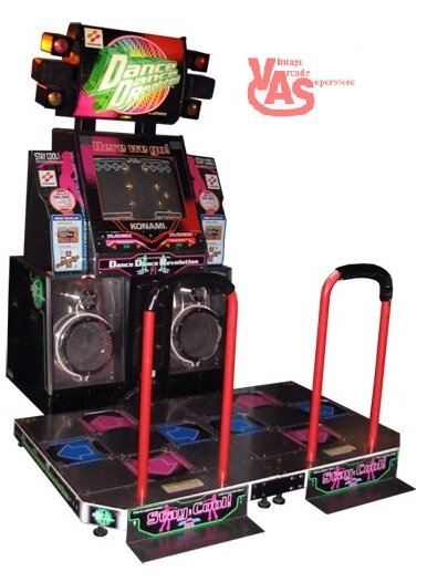
For the uninitiated, here is what a Dance Dance Revolution machine normally looks like:
And here’s some videos of me and Kye playing the game, for research of course (we are probably right about at the skill floor).
Here’s a video of someone who is closer to the skill ceiling.
September 22: QPAD prototype
For my Week 3 individual project I used the QPAD to prototype a very barebones version of the code for this project, where arrows are randomly generated below the screen and float upwards across the display. I loaded this onto the QPAD and implemented some simple visual feedback for the directional touch button presses.
September 25: custom DDR arrow icons
When I tried to make receptors (the hollow arrows at the top of the DDR screen) using the same concatenated rectangle and triangle I had before, I had a crucial realization:
They’re ugly.
Specifically they are ugly because the aspect ratio of the arrows is not square, so that the up/down arrows take up more vertical room than the left/right arrows. This motivated me to import the iconic DDR arrow icon (see below) into my code, which is square by design.

After doing some research I found that importing images into Arduino requires converting them into bitmaps. I found a tool called image2cpp which does the conversion. Since the resolution of my display (128px by 64px) is smaller than any of the DDR arrow images I was able to find online, I decided to use a pixel art tool to draw my own, using an image of a pixelated DDR arrow for reference.
![]()
I drew three square arrow sizes: 16px, 24px, and 30px, converted them to byte arrays, and put them all onto the (simulated) display at once just to get a sense of which one I liked best. I also left in one of the original rectangle + triangle arrows for size reference. In the below image, the arrows are (from left to right): 16px, 24px, 30px, original rectangle + triangle arrow.
![]()
The 30px is the most visually striking and takes up the screen space the best, but feels too big – there is not much room to display incoming arrows before they need to be pressed since the receptor would take up half the height of the screen.
The 16px would allow for a 2-player version, since 8 of them can fit across the width of the screen (unlike the other two sizes). If I have time I would love to implement the multiplayer (competitive) version, but for simplicity I decided to start with a single-player design, and for that design these icons feel too small.
So, I decided to go for the 24px icons.
September 26: DDR machine sketching and scoping
In order to scope out the project I triangulated some reference photos of real-life DDR machines, like the one below, to draw out the minimum set of features necessary for my tiny DDR machine.
In the process I encountered a commercial tabletop DDR machine, the Dance Dance Revolution Classic Mini, which is hand-sized. My vision is to make an even smaller one, though. I wonder if I can lay claim to World’s Smallest DDR Machine…
Here is a quick sketch I did of my vision for the final product:
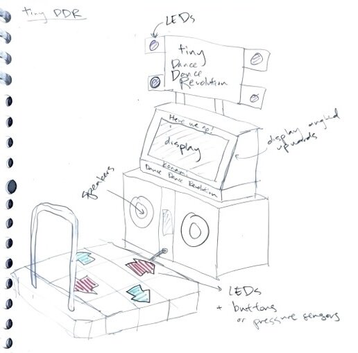
Some other miscellaneous thoughts I had: - This Arduino speaker set would be so perfect aesthetically… it’s not in the class inventory, but I might just buy it for myself as a treat. - I found some interesting 3D-printable files for DDR arrow keycaps. This one is simple, just one piece I could print pretty quickly using transparent filament to allow the LEDs to shine through the entire keycap. This one is more elaborate, involving multiple parts that fit together so that only the arrow is transparent, which is more faithful to real DDR pads. I have extra mechanical keyboard switches at home that I could use for this project as well. However, I’m not sure if the interaction will feel quite right, as the keyboard switches have quite a depth to their pressing range, whereas the DDR pads seem to be pressure sensing and thus don’t depress when stepped on. There are shallower switches in the class inventory which may be a nice in-between, but I’d have to figure out how to CAD the arrows on top of them myself.
Weeks 5&6: DDR arrow pad PCB prototype
In week 5 I designed a multi-layer PCB which uses mutual capacitance sensing and flexures to detect when an arrow is pressed. In week6 I fabricated this PCB and ended up with a beautiful working prototype.
Week 8: timing logic for arrow display
In week 8 I wrote a little pipeline which will automatically parse simfiles (open-source DDR files, containing for example the .mp3 of the song, the arrow directions and on which beats they are meant to be pressed, some image assets) into a text file of millisecond timestamps and arrow directions. I wrote Arduino code to read this in and print the arrow directions to the Serial Monitor at the correct time, so that I can implement the scoring logic (which is based on millisecond deviation from the desired arrow timing) later.
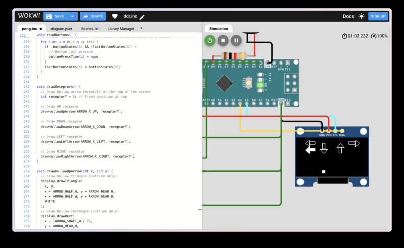
Week 9: OLED display + speakers PCB
In week 9 I fabbed a little board which connects to a display and two speakers (through an amp), so I can play audio and display the arrows at the same time. My plan is for this board to connect to the arrow board via I2C.
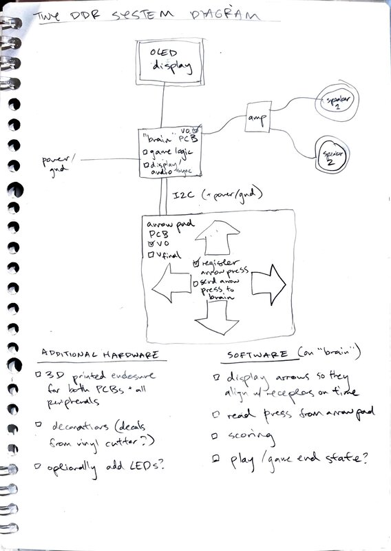
Week 11: the beginning of the end
Here is a system diagram of my tiny DDR system.
Remaining tasks, with tentative deadlines
EE
- [by Wednesday, November 26] Connect arrow pad and brain boards with I2C. Send arrow pad presses to brain board. Read the arrow presses from the brain board and print them to the Serial Monitor.
- [by Wednesday, November 26] Redesign the arrow pad board to be even smaller, and send it to a PCB house for manufacturing (to hopefully make the mutual capacitance stuff more reactive!)
Software
- [by Wednesday, December 3] Display arrows so they align with the receptors on time.
- [by Wednesday, December 3] Implement scoring based on the timestamps of the arrow pad presses.
- [by Wednesday, December 10] Implement play / game end states.
Hardware
- [by Wednesday, December 3] Print V0 of the the 3D printed enclosure for the machine.
- [by Wednesday, December 10] Finalize the 3D printed enclosure for the machine, and have it assembled.
The final week! (December 7-14)
First, I started by trying to get the arrow input to work.
ddr_mutualcap_v2
First, I tried to redo the mutual capacitance input board I made in week6 with a thinner substrate between the capacitive plates.
Here was my sketch for the board:
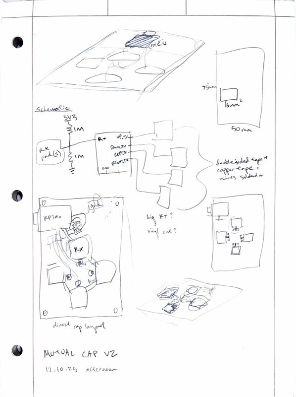
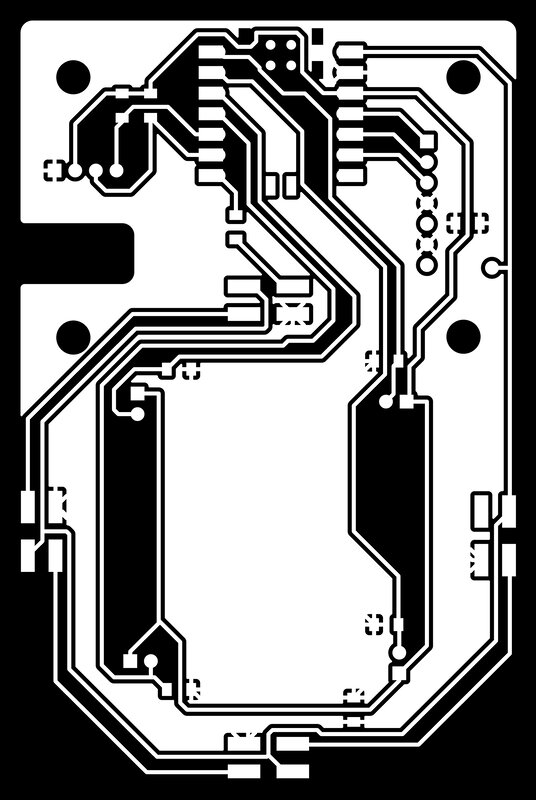
Here were my traces and edge cuts:
I milled it on single-sided FR1 and used double sided VHB tape as the medium between copper tape and the plate on the PCT itself.
.zip archive of Kicad files here.
This was much less susceptible than my previous board to interference from, e.g., moving my finger around on the bottom of the board. But, it was still not very reactive, and did not work at all when I pressed on it with an insulated substrate (in my case, the black rubber table runners in the electronics lab).
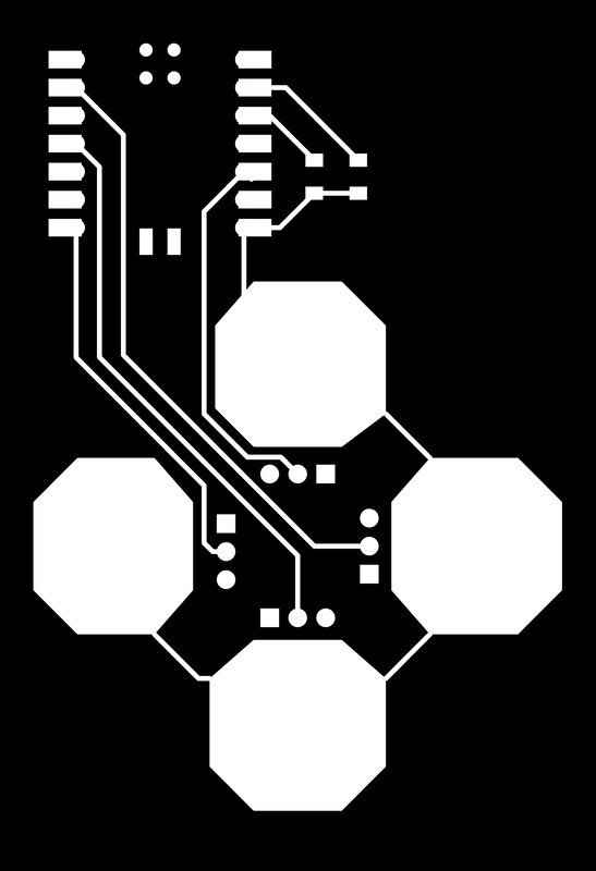
ddr_pads_v3
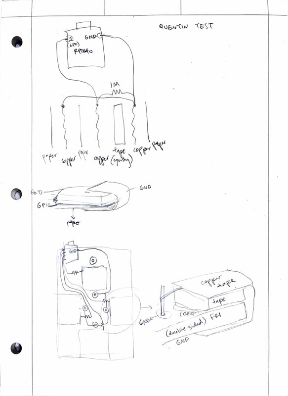
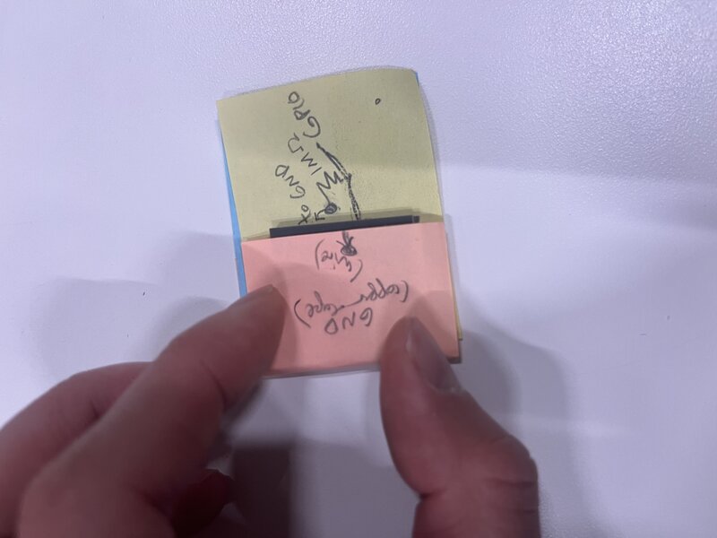
Quentin and I did an experiment to see if we could quickly prototype a mutual capacitance system where the ground plane wraps (like a taco) around the receiver plane which is connected to the GPIO. we were able to get it working, with double sided VHB tape as the substrate between pads:
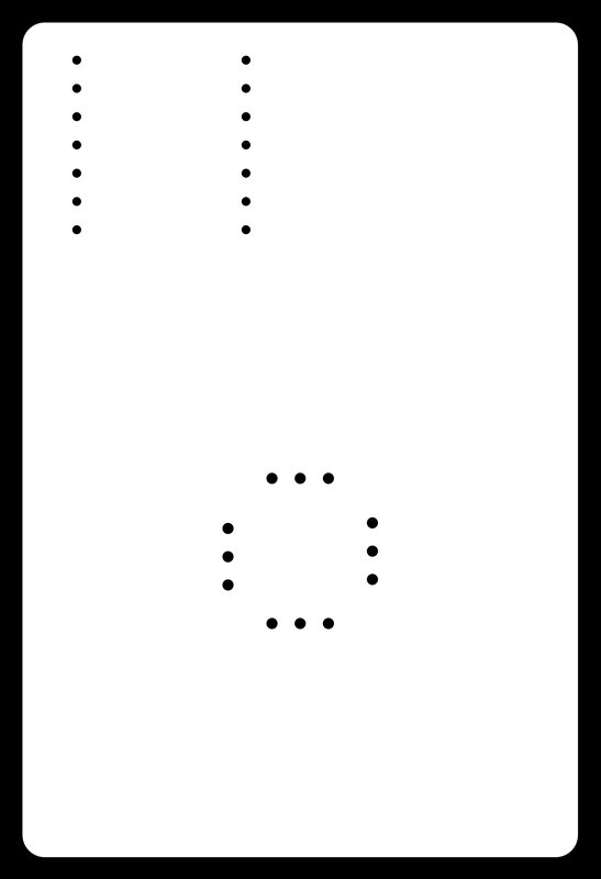
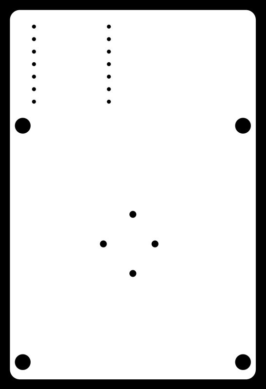
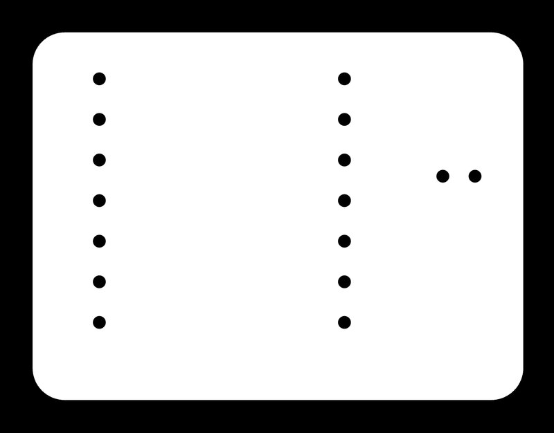
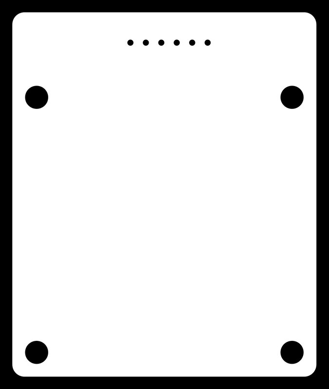
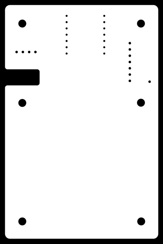
I designed a board based on this experiment, and milled it. To help me visualize the layers I made a simple paper prototype, which I found very helpful for doing spatial reasoning:
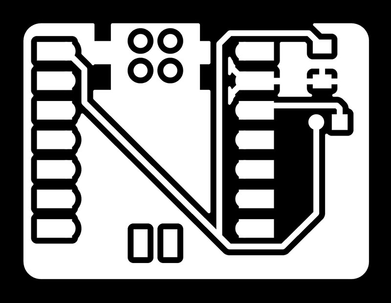
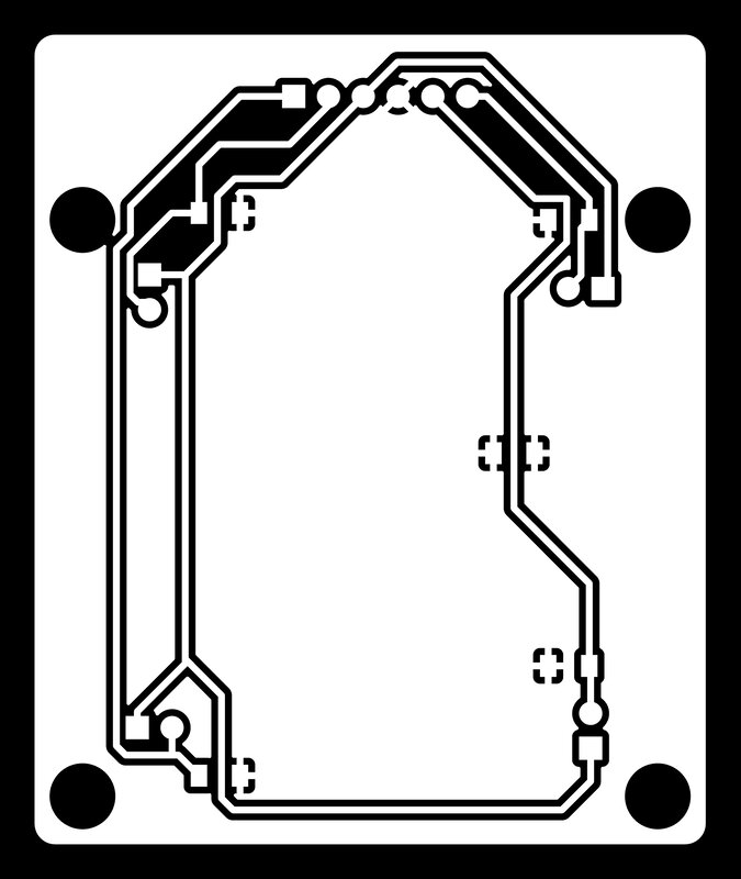
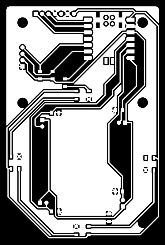
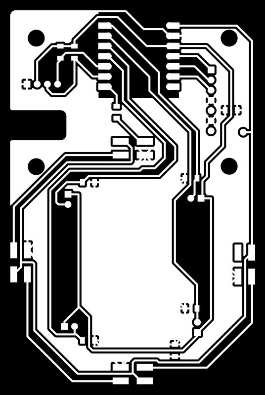
Here were my traces and edge cuts:
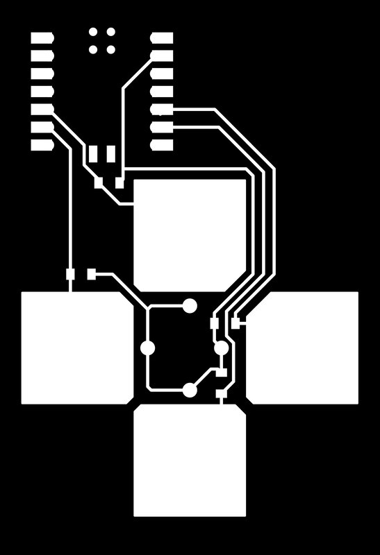
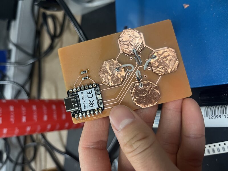
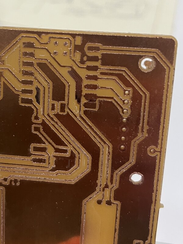
And here was the final board:
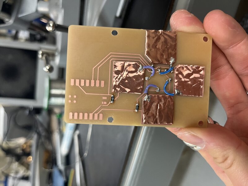
.zip archive of Kicad files here.
As a test I flashed Neil’s steptime code, which required me to setup MicroPython on the RP2040 using Thonny.
I still found this board to be not as reactive as I would like, and I was running out of time to innovate on it given my limited experience with EE. So, in the name of Supply-Side Time Management, I went to my fallback option: force-sensitive resistors.
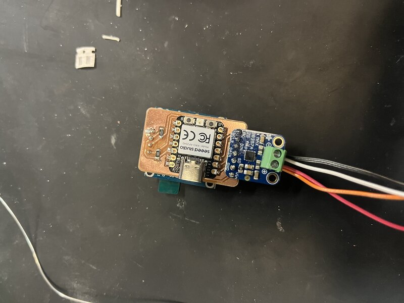
fsr_test
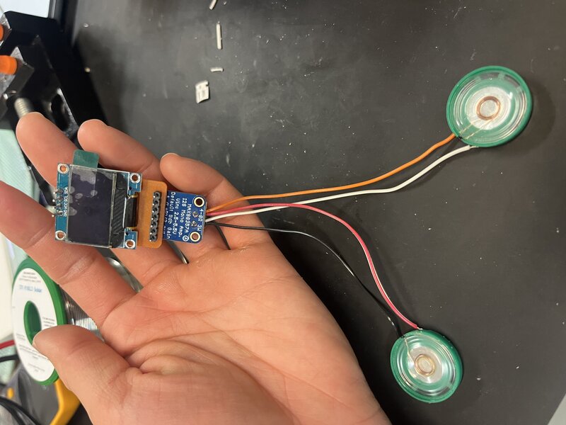
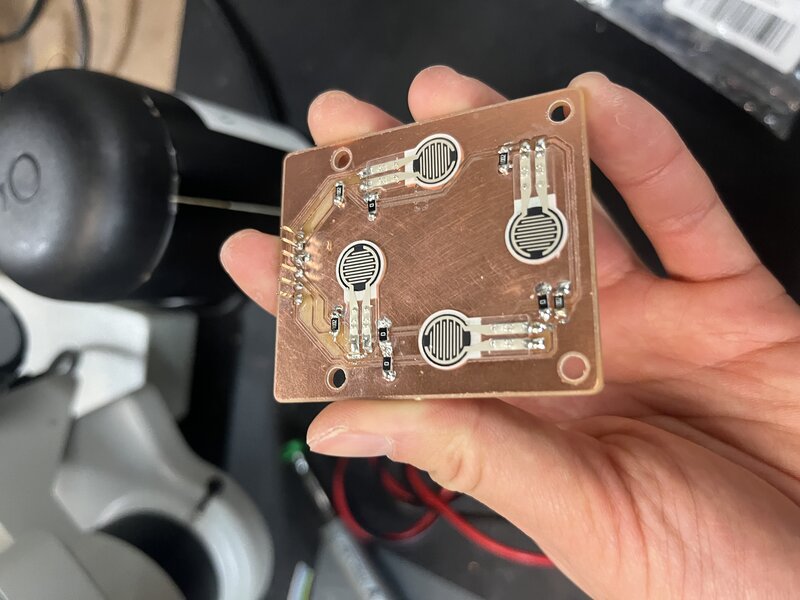
Following the wiring from this Adafruit tutorial, I milled a test board to try out the FSRs.
The board came out perfectly tiny and adorable, and the FSRs worked great.
.zip archive of Kicad files here.
fsr_board
The natural next step was to design a board with 4 FSRs.
Here was the final board:
.zip archive of Kicad files here.
It works, but as I began to think about assembly, I realized that it makes more sense for the OLED to be detached from the screen (via jumper wires), rather than having the main PCB attached behind the OLED as was my initial idea. In this case, the entire board could be milled in one piece, instead of needing a separate board for the arrow pads (FSRs) and the brains (RP2040). Also, Quentin said: “Adding neopixels will make your project look 1000% cooler.” And unfortunately, as always, he was right.
unified_board
I designed and milled the unified board:

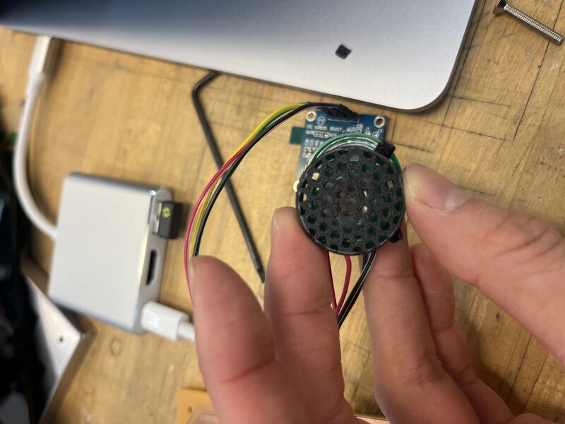
And, when soldering, discovered a few issues. First, the pins for my amp were backwards, so I attached it to the backside of the board instead, which I ended up liking better anyway. Second, and more important, the neopixels were impossible to solder. The legs were folded underneath and the pads in the fab library footprint were so small that they went only under the neopixel. I tried using solder paste and a heat gun, but was having a lot of trouble. Jake came to try to help me, and together we barbecued a neopixel:
![]()
Jake advised me to edit the neopixel footprint in Kicad to make them bigger, and to bend their legs out before soldering them on the board so I could solder them from the sides as usual for surface mount parts. While examining my circuit Jake also noticed that my FSRs were connected to digital, not analog pins – it was time for another PCB redesign.
I redesigned the PCB to fix the FSR wiring and enlarged the neopixel pads substantially.
While milling this board, I didn’t sufficiently clamp / double sided tape my stock down, and parts of the board were incompletely milled.
Nik showed me how to use an online G code viewer to step through what the G code is doing, and remove all unnecessary lines so that the G code goes straight to milling only the problem area. I deleted a lot of the lines of the G code and we tried to re-mill these areas deeper (also changing the max depth setting in mods), but to no avail.
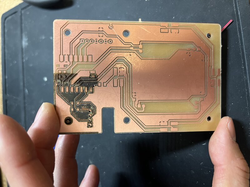
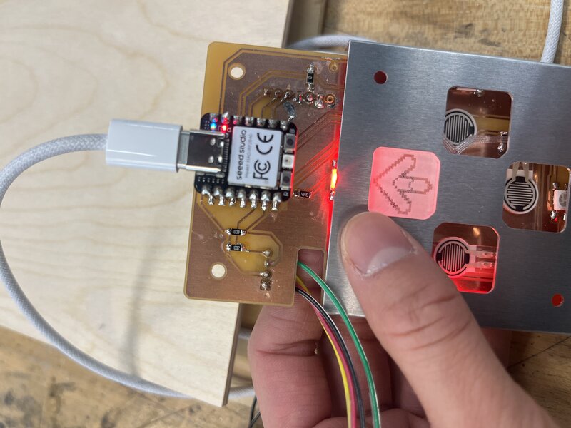
I tried again to mill the board and somehow an entire corner was left unmilled. Alan very kindly helped fix it using the laser, but by that time I had already re-milled a third, successful board. But this board looks pretty sick, and surprisingly is connected in all the right places:
The first thing I did when I milled the new board was to test the neopixels, since I’d never worked with them before.
![]()
Then, shortly after, I shorted power to ground. Dimitar showed me that the pads on bottom of the Xiao are connected to ground, even though they’re not labelled as such in the fab footprint library.
I decided to work around this by levitating the RP2040 onto some headers so it could A) be easily swapped out if it shorted again and B) not make contact with anywhere on the board other than the pins. In order to get mods to mill the through holes in the fab footprint for the RP2040, I had to enlarge them in Kicad.

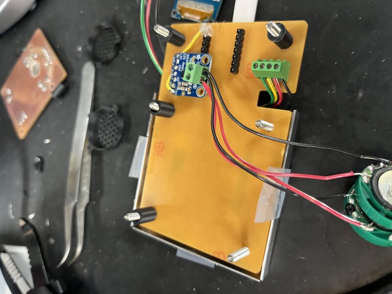
Here is the final, assembled board with all peripherals.
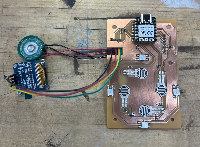
.zip archive of Kicad files here.
Assembly
Note: for all of the assembly, I had a lot of hand-drawn drawings but I’ve tragically lost my notebook, so I don’t have images of them to put here.
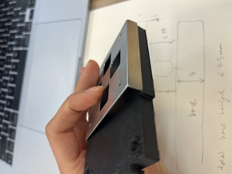
Alfonso helped me Zund the metal part to go around the arrows, which I think really elevated the whole look.
![]()
I tried several iterations of the 3d printed base. The first one was too large for the metal part. I ended up going with a design that is skinny all around so that I have plenty of clearance.
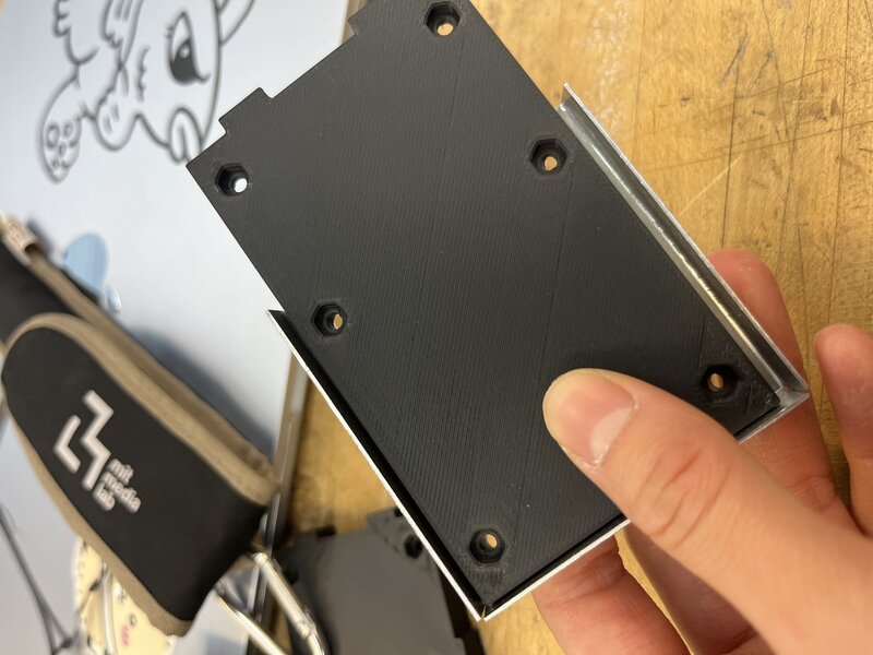
I also 3D printed some spacers, 10mm and 12mm. The hole in the middle was 3.2mm, which I later realized was too small – it worked if I threaded the screw through it, but it was a tight fit. I later settled on using 10mm tall spacers with 4mm hole diameter, .3mf file here.
Here’s a view of the base and the spacers underneath the PCB – note the cutout to allow maximal clearance for the electronics beneath the PCB.
![]()
I designed a little speaker grill following this Youtube tutorial; .3mf file here:
Matti helped me laser cut some arrow keys from clear acrylic. I designed a printed a little cup for them to sit in, so they wouldn’t fall out of the DDR board if it were to be inverted (.3mf here):
![]()
I also had many failures trying to print these successfully. I had to tune the 3D printer to change the speed slower (around 85%), and adjust the nozzle and bed temperature higher for the Polylite PC filament, to 275C for the nozzle and 115C for the bed.
I re-cut the arrows with the inverse engraving (image here), and found that it diffused the light much better:
Next, I learned the hard way that one must kerf test their material before attempting a press fit. I kerf tested the black acrylic, and then had to kerf test it again when I switched to black acrylic of a different thickness – I learned from Ceci that acrylic shrinks when heated, so the kerf isn’t consistent.
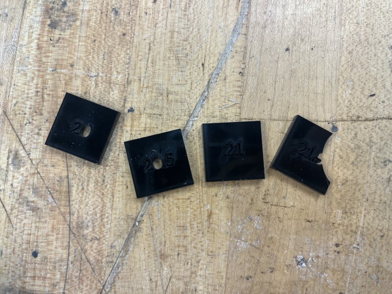
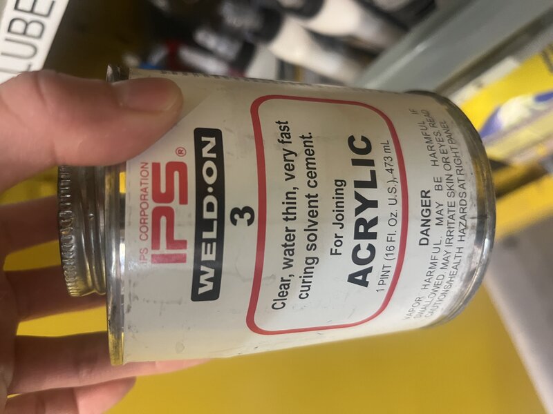
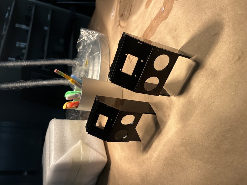
Eventually after much iteration I was able to laser cut and press fit these houses, which I secured to each other with Acrylic Weld-On, which worked like a charm.
Each house was comprised of a top piece, two side pieces, a panel for the OLED, and a panel for the speakers.
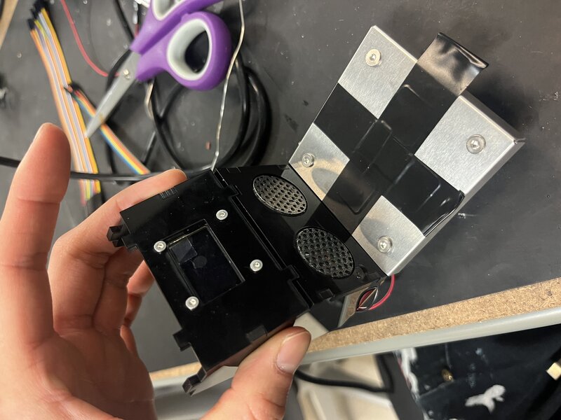
The final assembly involved sandwiching the metal piece, arrow keys, PCB, and spacers in that order, “belly up”. I then screwed on the base with nuts from the other side, and placed the house on top.
Coding
All my final code is in this Github repository.
My initial vision was to use the open-source game archives from this crowdsourced database, but when I downloaded a song off of this archive and tried to play its audio through my itty bitty speakers it sounded like this:
… absolute garbage. So, I pivoted – I thought the sound of Neil’s MAX98357 demo was pretty aesthetically appropriate for this project, so instead of taking audio from an existing DDR game archive I decided to invent the game sequence from this series of pitches.
Spiral 1
With the help of AI, I wrote a Python script to generate the arrow sequence for J.S. Bach Invention No. 8. Here is the Cursor chat history for this script. Here is the file.
I made the main .ino file play Bach and show the arrow sequence at the same time. Here is the chat history for this script. Initially, when the code for the OLED display was added to the same loop as the audio pitch playing, the audio had slight latency between tones, so that two adjacent and identical tones registered as two separate notes rather than one held note. It was at this point that I recalled what Jake had told me – that the OLED is slow, but the RP2040 has two cores, and I can make one of them exclusively for the OLED.
Here was the final result:
Spiral 2
For the next spiral, I reused some old code to threshold the FSRs so the LEDs light up when an arrow is pressed. I also made the arrows pass from the bottom to the top of the screen, with unfilled “receptors” at the top.
I keep a buffer of the arrows which are on the screen, and when a key is pressed I delete the highest (greatest y-value) arrow in that direction as well as display the receptor as filled / white. Chat history here.
Spiral 3
For the final spiral, I added a start and end game state, so the game doesn’t start immediately when the device is plugged in. Before the game starts, it says “tiny ddr - press any key 2 start” and then at the end it says “the end”. When the game is started, the user sees “ready?” and then “here we go!”, which is a reference to how DDR games start (spoiler: with these same two lines of dialogue). Chat history here.
I wanted to also implement scoring, but I ran out of time. But, I had
thought through how I’d do it. Say we have some constant
PRESSED_ARROW_SCORE score increment which is awarded to the
user for simply pressing the arrow of the correct direction (there
exists an arrow on the screen which is of the direction which was
pressed). Since in the previous spiral I stored the y-value of each
arrow on the screen, and compute which arrow to delete (the one closest
to the top of the screen), I can compute the score as follows:
score = PRESSED_ARROW_SCORE - abs(receptor_yval - arrow_yval).
That way, the score is highest if the arrow is pressed perfectly on time
(when it aligns perfectly with the receptor), but nonzero if an arrow
exists. I could also implement a penalty for pressing a direction for
which there is no arrow of that direction on the screen, if I wanted to
be mean. I regret not having time to implement scoring, but I felt it
was auxiliary to the main game mechanics, so in the name of supply side
time management I hustled upstairs to set up for the final project
demo…