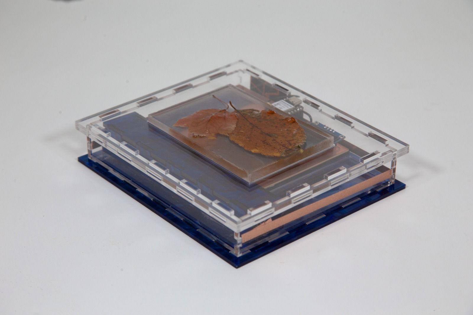
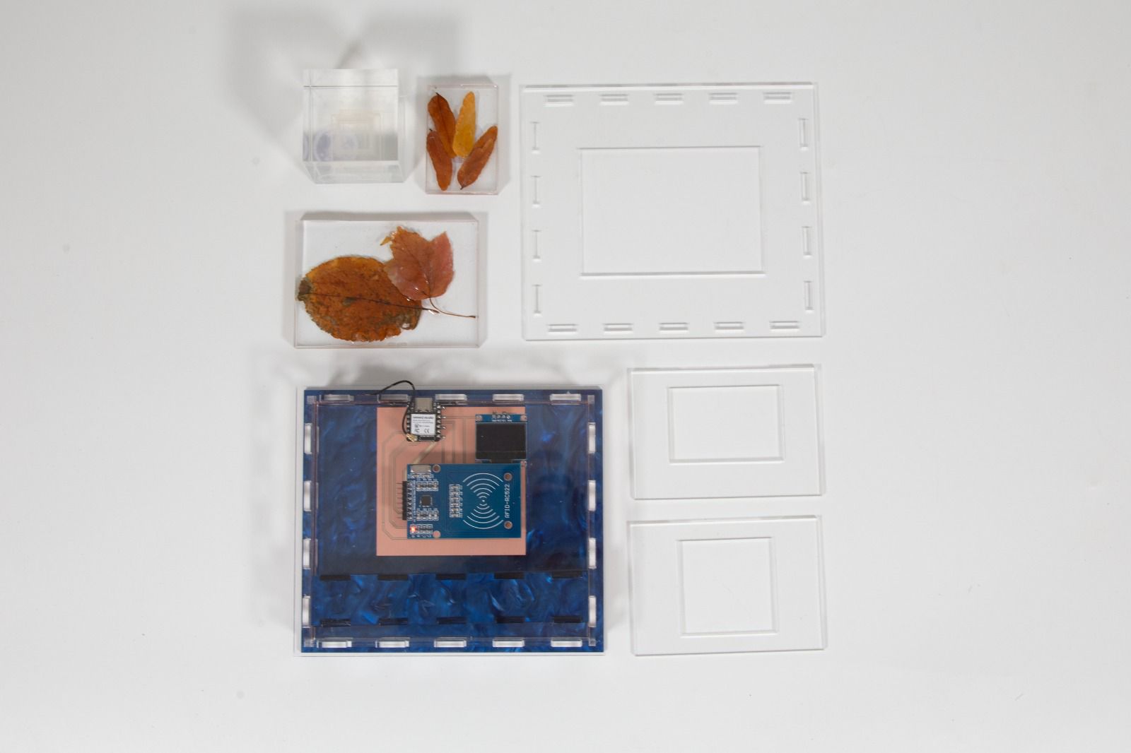
Final Result
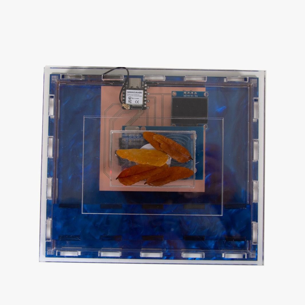
Here's some photos and footage of the final product actually working, and the process of production will be on next section:
Project Concept
System Diagram
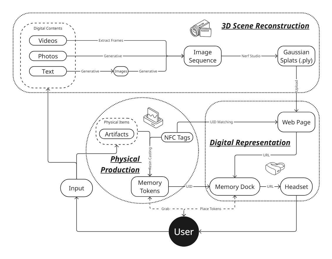
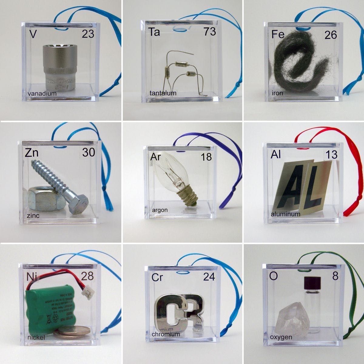
For my final project, I propose to build a table-top project titled Home Again. The setup will feature small physical objects in the form of cassette tapes. Each cassette will be linked to a specific virtual scene.
When a participant picks up a cassette and places it on the table, an image recognition or sensing mechanism will detect it and trigger a VR headset to load a corresponding scene. These scenes will be drawn from my collection of 3D-scanned environments, prepared both as photogrammetry meshes and as Gaussian splats.
Midterm Check
To-Do List:
-
☐ Make the circuit board for the Memory Dock
- ☐ Connect the XIAO ESP32-S3 to the RFID reader and retrieve the UID
- ☐ Enable the XIAO ESP32-S3 to communicate with my headset over Wi-Fi
- ☐ Write helper scripts to open different webpage URLs based on the UID
-
☐ Create sample tokens
- ☐ Cast NFC tags together with physical objects (e.g., leaves)
- ☐ Or use an acrylic box to seal them
- ☐ Design cases for the Memory Dock
- ☐ 3D scene reconstruction (sourced from another class)
Schedule
| Week | Task |
|---|---|
| week 12 networking and communications | Make the circuit board for the Memory Dock |
| week 13 interface and application programming | Design cases for the Memory Dock |
| week 14 wildcard week | Create sample tokens |
| week 15 final assignments and orders |
Production Process
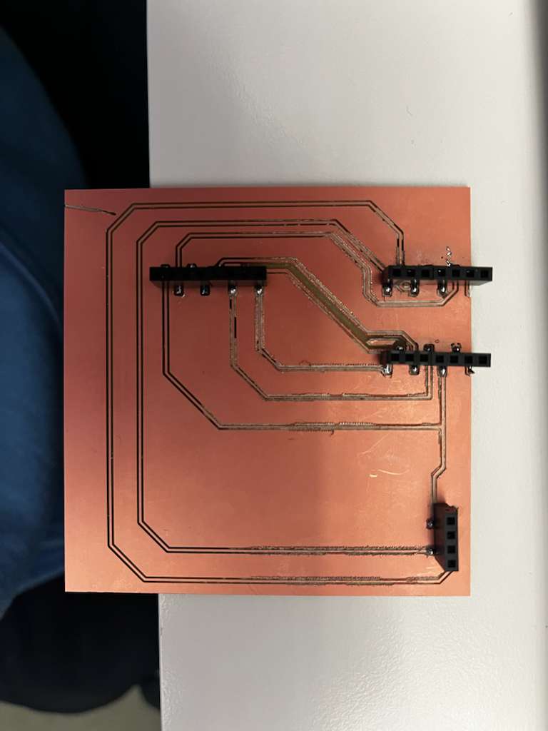
Breadboard prototyping
First and foremost, from the networking week, I was able to get a working final prototype for my project, but due to the fact that the copper board didn't get milled cleanly, I was only able to make my prototype work on a breadboard. But still, I was able to turn the XIAO ESP32-S3 into a tiny HTTP server and map different RFID tags to specific webpage URLs. The Arduino code is shown below:
tiny server code (click to see the code)
#include <WiFi.h>
#include <WebServer.h>
#include <SPI.h>
#include <MFRC522.h>
#include <Wire.h>
#include <Adafruit_GFX.h>
#include <Adafruit_SSD1306.h>

// ================== WIFI CONFIG ==================
const char* WIFI_SSID     = "your wifi ssid";      // <-- EDIT
const char* WIFI_PASSWORD = "your passcode";  // <-- EDIT

WebServer server(80);

// ================== PIN MAPPING (YOUR SETUP) ==================
constexpr uint8_t PIN_SS_RFID  = 44;   // RC522 SDA / SS
constexpr uint8_t PIN_RST_RFID = 2;    // RC522 RST

constexpr uint8_t PIN_SCK      = 7;    // SPI SCK
constexpr uint8_t PIN_MISO     = 8;    // SPI MISO
constexpr uint8_t PIN_MOSI     = 9;    // SPI MOSI

// I2C pins for OLED
constexpr uint8_t PIN_SDA_OLED = 5;    // SDA
constexpr uint8_t PIN_SCL_OLED = 6;    // SCL

// [Code continues - see full version in original document]
result


and the actual pin connection is listed as following:
| Xiao | RC522 | OLED |
|---|---|---|
| GPIO2 | RST | |
| GPIO5/ SDA | SDA | |
| GPIO6/ SCL | SCL | |
| GND | GND | GND |
| 3V3 | 3.3V | VCC |
| GPIO9/ MOSI | MOSI | |
| GPIO8/ MISO | MISO | |
| GPIO7/ SCK | SCK | |
| GPIO44/ RX | SDA |
So let's say if you want to update and add more links to it, or you need to connect to a new wifi:
There are only two places you need to edit:
WiFi credentials
const char* WIFI_SSID     = "YOUR_WIFI_SSID";
const char* WIFI_PASSWORD = "YOUR_WIFI_PASSWORD";
UID → Label → URL mapping
struct TagMapping {
  const char* uid;    // UPPERCASE hex UID, e.g. "04986F2A"
  const char* label;  // Human-readable name for OLED + web
  const char* url;    // Full URL to open
};

TagMapping tagMap[] = {
  // Fill with YOUR tags:
  // {"04986F2A", "Arboretum", "https://example.com/arboretum"},
  // {"A1B2C3D4", "Cemetery",  "https://example.com/cemetery"},
};
You'll copy UIDs from Serial Monitor, then hand-type labels + URLs.
Demo Video of it working
Token Production
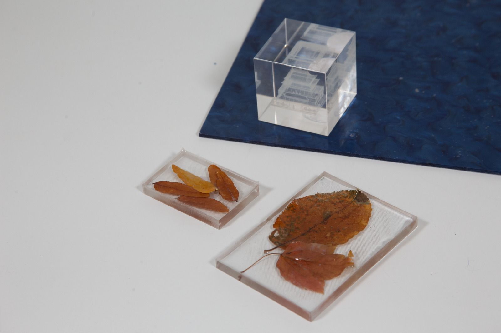
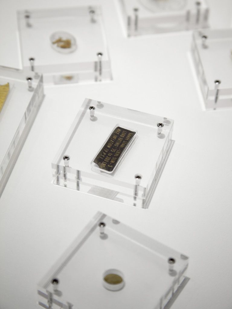
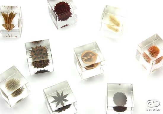
For my final project, I created two types of tokens: one resin-casted and one glass-engraved from wildcard week.
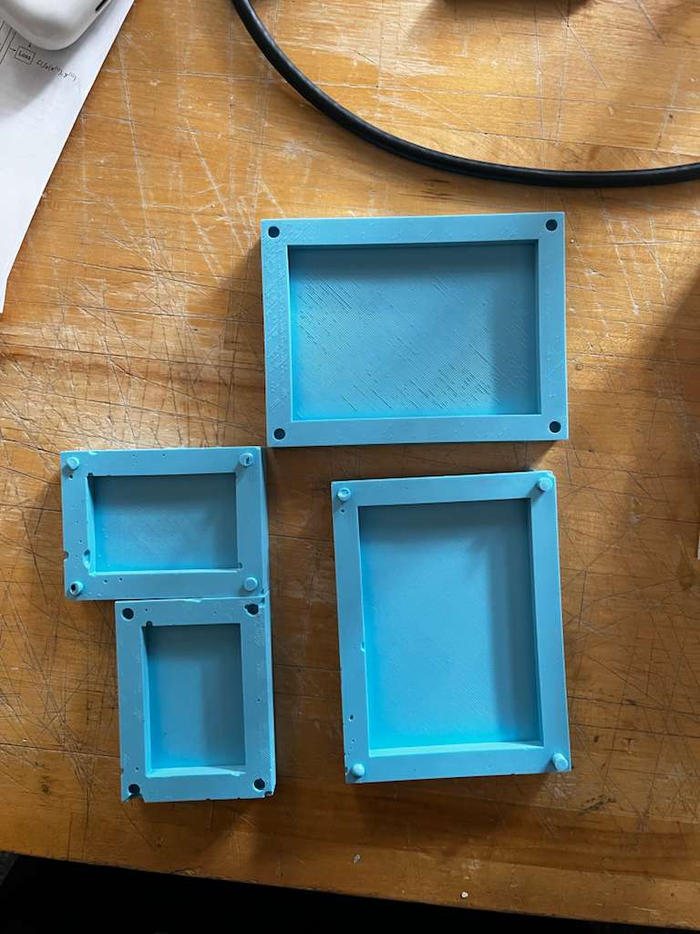
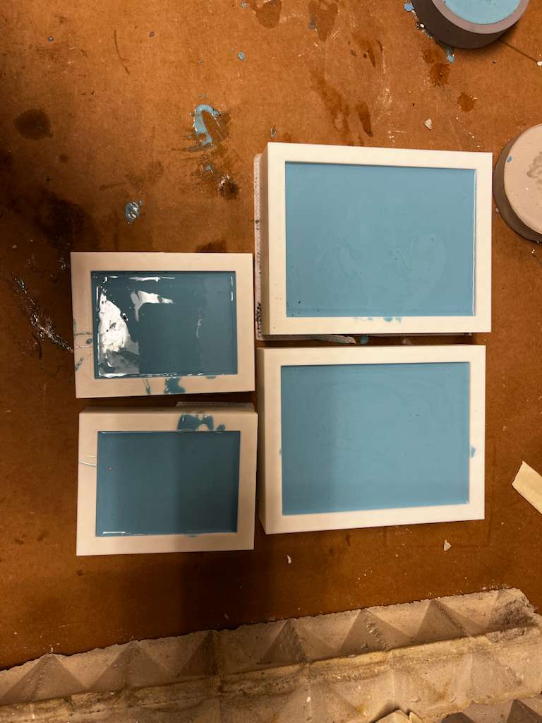
For the resin-casted token, I used leaves and molds I had modeled, 3D printed, and produced during Molding and Casting week. I purchased fumeless resin, combined the A and B chemicals, and added the NFC tags along with leaves collected from the site. After eliminating air bubbles and waiting 24 hours, the token was complete.
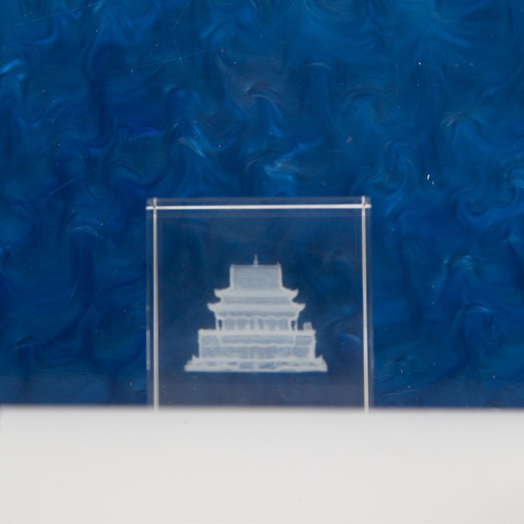
The glass-engraved token came from wildcard week. The photogrammetry model used for engraving is from one of the Gaussian splats included in this project, which we'll discuss later.
Gaussian Splat Scans
This project includes three Gaussian splat demos. All data was processed this semester, each with unique properties. The brochure I designed for the final presentation lists their details.
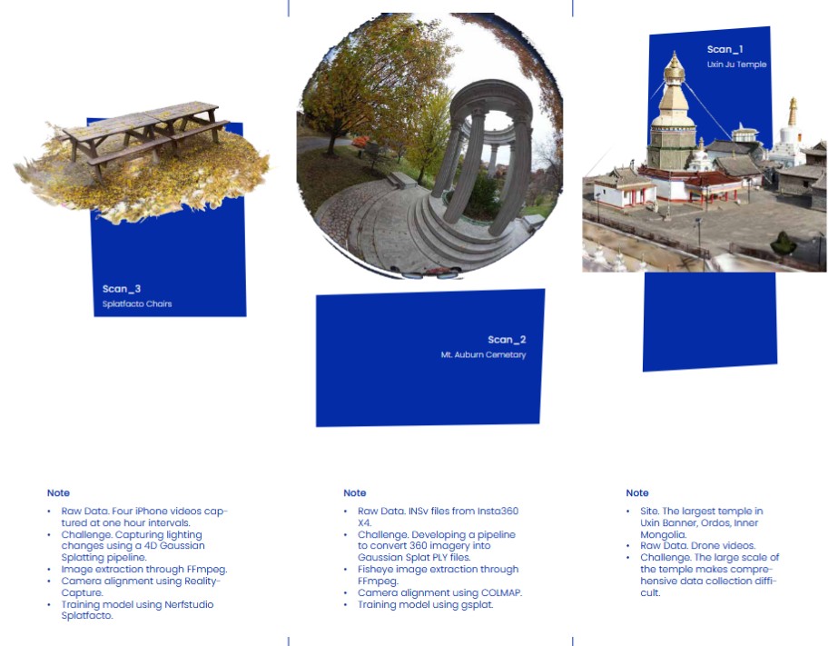
The first is Uxin Ju Temple, the largest temple in Ordos, Inner Mongolia. The raw data came from drone videos I collected for another project about two years ago. The site is massive, requiring many photos to generate a comprehensive scan. The main challenge for this scan was its scale. For this one, I used a ready-made commercial Gaussian splat generation tool called Luma AI.
The second scan used 360° image sequences from an Insta360 X4 camera. Scanning a space differs significantly from scanning an object—the key difference is camera direction. When scanning an object, cameras point inward, creating highly overlapping images that simplify camera alignment and sparse point cloud generation. When scanning a space, however, coverage becomes the main challenge. We tested 360° cameras to achieve better overlap between images. This is still an ongoing process and hasn't been entirely satisfactory yet.
For the second and third scans, I used two open-source repositories: Nerfstudio and Gsplat.
For the third scan, we wanted to capture time within the scan—also called 4D Gaussian splatting. I captured footage of the same chair every hour from 2pm to 6pm to animate the Gaussian splat. It was successful and can be seen in the gaming engine viewer, but I wasn't able to make it work for browser navigation, so the animation isn't visible in this project.
Case Design
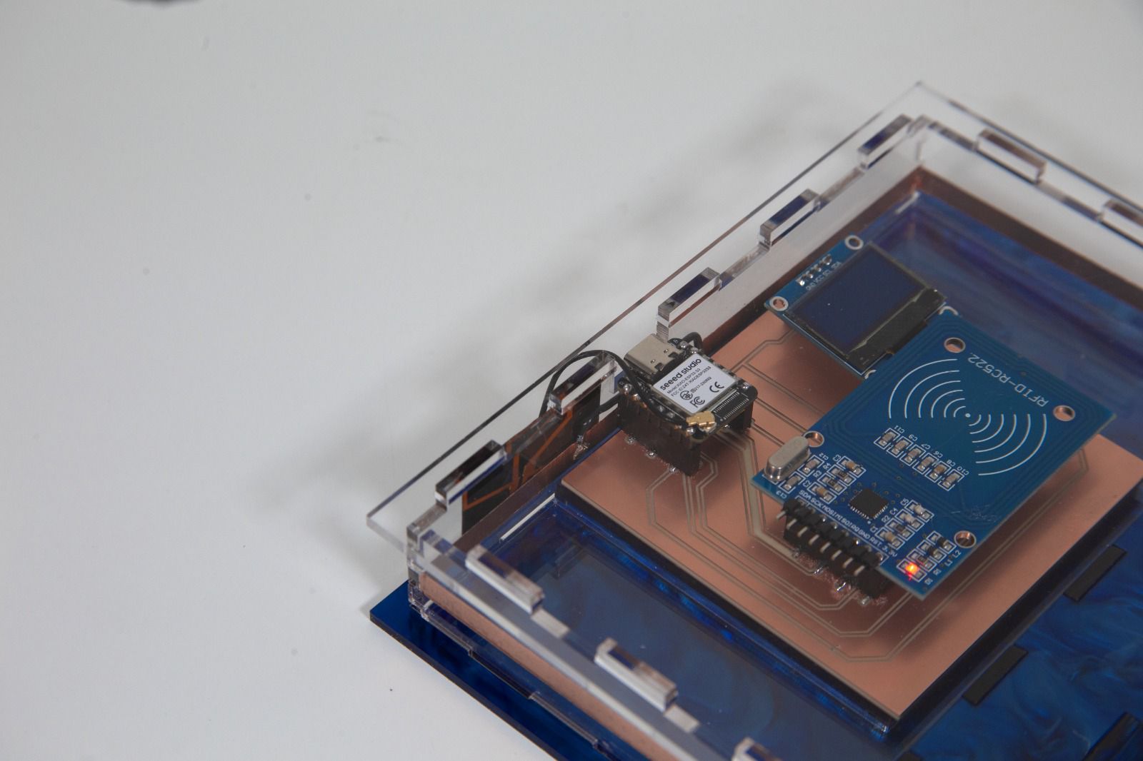
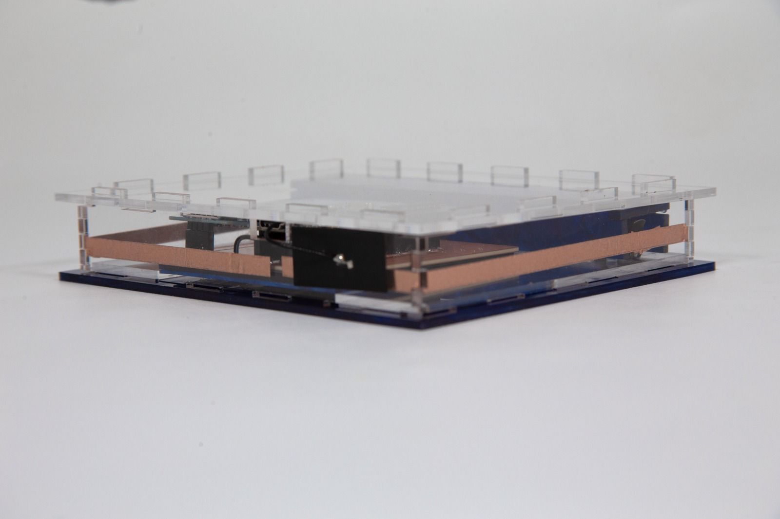
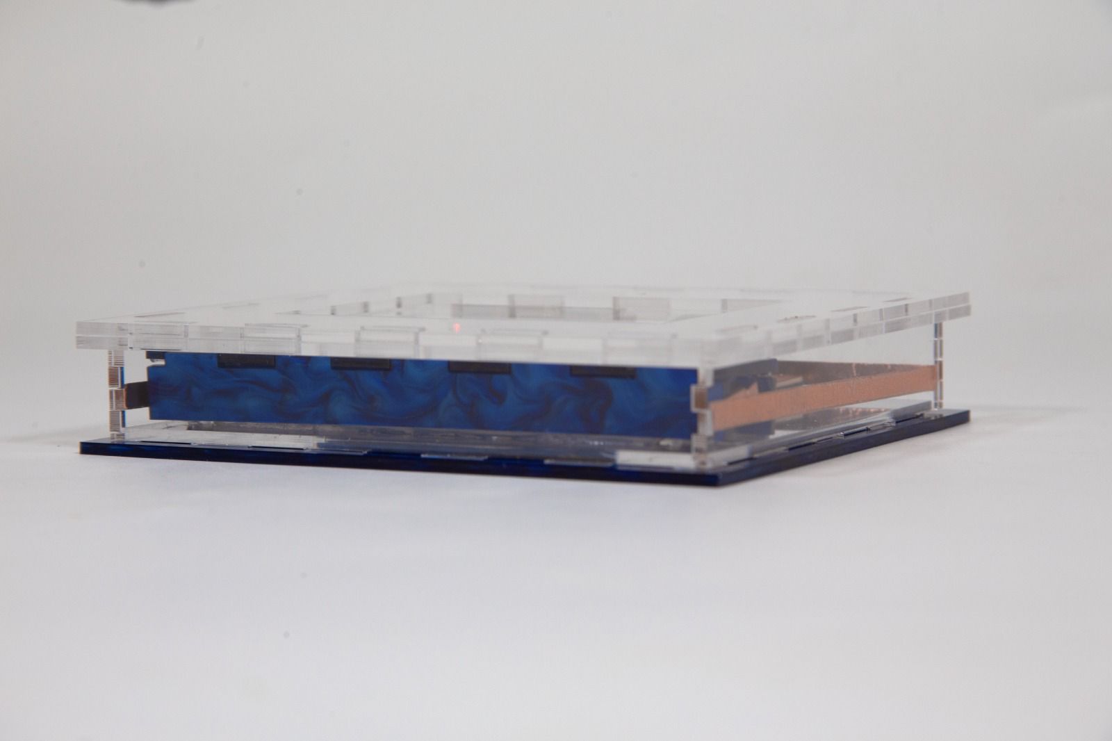
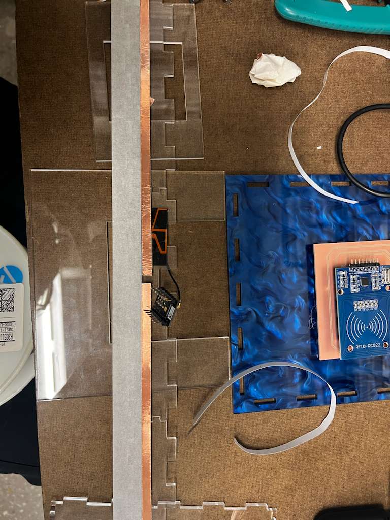
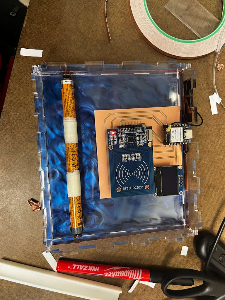
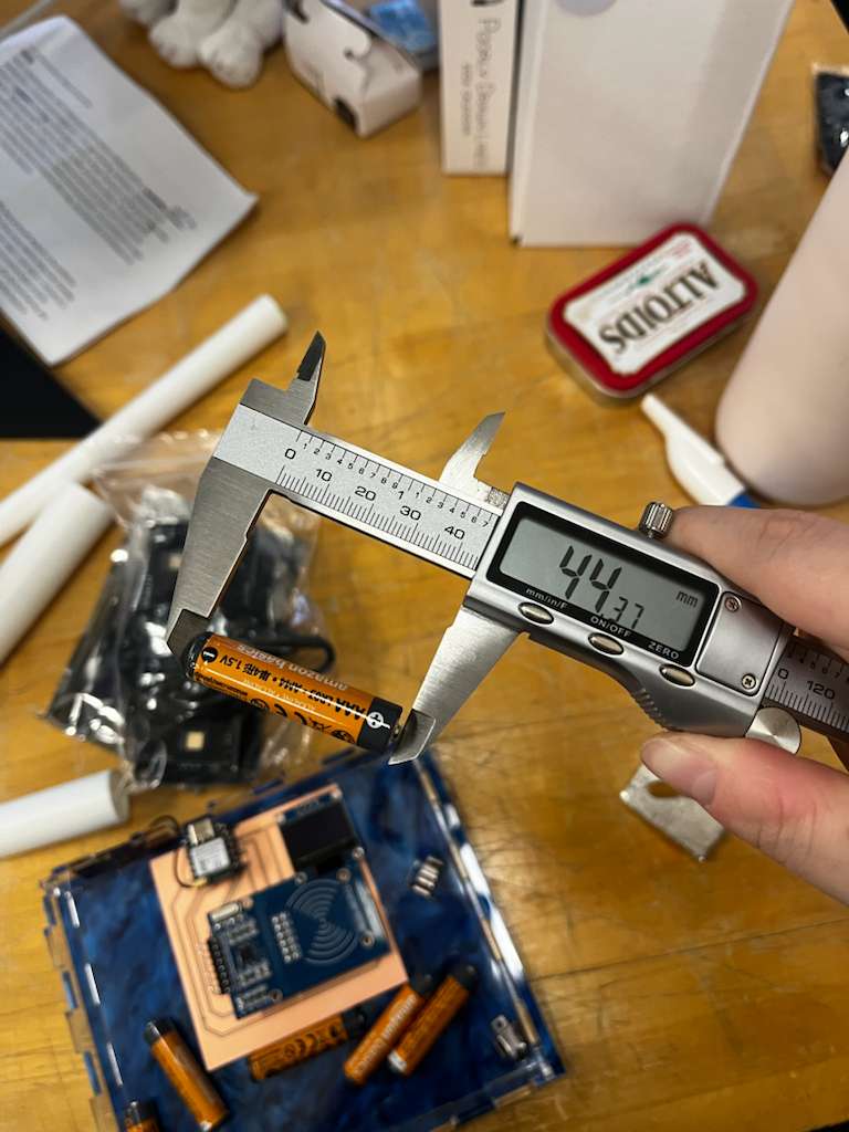
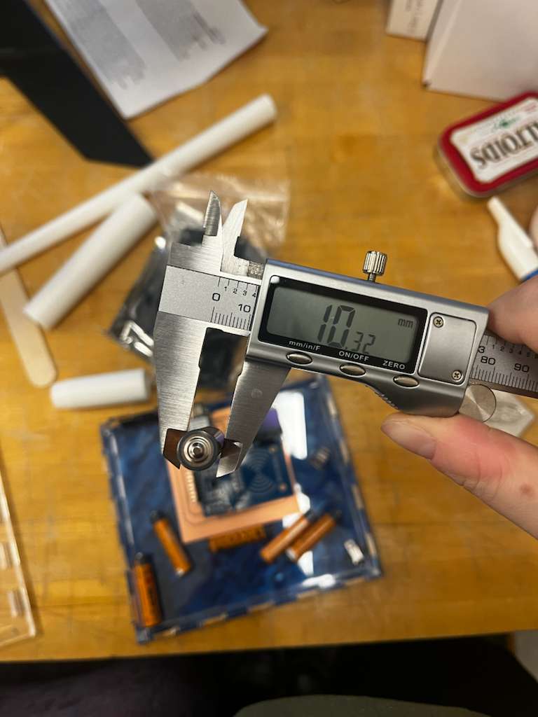
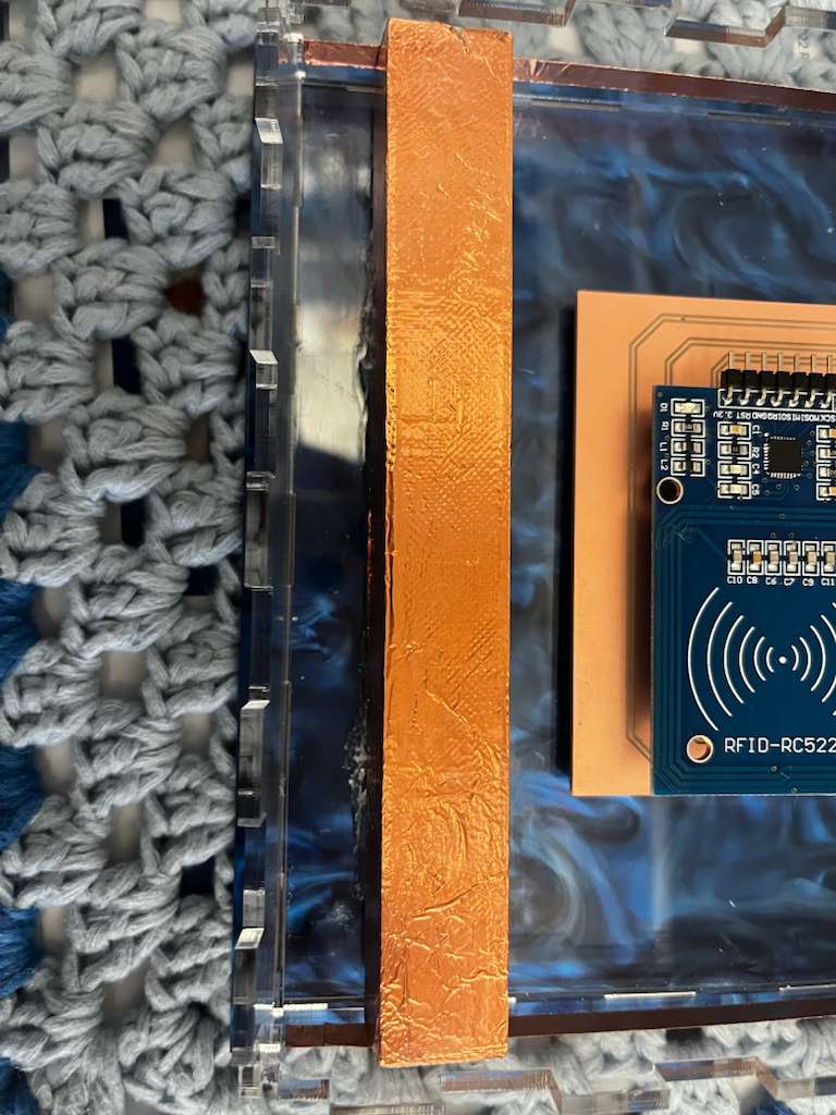
Although people might think case design should be the easiest part of the project, it was actually the most time-consuming and complicated process. There were four main challenges: allocating the thickness and location of each component to ensure the RFID reader could easily read the tag; making the system look wireless through a milled circuit board and copper tape; covering all the rough parts to make the case look polished without affecting functionality; and making the case modular for different-sized tokens with easy assembly and disassembly.
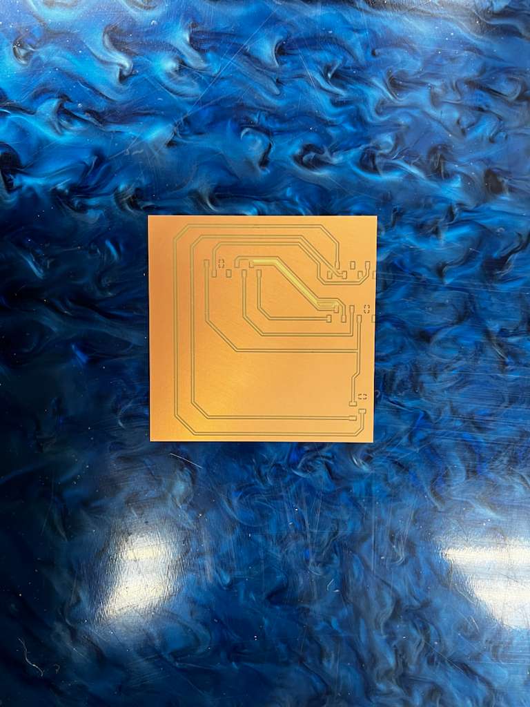
First, I milled the circuit board again and purchased a blue acrylic to give it a specific visual aesthetic.
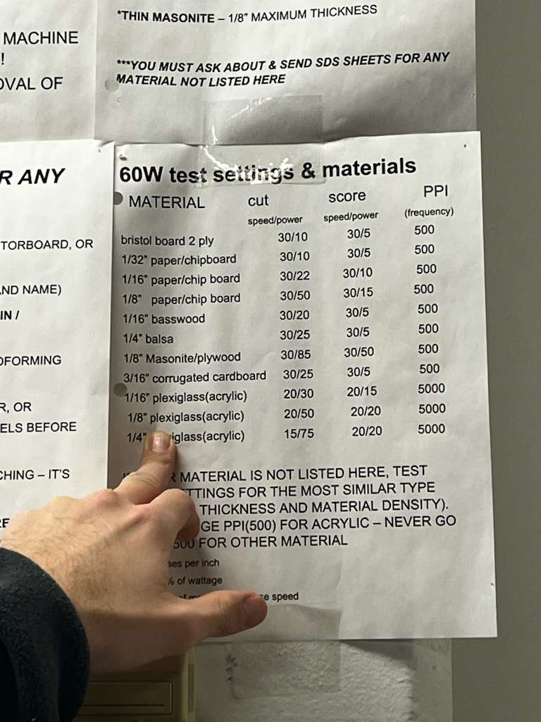
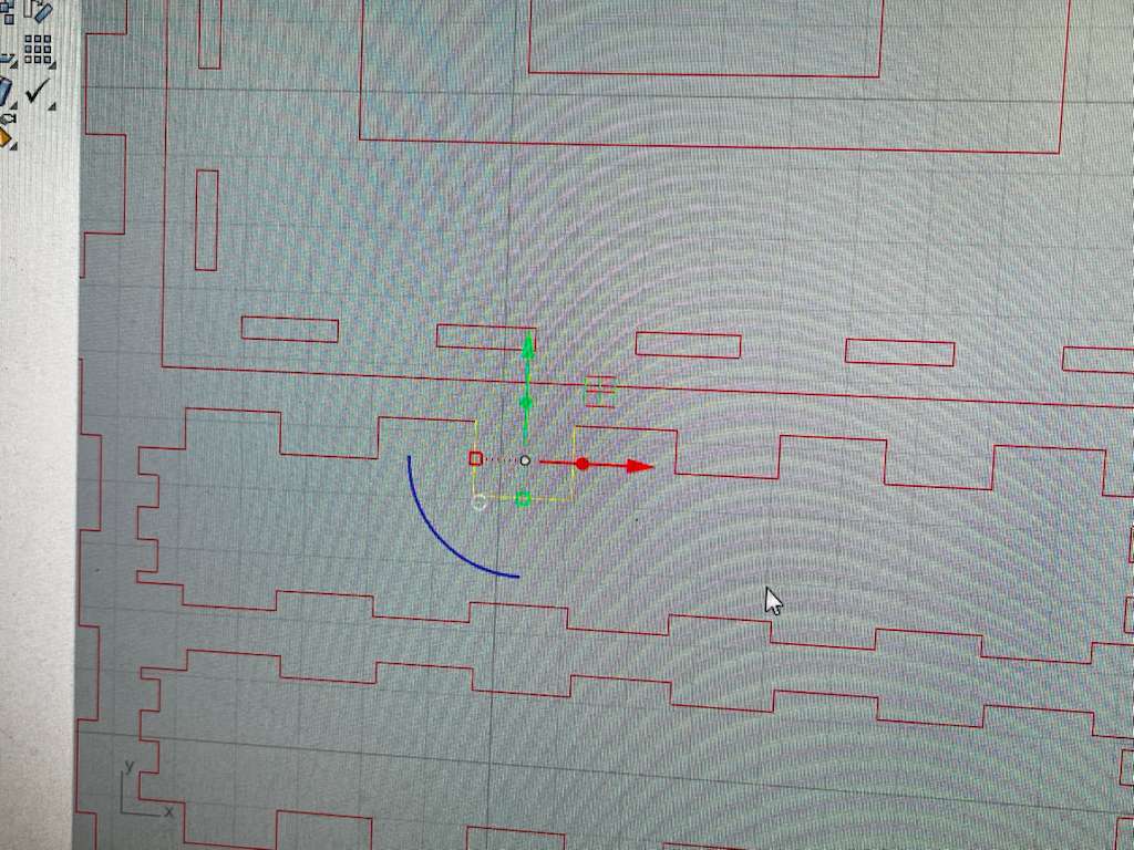
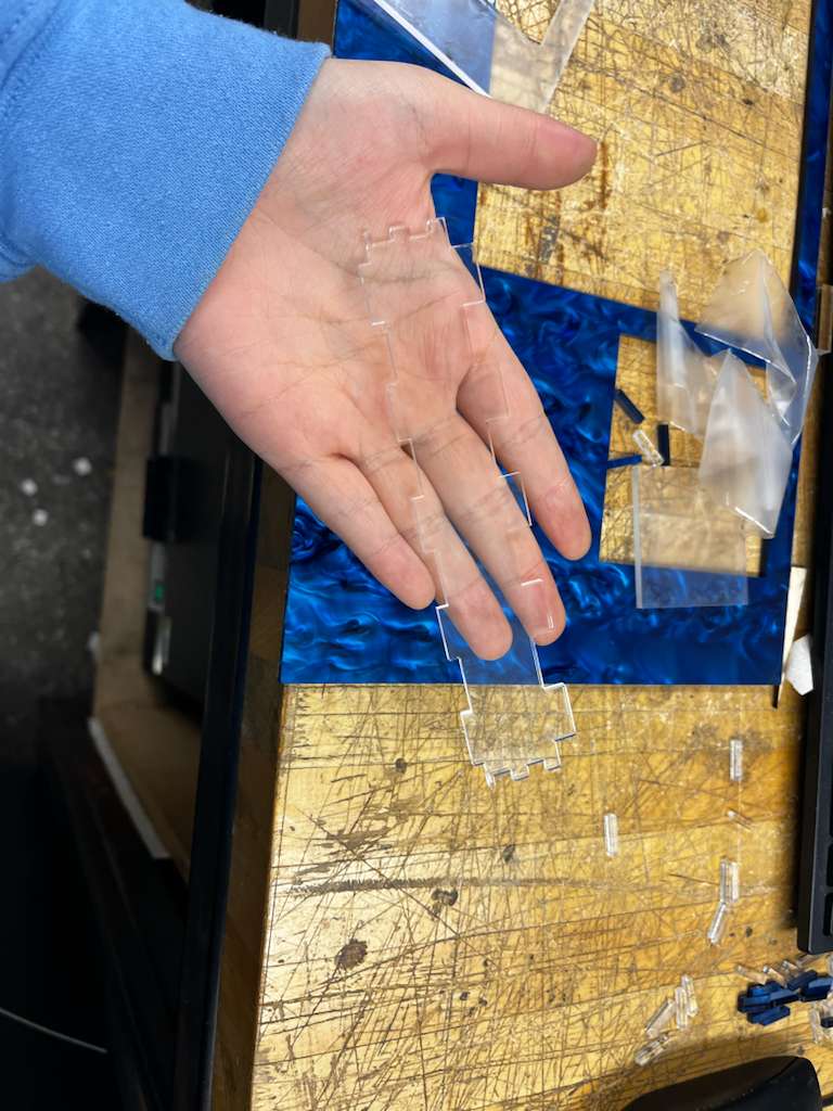
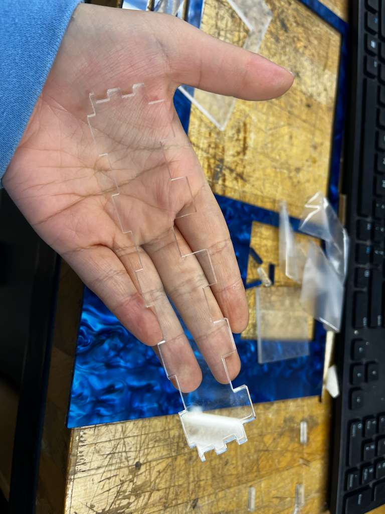
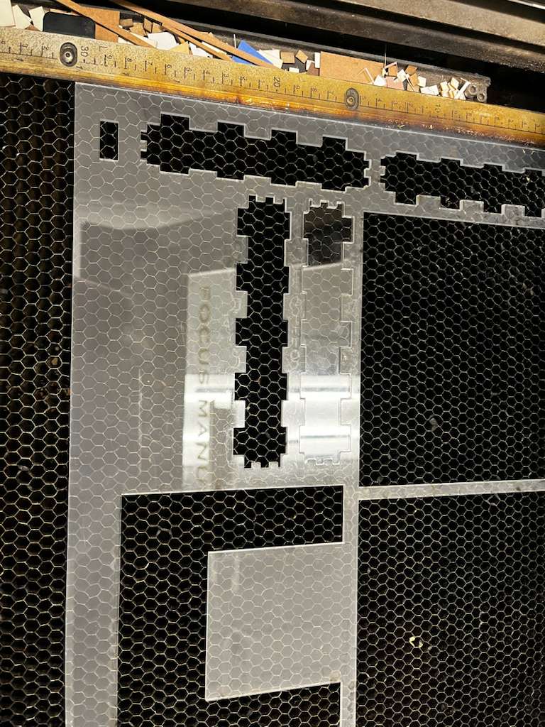
Then I've had the first iteration of box design and laser cut the file:
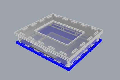
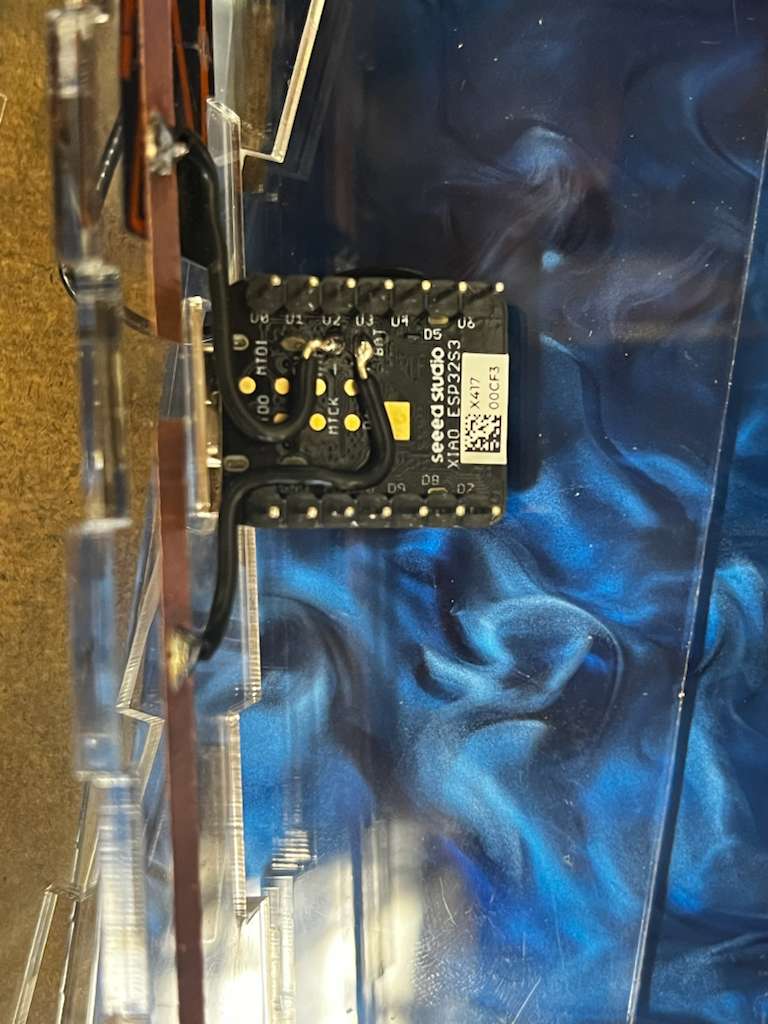
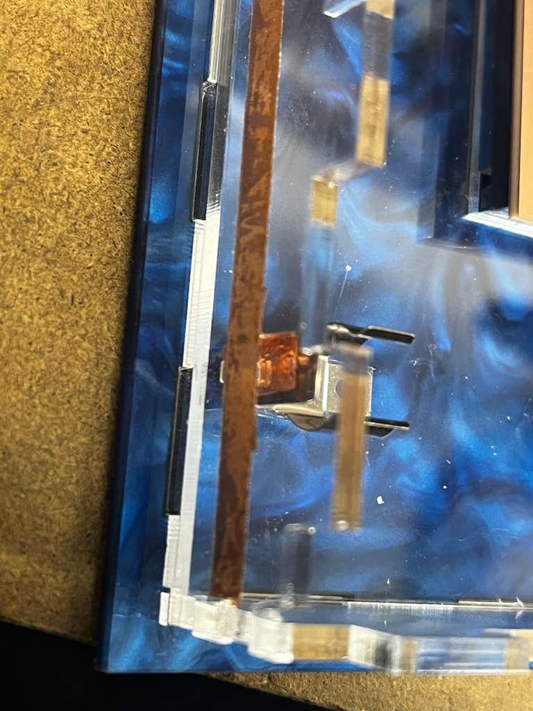
The first challenge was exposing the XIAO microcontroller's port. Since I designed all connections as finger joints, the solution was straightforward: lower one joint to create a void for the microcontroller. I also positioned the board to align with the XIAO's exact location.

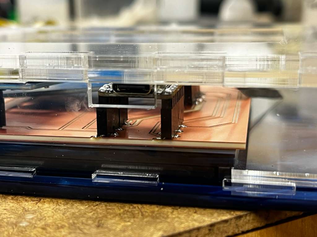
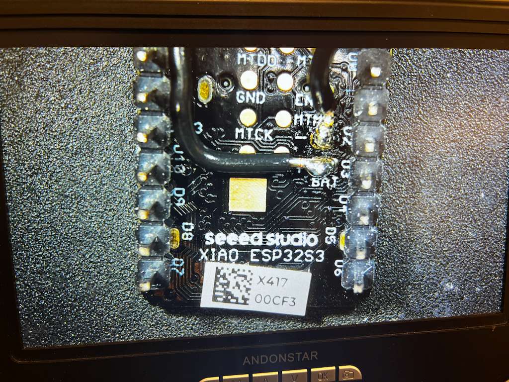
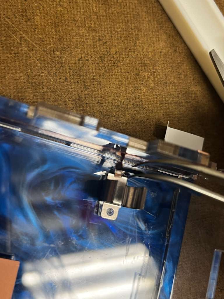
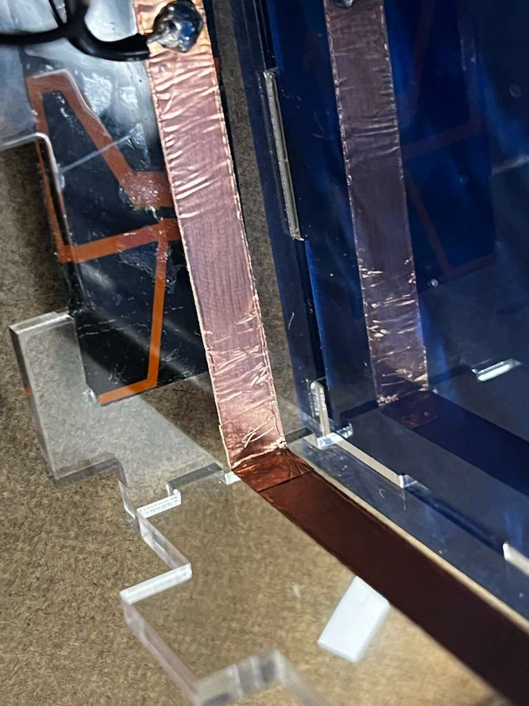
Because I also wanted to make the project stand alone, based on Anthony's advice I used three AAA batteries as the power supply. I soldered the connections to copper tape that wraps across the inside of the box to create a cleaner look. Soldering to copper tape was definitely very challenging, but with the acrylic board behind it acting as support, the process became much easier.
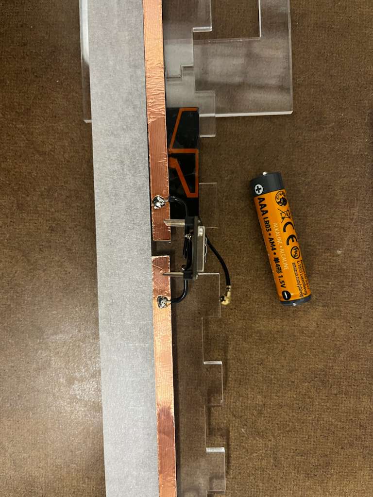
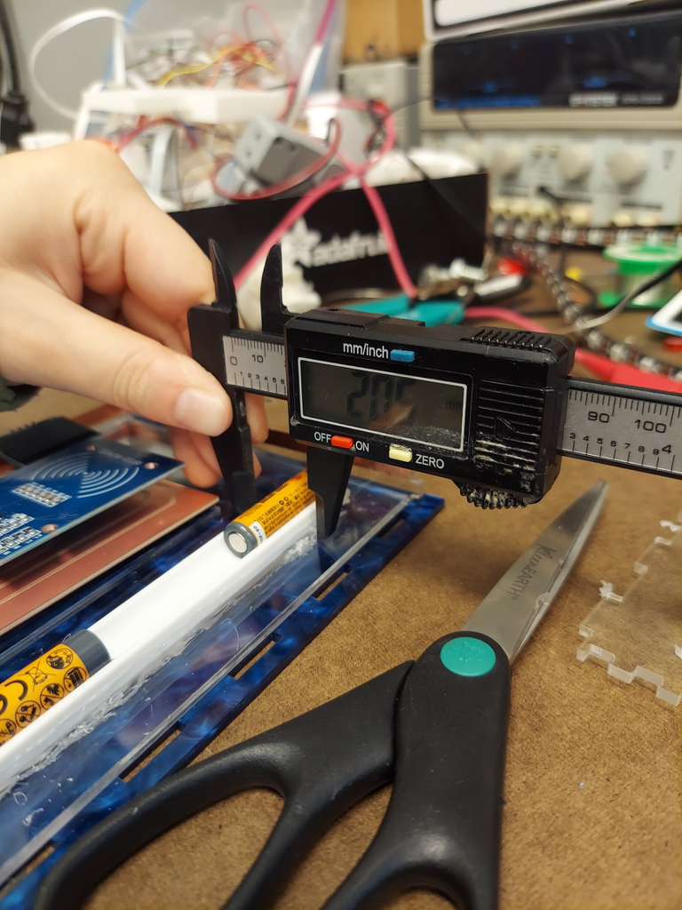
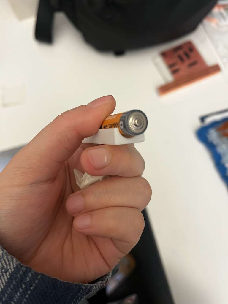
The location of the battery needed a lot of care and design, I had to go through couple of iteration of the battery box size, material selection, and design to get to the final clean look shown below.
Arduino Code
After the prototype, and also the fabrication and the design of the case which includes clear acrylic, copper board and tape, and the Lapiz Lazuli blue acrylic sheet as the base sheet, i wanted my web interface to also follow the color scheme and aesthetic, so final Arduino code is as following:
(Click to read code)
#include <WiFi.h>