Week 6 — Electronics Production
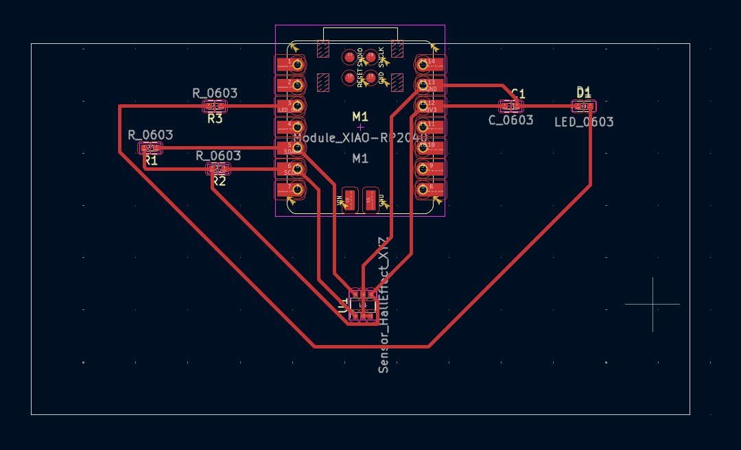
So, as a recap, from last week, I was able to export the black and white png for my board. If we wanna see the design, click here. In short, what I wanted to do was to have my board to have the LED light on whenever there’s a magnet getting close to the hall sensor.
And last Friday, I joined the group training held by Jen for the board cutting.
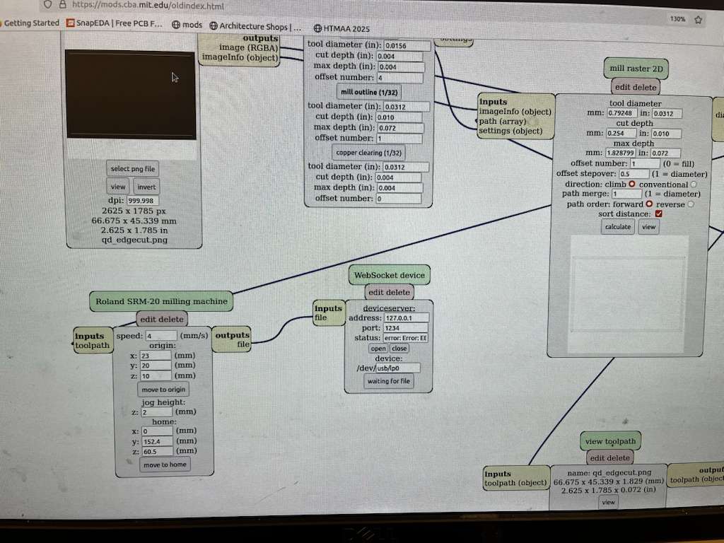
SRM‑20 milling setup
I started with the SRM‑20 machine, 1/64" bit for tracing and 1/32" mill for cutting.
There were some terminal issues, and Gert kindly helped us with that.
To solve the terminal issue, all we had to do was go to the js folder,
right‑click to open the terminal and type:
node deviceserver.js ::ffff:127.0.0.1 1234and voilà, the problem was solved, and I could cut my board. Following are video footage of the timelapse
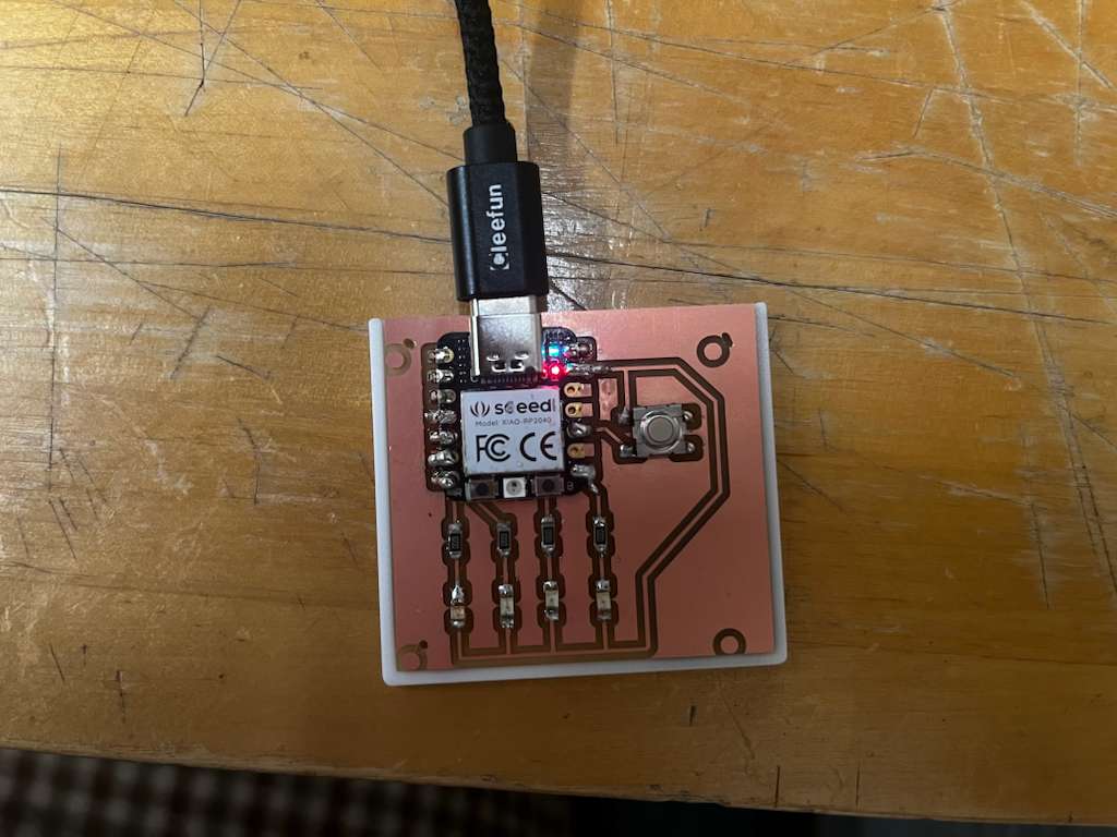
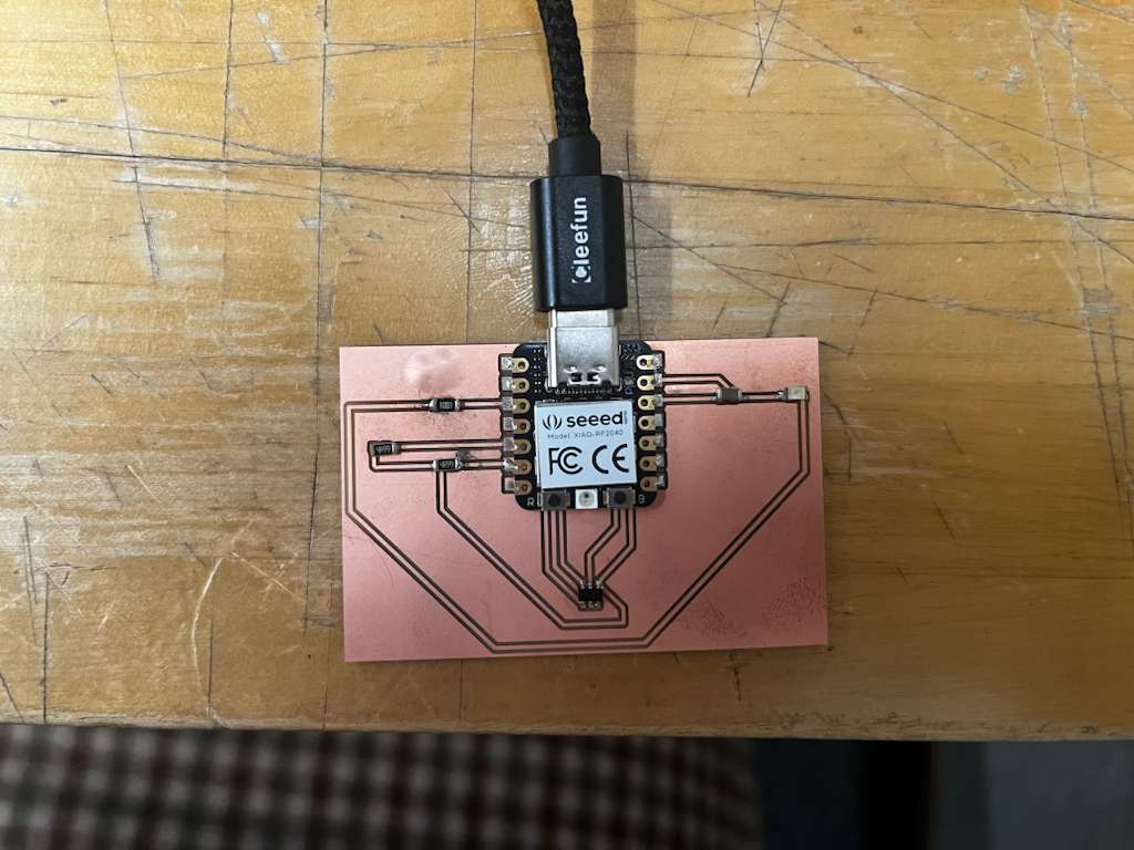
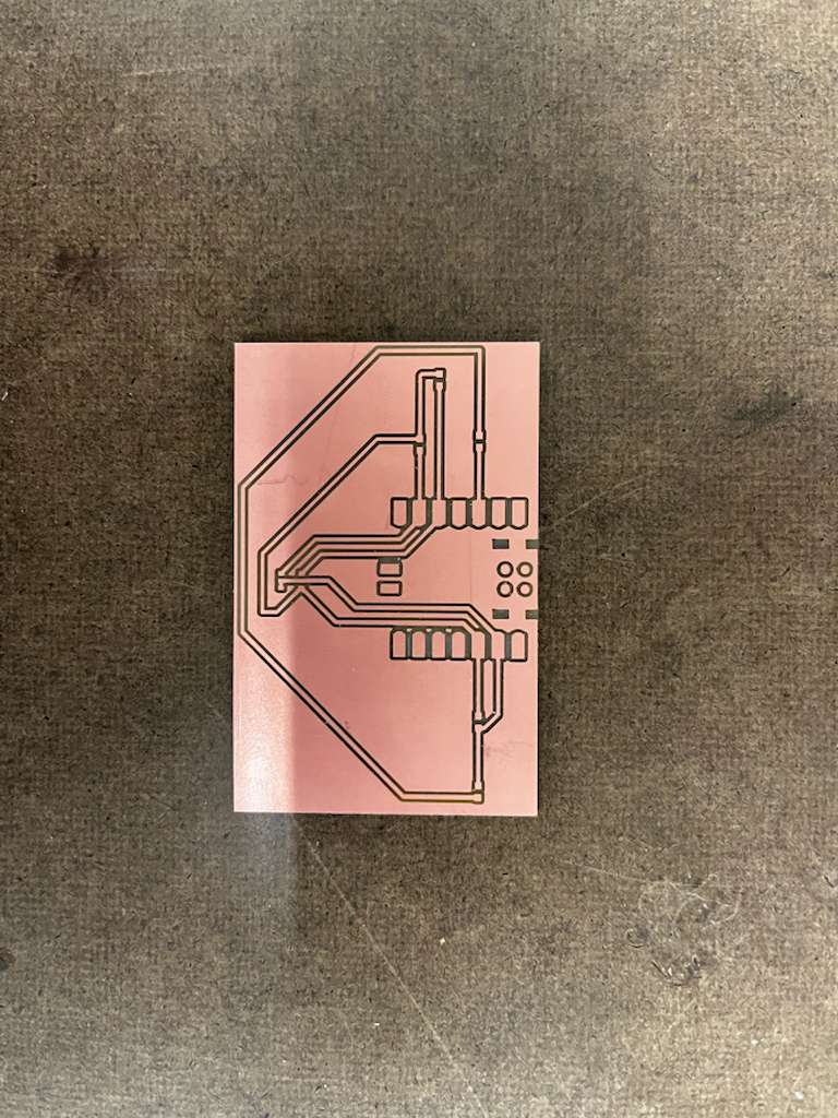
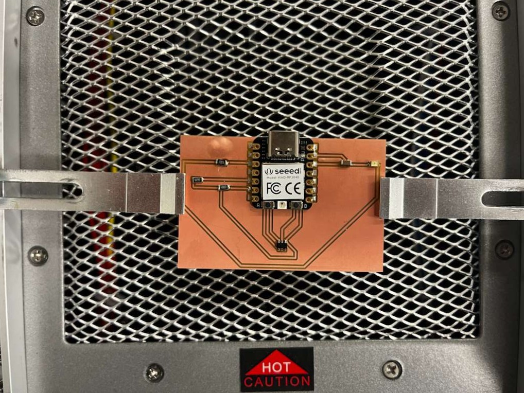
Below is the image of the finished board, and next to it is the comparison of the original board design png
Soldering reality check
So far, everything was working okay until I started soldering and i realized, i am really not skilled at it, and prototyping within an hour was impossible because of my shaky soldering skill.
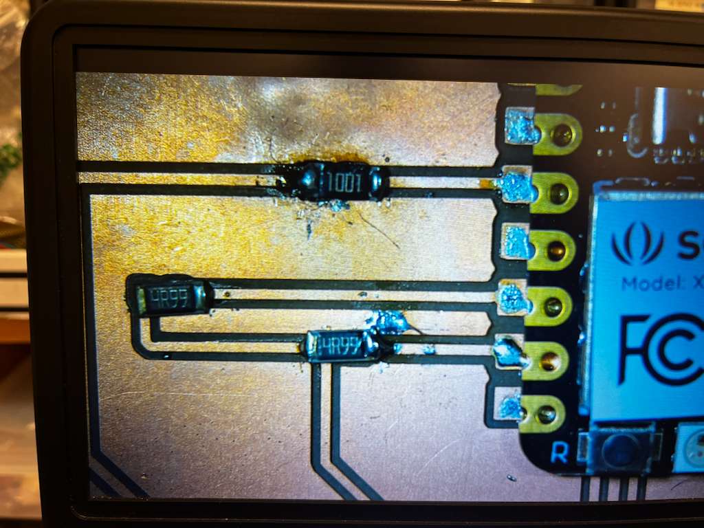
I tried soldering with wire first, but I didn’t really think it through, and I used the solder wire with 0.6 mm diameter instead of the one with 0.5 mm, so it got really messy. Below are the board under microscope, I know i messed up, i’m sorry, i’ll go to office hours and get help, please don’t yell at me TAT
Since the wire really gave me a hard time (which I’ll practice more on), I started trying the hot air for solder paste, especially for the sensor that has small pins, and I also did the same for the XIAO.
Arduino setup for XIAO RP2040
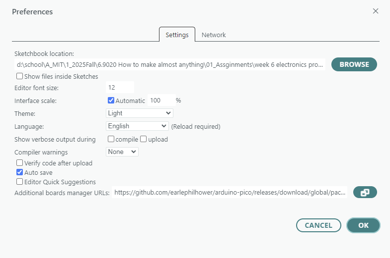
Now it’s time to go to arduino and see if this actually works. first and foremost, here’s the link of the document of xiao from seeed studio that i referred to— in File → Preferences paste the board manager link.
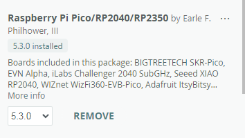
Then install board manager “Raspberry Pi Pico/RP2040”.
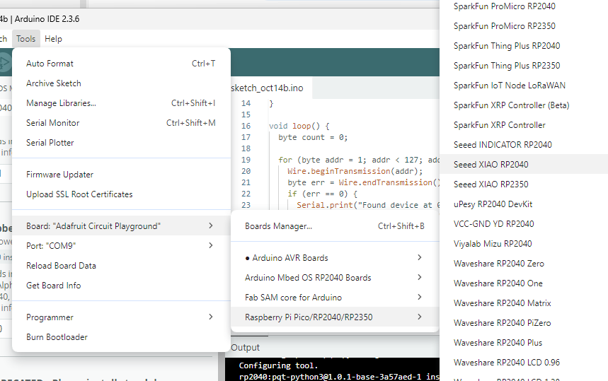
Now I can finally select the correct board.
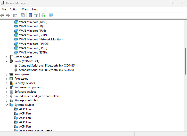
but i couldn’t find the port, there is something wrong with my xiao, I think I blew it with hot air too much and i broke my xiao. To test it, I used my friend Anita’s xiao and my xiao — my computer was able to detect her xiao, the led were on and the example code got uploaded, while mine didn’t even show up in device manager.