Code meets silicon. Microcontrollers and real-time systems explained.
[ MISSION OBJECTIVE ]
Dive into the world of microcontrollers and embedded systems. Understand datasheets, write code that interacts with hardware, and bring digital logic to the physical world.
[ DATASHEET EXPLORATION ]
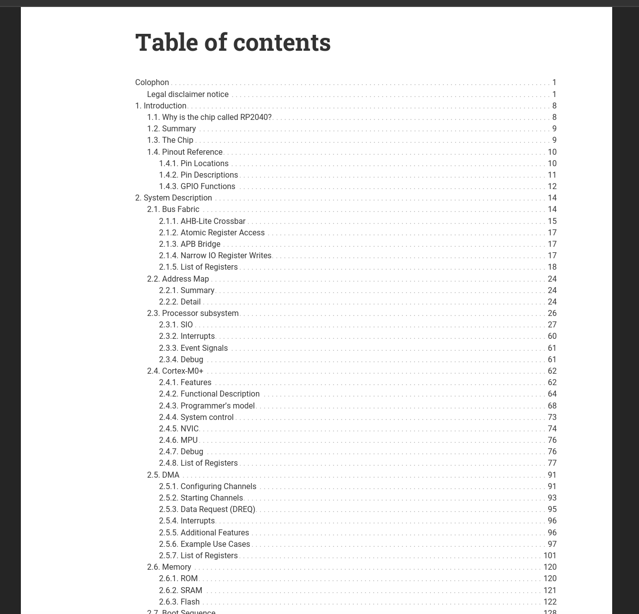
Assignment: Browse the data sheet for a microcontroller.
Figure 1. The data sheet for the RP2040, if printed, would be 70 times thicker than the processor itself.
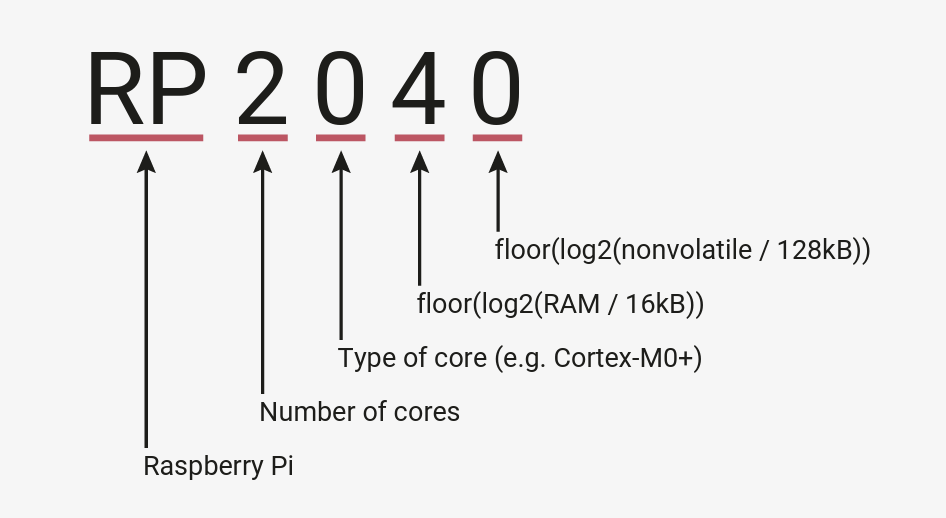
Figure 2. I appreciated the etymology of the processor name and the general naming convention. Unsure of the significance of the last two digits. RAM size?
[ EMBEDDED PROGRAMMING ]
Assignment: Write and test a program to interact and communicate using a microcontroller.
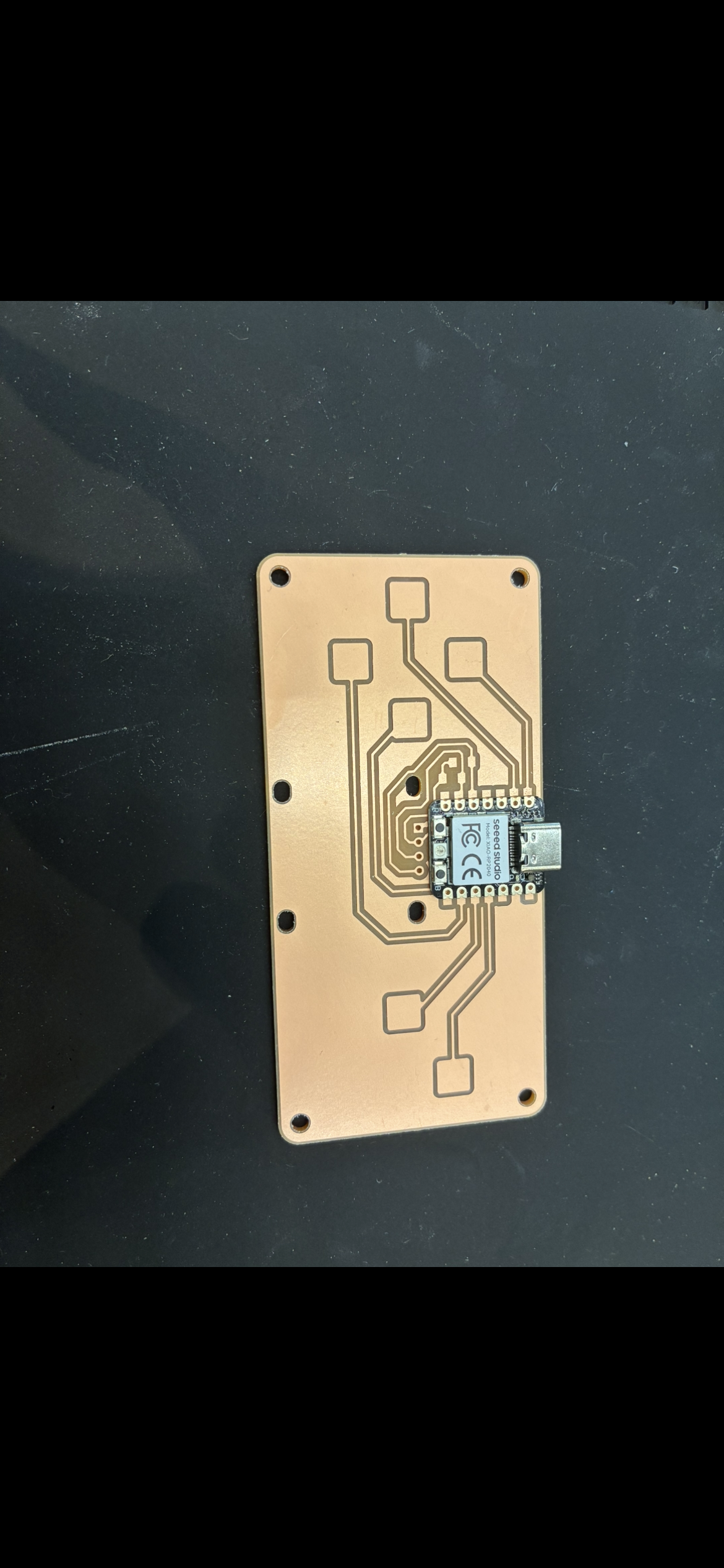
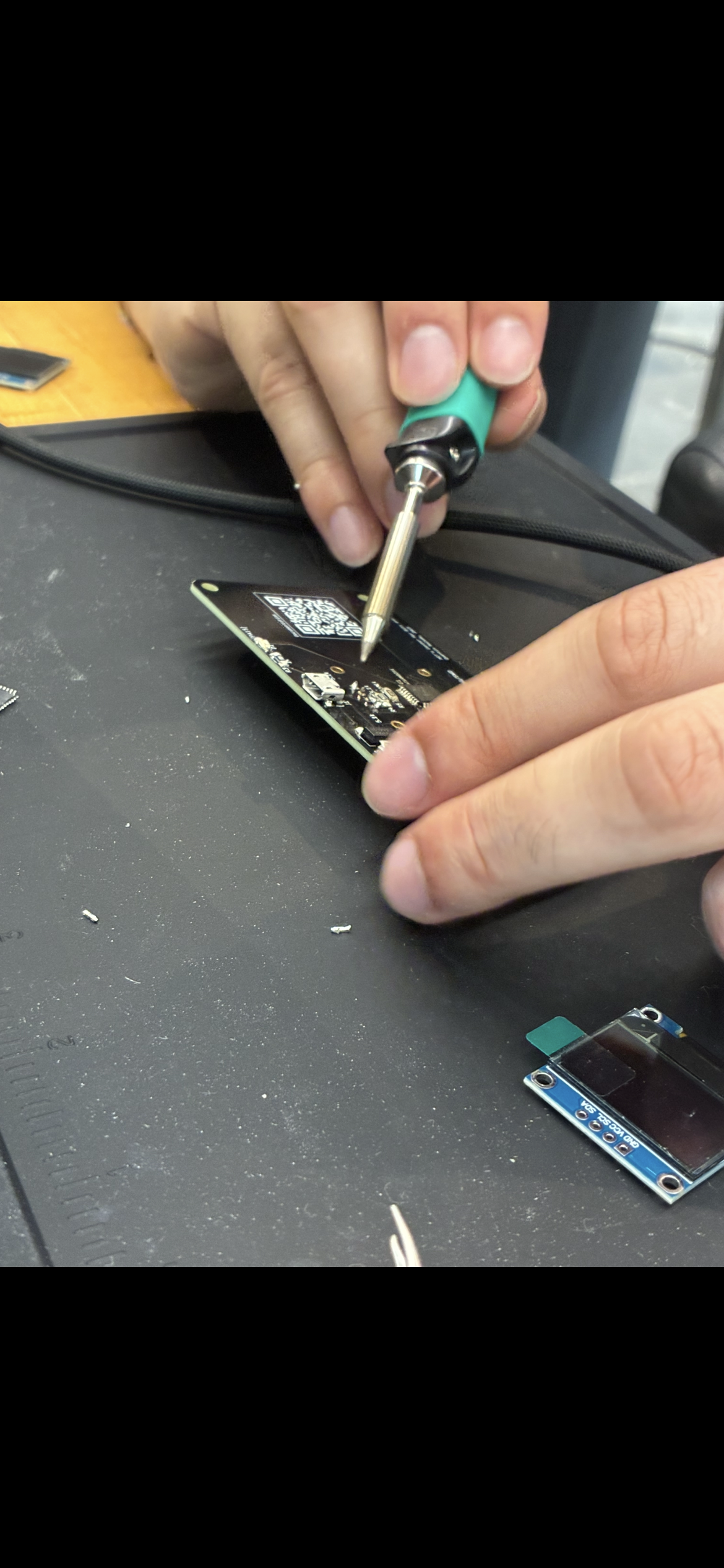
Figure 3. I soldered the board, but the screen catastrophically ripped out.
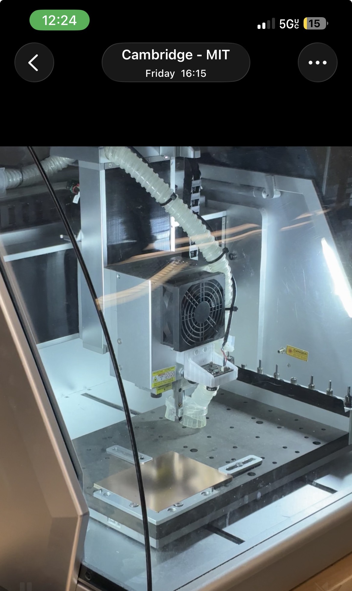
Figure 4. They milled me a new board, but broke the mill in the process. Just documenting my failures here.
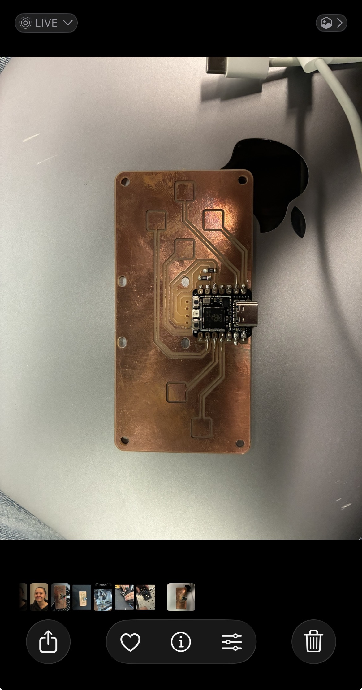
Figure 5. Quentin kindly helped me salvage another board which had power issues.
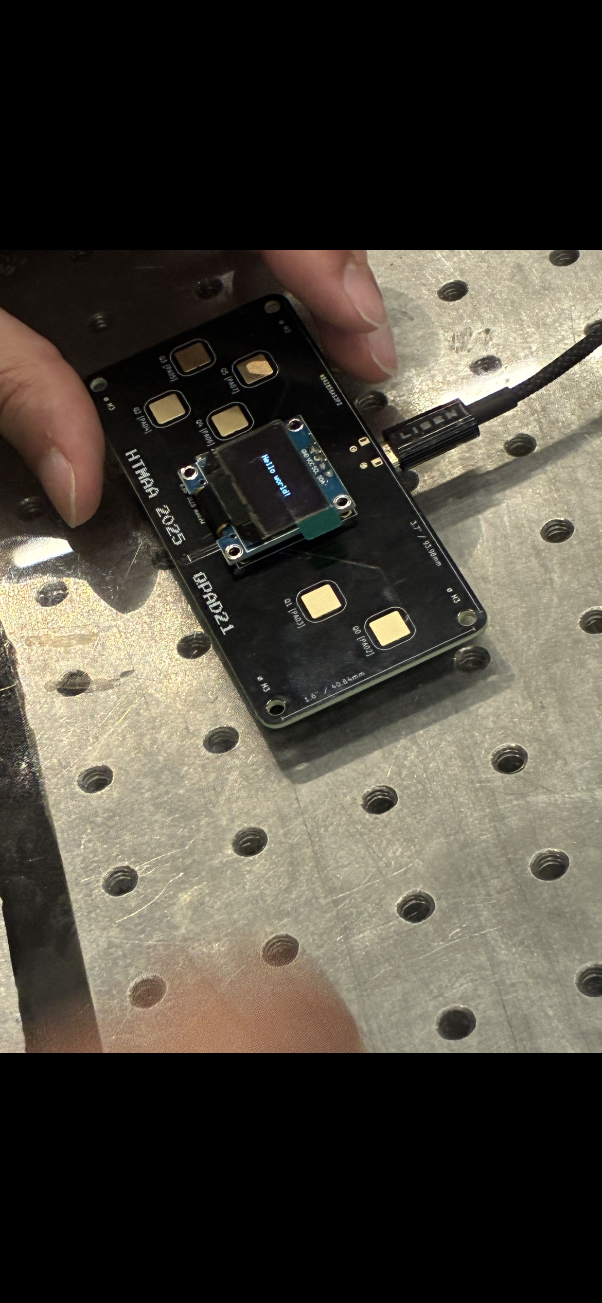
Figure 6. Success! After this I ended up trading the SAMD board for an RP2040 to try working on pico architecture.
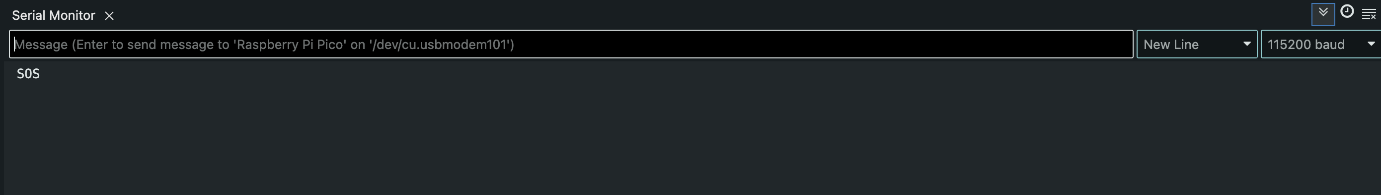
Figure 7. Due to the screen having ripped out certain connections in my board, I only had access to a few buttons. Limited by hardware, I made a morse code telegraph.
Figure 8. You can see the display leads ripped off the board. Some of the "buttons" were also damaged. I decided to adapt.