Week 7: Input Devices
Project Plan
This week I want to work toward a functioning version of the actuators that I will need for my final project. Neil pointed me to a super interesting
project by Jake Robert Read on Field Oriented Control where he tries
to develop a closeod loop control system for a generic stepper motor and turn it into a high precision servo motor. This would be awesome for my final
project, as it would be super useful with respect to the controls side. It would also be a great learning experience and certainly push myself. After
reading the work for the first time, I determiend that it was quite far out of my skill range but I am still tempted to see what I can actually begin
doing.
This week, I want to build a PCB to control a stepper motor using two HBridges and do some basic current sensing do get feedback from the stepper motors.
Once I'm able to get some basic readings, I can make a plan to move forward but I want to try and do this in small bite size steps. I also plan on meeting
with Anthony to discuss a plan for how to approach this logically and make steady progress. I would also like to maybe implement a magnetic encoder on the
end of a cycloidal drive that I want to design as part of the actuator for my final project. This encoder would close the loop of the stepper. I'm not entirely
sure if I actually want/need a closed loop stepper for my project or if I am naive and simply think that I do because it sounds cool. I do think that I am
drastically underestimating the undertaking that it would be though.
Exploration
I've spent a good chunk of my time this week so far just reading a bunch of different write ups on projects exploring field oriented control of stepper motors as well as about the development of a cycloidal drive. Here are some of the articles that I have looked at:
- Jake Read's article on FOC
- Sam Calish's work on a closed loop stepper over IAP
- Design of a cyloidal drive
Execution
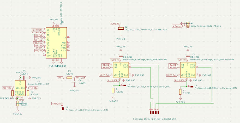
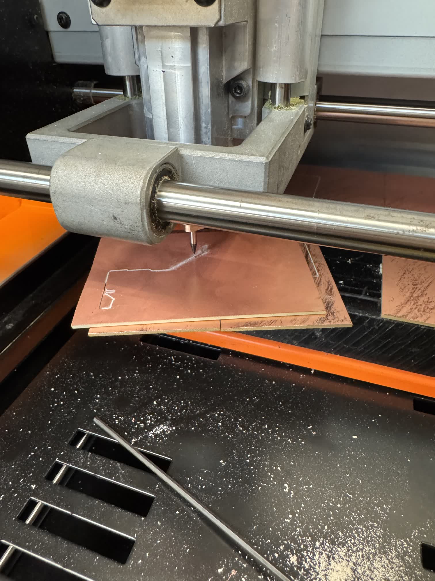
Before I could do any current sensing, I had to design the PCB to actually controll the stepper motor. After my experience in week 5, I immediatley went to the
class website to see what examples I could find for how to work with the DRV8251a drvier, the HBridge that Neil recommended. Fortunatley I found a schematic and
PCB that Neil had designed that I was able to roughly follow, I also read through the
data sheet to make sure that I wasn't going to mess anything up and if there were any important details taht I was missing. I also wanted a better understanding
of the component that I was using.
What makes the DRV8251a special, is that one of its pins, IPROPI, outputs a current proportinal to that through the motor, this is how people are able to do current
sensing through this component. Here are some excerpts from the data sheet that explain the system by which the controller does the sensing.
After I dsinged this PCB, I was in the architecture shops and was talking to Gert about my project and plan. We began talking about how I might do positioning for the
stepper motor and I brought up magnetic encoders. The class currently doesn't stock them but I figured I would try the next closest sensor and use a hall effect sensor,
and see what kind of results I could get with it. Thus, I jumped back into KiCad and added a TLE493D 3D hall effect sensor to my schematic and board.
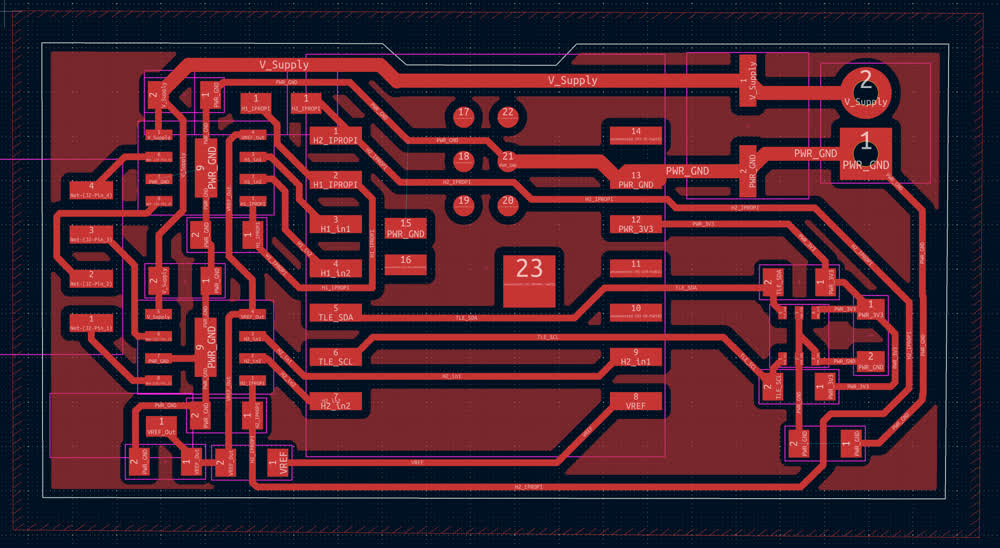
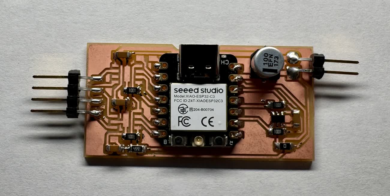
With the PCB machined and all the parts soldered on, here was most of the final board. The architecture shop didn't have the DRV8251A that I was hoping to use, they were supposed to have more coming
in later this week and so the board does not have the drivers on it.
Meeting with Anthony
During my meeting with Anthony we talked through most of my project plan. The overarching topic was refining the goals and choosing the manageable, fun, and core parts of my project to work on, not neccesarily the super niche, cool but not neccesary aspects of the project like designing a field oriented control system for a stepper motor. Quick side note: I didn't realize this was work that he was doing for his PHD in controls... With that being said, I decided that I didn't need the additional benefits of driving the stepper motor with the DRV8251A's and so I plan on just returning to the DRV8428 driver that I was working with a few weeks ago. We also discussed potential position detection systems for the steppers and linear actuator for my final project. I did a little bit of research after our conversation and decided to order a few AS5600 breakout boards to see if I can use them for the rotational actuators. I also wanted to experiment with the VL53L1X for ranging as it might be useful for the linear actuator.
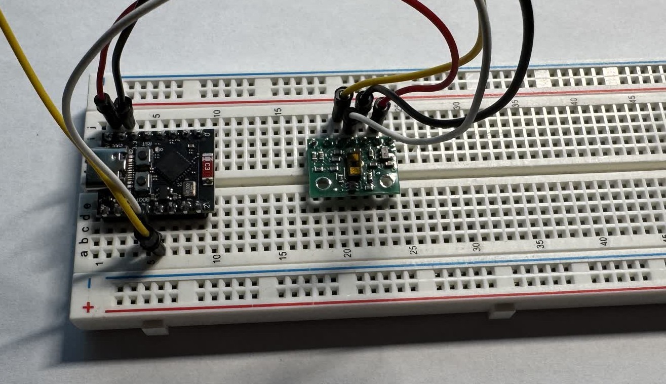
Using Sensors
Up to this point in the week, I haven't actually used any of the sensors like we were supposed to. I was originally planning on my sensor data being the current mirror in the DRV8251A but now I'm no longer using those.
I did have a board with a hall effect sensor on it but I didn't really see a use for it in my final project after I found the AS5600 breakout boards. The TLE493D simply doesn't offer enough resolution for the kind of
position detection that I want for my stepper. Needing something though, I decided to see if I could get it working and detect a magnet. I started by trying to use Neil's code on the class website which didn't work. It
was a combination of flashing code to the esp32C3 which would write the data to serial and then Python which would read and print the data from the serial into a visualizer.
Simply trying to get the sensor to read data without really an idea of what went wrong with Neil's program, I turned to ChatGPT. We eventually got it working after a few iterations and got the sensor outputting its
raw measurements as well as the magnetic field values. The code for this can be found at the bottom of this page. I then added a little bit of code to simply print when a magnet was moved within range of the sensor
and then when it was removed. Below are videos demonstrating these.
While testing and in the video you can see that when the magnet gets to clost to the MCU, it fails and stops sending data which I though was interesting. A great example of why people say not to bring magnets near your
devices.
This has potential for homing the position of the actuators that I will design but if I am able to use the encoders then I am not sure that I will need it. This was the work that I did to use the TLE493D hall effect sensor.
Unsatisfied and a little disappointed that I didn't think I was going to use it in my final, I wanted to try working with the VL53L1X as well.
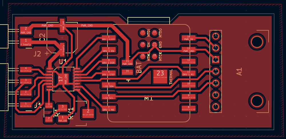
I designed another PCB, this time combining and ESP32C3, DRV8428, and a breakout board for the VL53L1X. The set up for the DRV8428 is a little different than what I did a few weeks ago. This is more based off of the model
PCB that can be found on the class website. I didn't end up milling it yet because I need to talk to Anthony about how to use the engraving bit, but also because
I want to stop quickfiring PCBs and maybe put a little bit more thought into them before I just keep spitting them out. I mean its great practice designing them, but I don't want to waste materials and components by
continually building boards. With that being said, here is the PCB that I designed for this.

Here is a video of the signals coming from the I2C data pin.
I'm not quite sure what exaclty I was seeing. In the code, during the loop, there are two calls to the sensor. One is to read it's status, I believe
as in whether or not it is able to get readings and the other is to get the actual range data. If I had to guess, I would assume that the shorter pulses
is the status data and the longer pulses encode the range data.
While testing the VL53L1X, I noticed that there is a fair bit of noise in the ranging. When held at a constant distance from something, ie. the floor
to the underside of a desk, there were a few mm oscilaltions in the ranges that it was returning. When using this in my project, I think I will use a moving
average of the data points to hopefully get a more accurate and smoother reading from the sensor.
Random Notes
- For a Xiao ESP32C3: SDA_Pin = 6, SCL_Pin = 7
- For ESP32C3 Super Mini: SDA_Pin = 8, SCL_Pin = 9
- For super mini, if you don't see anything on serial, make sure "USB CDC on boot" is enabled
Thoughts and Reflection
I am somewhat dissapointed with my progress this week. I had large aspirations which were quickly shut down and I feel as though I made little progress
towards my final project. There was still lots of learnign that took place though. I spent more time working in KiCad, gaining experience in PCB design.
I also spent more time reading through data sheets and feel as though I am starting to gain some small amount of familiarity with what they are talking about
in them.
While it was interesting to spend a bunch of time reading about the design of FOCs for stepper motors, I'm annoyed that I let it consume a good chunk of my time
available for the week, limiting what I was able to accomplish. I think I have a tendency to be overambitious and chase the complex, fascinating ideas, but I think
that it will be far more efficient to start small and expand. I know it is the spiral development that Neil mentioned and I was listening to him when he talked about it,
but I think I am starting to see its value on my own. I feel like I often find myself unable to achieve my larger goals because I got caught up on a niche detail. Where as
if I was willing to move past that cool, complex idea and do a simpler approach, I would have likely made more progress at the end of the day. I am going to try and focus
on this for next week and while moving forward with my final project. Working with breadboards and breakout boards while not great for final projects, are great for
rapid testing.