Week 8: Output Devices
Project Plan
This week's plan is to make basic, functioning versions of the actuators that I want to have as the base for my final project. I have a bunch of stepper motors and drivers at home so I am have all of the components that I need in order to get them working. I also have a fair amount of experience working with stepper motors as I have used them in previous projects so I am hopeful that I will be able to make some solid progress this week.
Execution
I started the week by working on setting up a simple system for the linear actuator. From a past project where I was disassembling a 3D printer, I have some spare
linear rails as well as a ball screw which happen to be exaclty what I needed for the system. The design was pretty simple, all I was trying to do was get a functioning
model of the system so I only needed three components. Two plates connecting the linear rods to one another and another that is the actuated bed. I then jumped into Fusion
360.
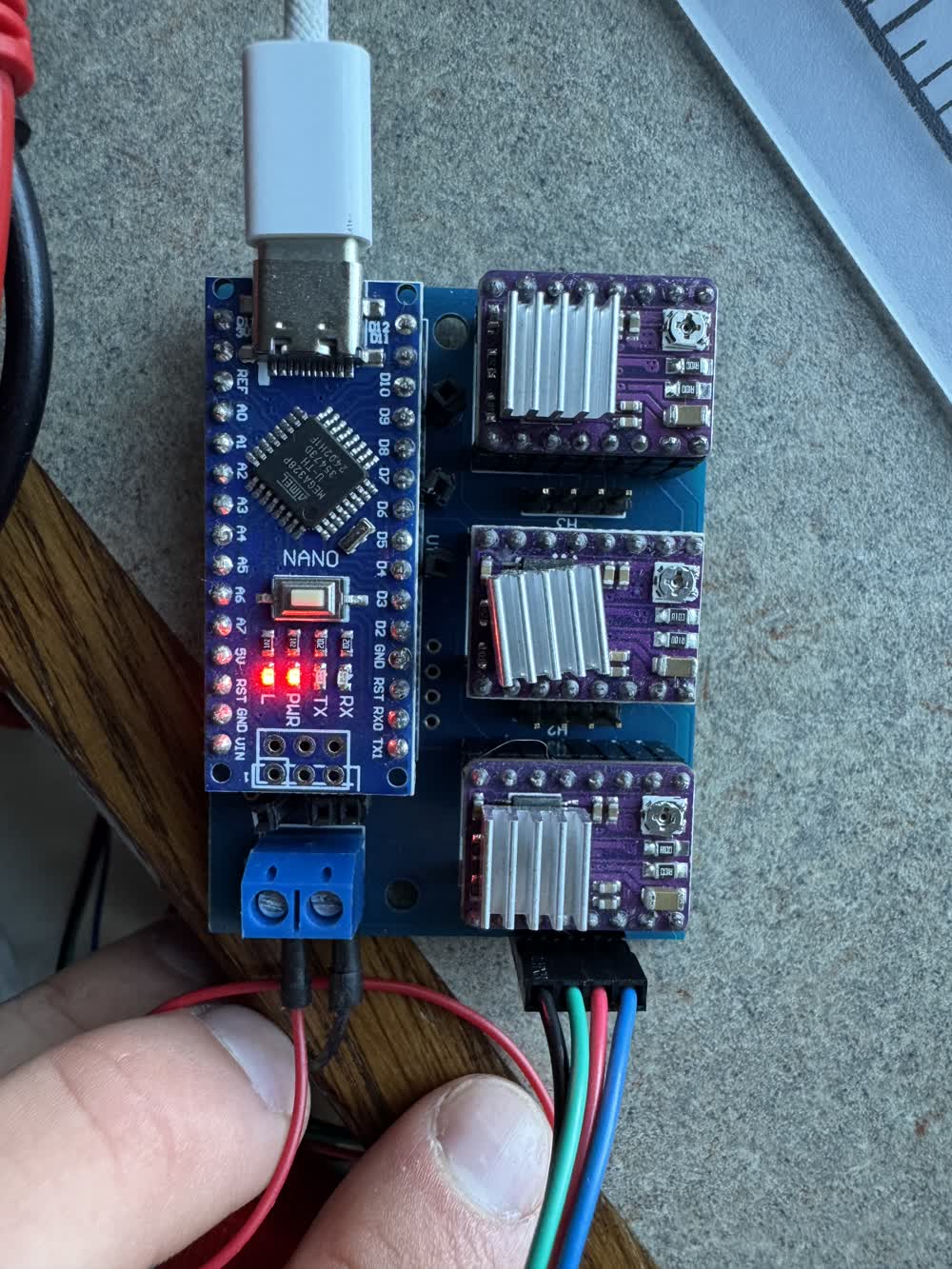
While these components were I wanted to go ahead and test the ball screw and stepper motor to just make sure that I could get it working. While looking through some of my porjects in my room,
I found this old PCB that I forgot I designed but it was perfect for this. It uses an arduino Nano and DRV8825 breakout boards with pinouts to easily run stepper motors. A simpler version of the
development board that I was trying to desing a few weeks ago.
With the simple stepper working, I was curious about the ball screw and hooked it up for another simple test.
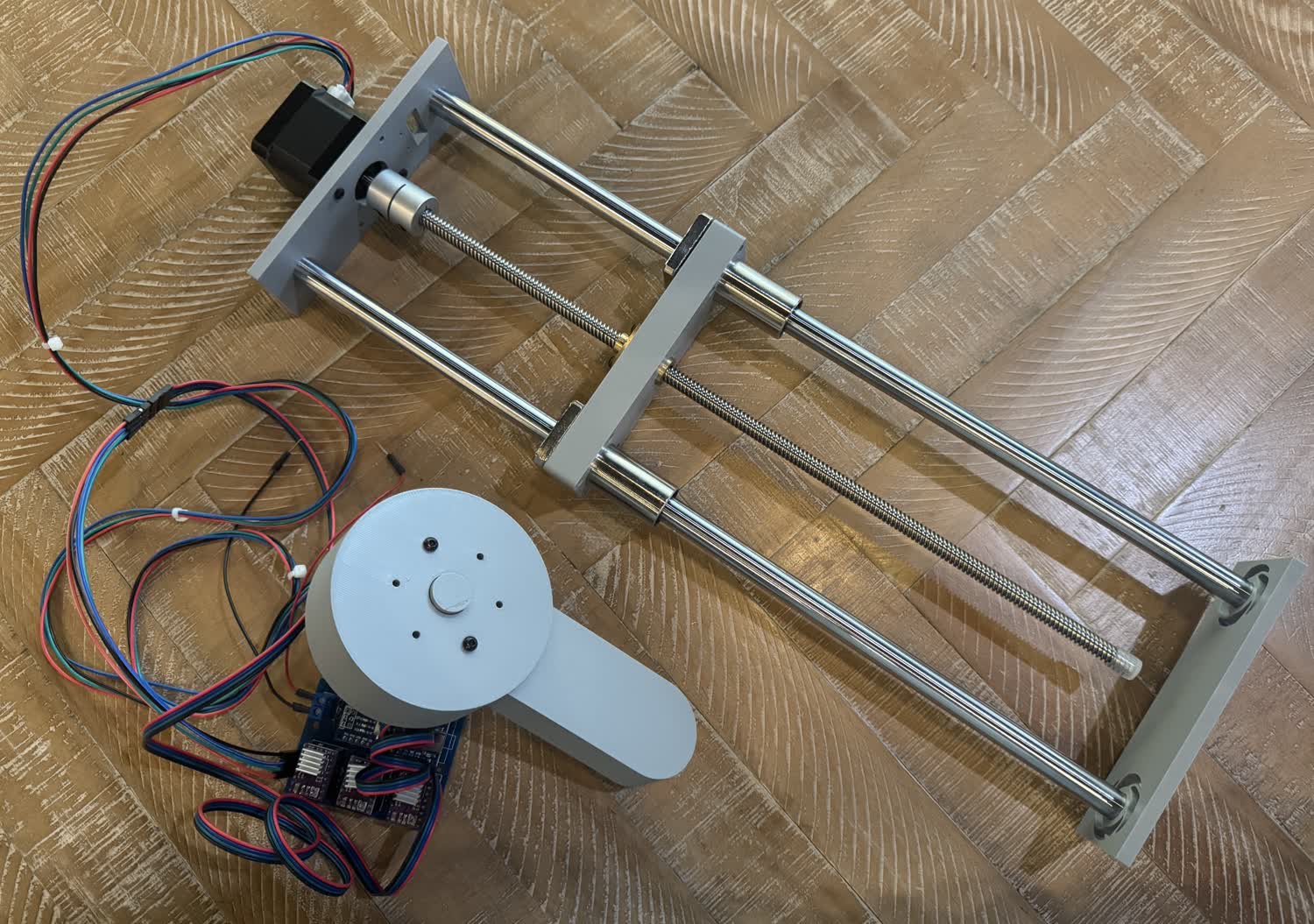
While testing the stepper motor, my printer finished up the prints and I went ahead and assembled the first version of the linear actuator.
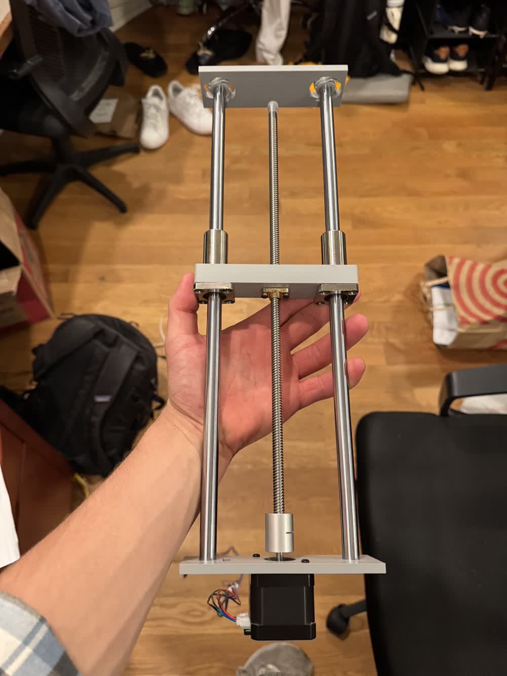
While its definitley crude, it very much works and serves as a great stepping point for moving forward. I want to make a more robust mounting system for the linear rods as opposed to simply being press
fits on both ends. I also of course need to add the actual platform that will allow for attacing other components. I also need to add the ranging system and position control system. I was going to try but
when I was wiring up everything onto a breadboard, I accidentally plugged both 5V and gnd on my VL53L1X into 5V and then I was no longer able to find it on the I2C channel.
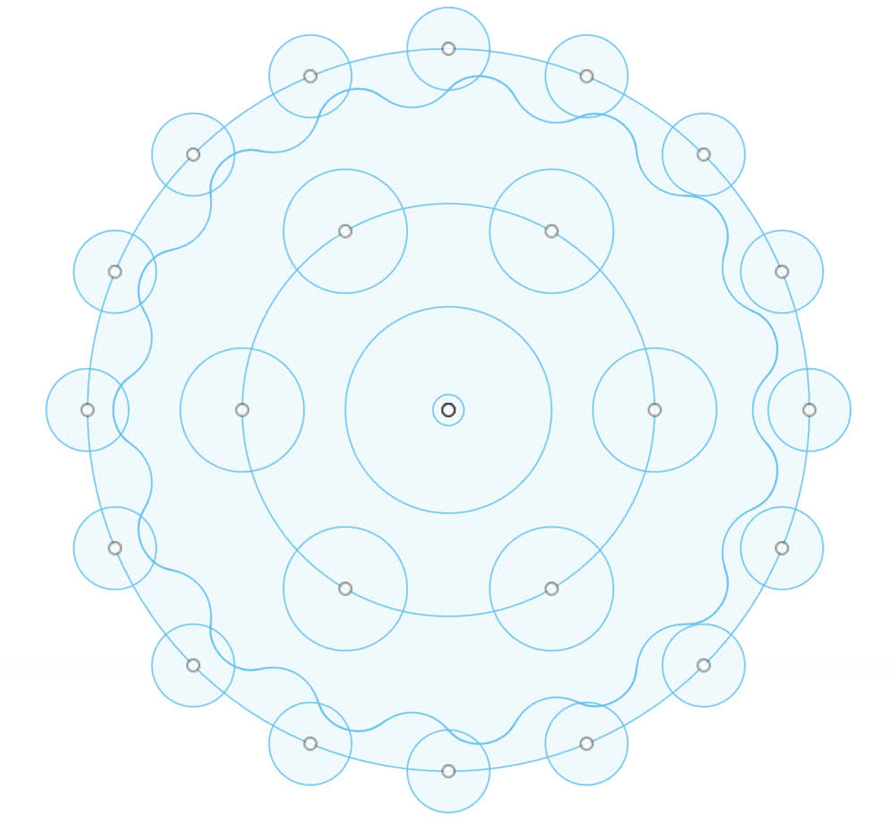
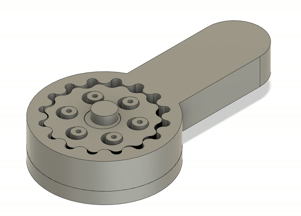
Next, I wanted to try and design a cycloidal drive. If you don't know what a cyloidal drive is, I highly recommend watching this youtube video
from 3D Printer Academy. In short, a cycloidal drive is a method of gear reduction that offers high gear reduction in a compact volume with little to no backlash. I found a bunch of useful
resources to try and get a grasp of what exactly was going on with in the mechanism so I could actually move forward and design one.
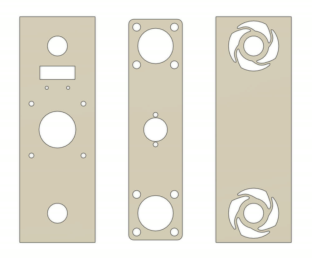
In the How to Mechatronics link, you can find the equations of curves needed to draw the cycloidal shape. It turns out that Fusion does not offer the option to actually draw equation based curves and so I tried jumping into solid works and it also was not behaving well so I tried something completely different. I jumped into a chat with ChatGPT and had it write a python script that, given all the desired parameters, generates a new DXF file that draws all the important features of the cycloidal drive that you can then import into whatever CAD program you want to use. This has proven to be super useful and I highly recommend trying it out. I've added the script below. For example, using the command below and providing the parameters:
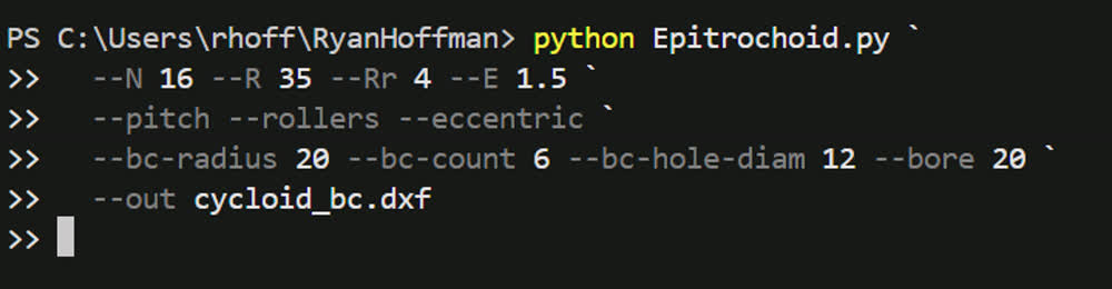
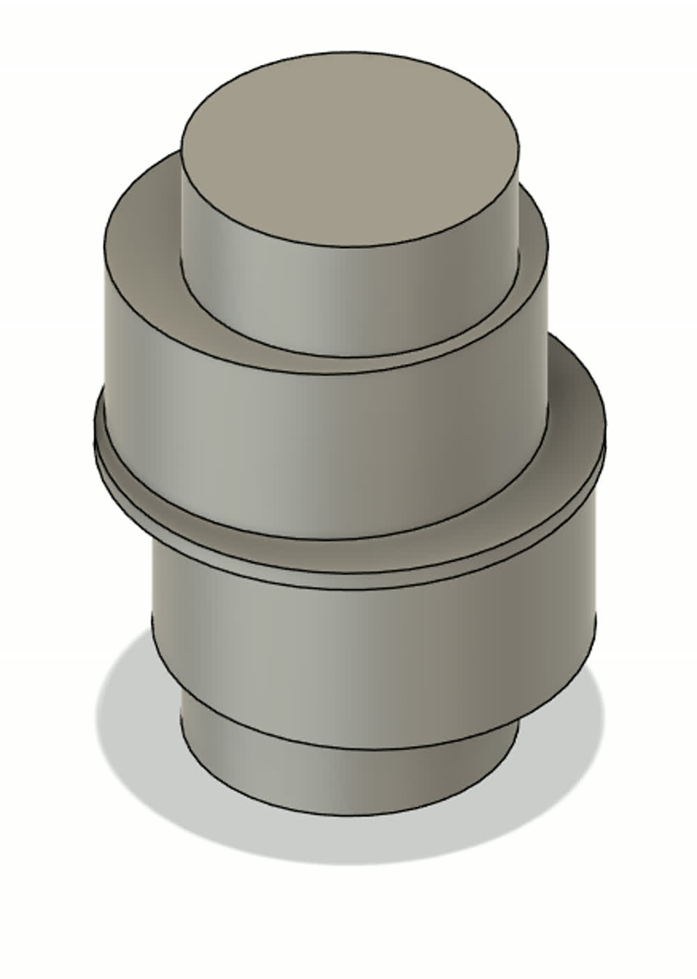
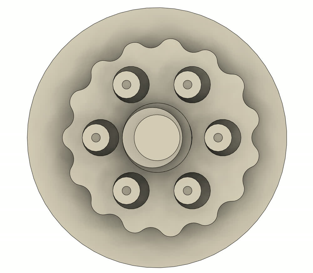
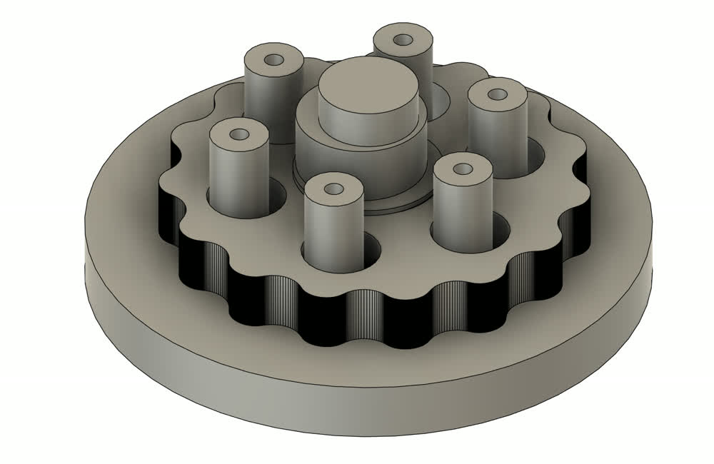
With the hardest part of the design now solved, I was able to quickly model the components to make a proof of concept cyloidal drive:
Measuring Power Consumption
I bought one of the power meters that Neil showed in class on Amazon and the DC Bench Top power supply that I have shows the wattage that it
is outputting. In the video shown below, you can see that the stepper and driver are drawing anywhere from ~6.2-7.4 watts. The variation comes
from the change in current draw from the motor as it rotates or holds its position. I use the power meter plugged into my comuter to measure the power
draw of the micro controller itself which was about .25 watts.
Thoughts and Reflection
I think this week was pretty successful! In terms of the goals that I outlined on my final project page for the week, I accomplished most of them!
I modeled and have functioning versions of both the linear and rotational actuators. Yes, they are crude, but I have time to move
forward and revise them. The only thing that I did not accomplish was to successfully drive a stepper motor with a DRV8428. I have
milled and soldered all of the components onto the PCB, I have just yet to test it which I am planning on doing later this week.
I was super pleased with the script that ChatGPT created for generating those cycloidal drives, I think it can be a super useful tool. It also
makes me curious about what other scripts I could try and make to help simplify the project and or documentation. I have been thinking about trying to
modify Camron's python script for image compression to compress any kind of file in the folder so videos, pngs, jpgs could all be converted in one go.
Moving forward, I want to try and revise the model of the actuators and get finalized versions so I can begin working on the attachment system and controls system.