The first challenge of the week was to figure out how to use gitlab for documentation. Last time I tried this I treated gitlab as a fancy pdf displayer, but this time around, I wanted to really learn how to make websites. I started out by changing some text on my HTMAA site.
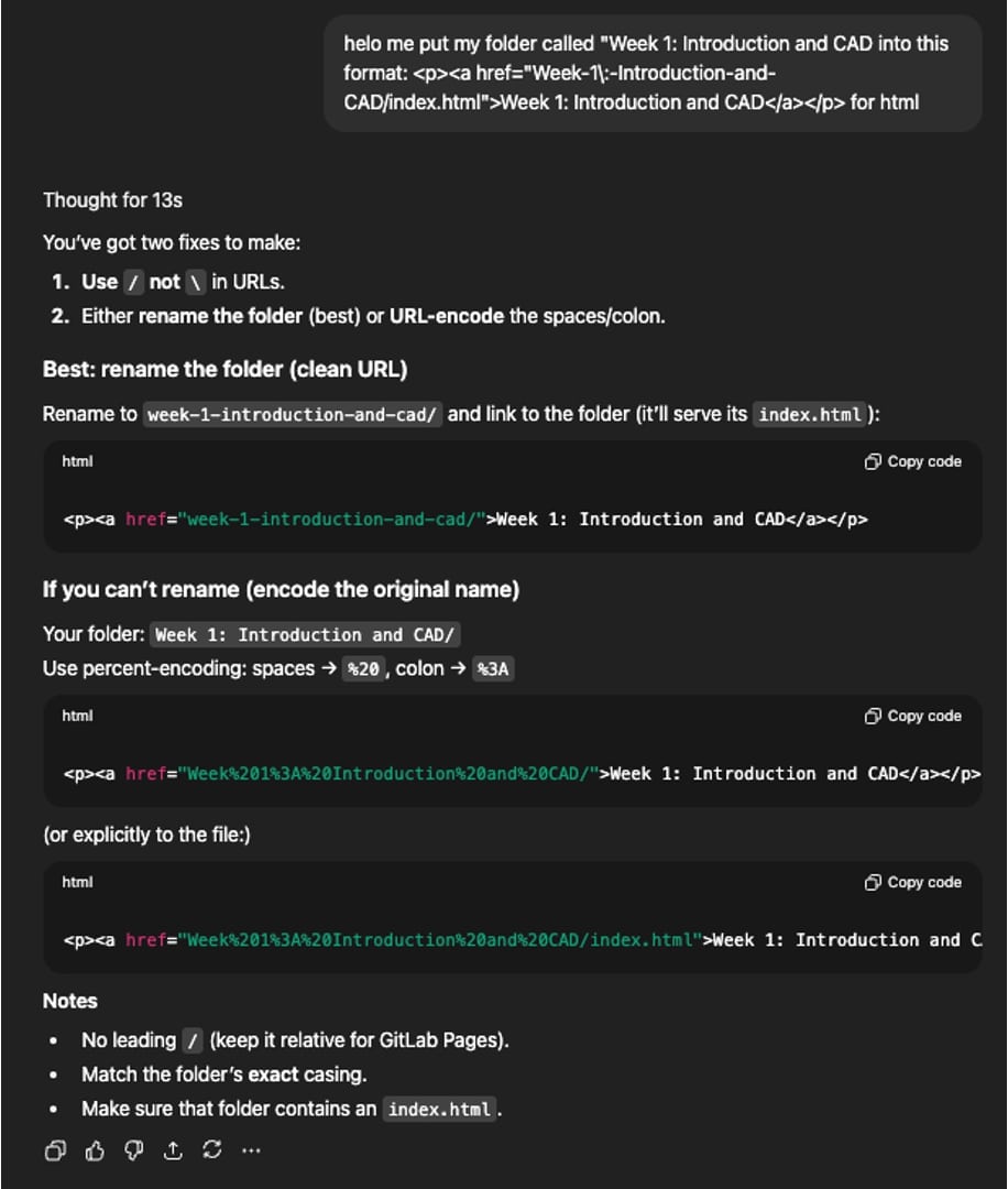
Next I added folders for the first two weeks, converted my images into jpgs using this png to jpg converter, and referenced lots of other students' pages to help with troubleshooting the html. After an extremely frustration-inducing formatting fiasco, I finally got things figured out. Major shoutout to Romeo Giudici who had some code in his repo that helped me figure out that mine wasn’t working. Absolute file paths don't work here I learned. Also shoutout to ChatGPT which helped me reformat my filepaths since my rash decision to use special characters “:” and “-” as part of my folder names was seemingly permanent, and gitlab doesn’t like that one bit.
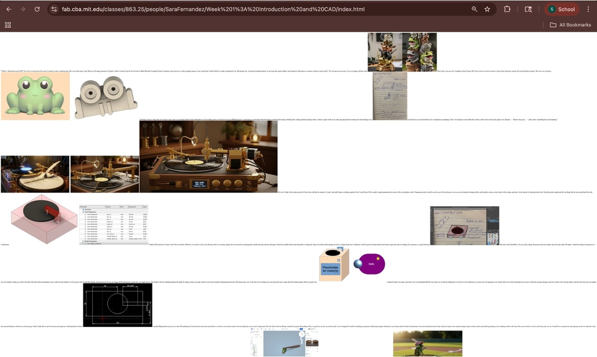
As you can see below, there were several additional issues included resizing images and getting them to display where I wanted them to. It was kind of a mess.
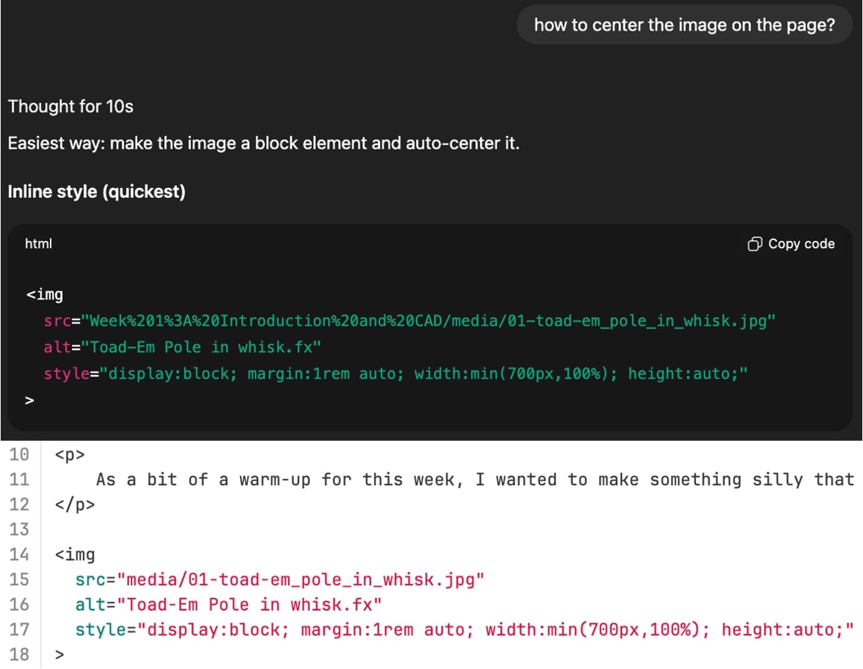
Again, ChatGPT helped me here with modifying things like image size, image position, title formatting, video insertion, and line breaks. I typically asked ChatGPT, "would this work?" and it would respond with some complicated options and some simpler ones. I opted for the simpler ones for now to keep the html consistent. The site looks okay now and it works, but I would like to spend some time later on making it look nicer. I went through a couple git tutorials but will need to get more familiar with the vocabulary and syntax before I opt to do things completely locally.
Next I will be adding some progress related to laser cutting and vinyl cutting. I have been sick so will get to that on Monday. More designing to happen today!
As a reminder, here is the group assignment: do your lab's safety training characterize your lasercutter's focus, power, speed, rate, kerf, joint clearance and types individual assignment: cut something on the vinylcutter design, lasercut, and document a parametric construction kit, accounting for the lasercutter kerf, which can be assembled in multiple ways, and for extra credit include elements that aren't flat
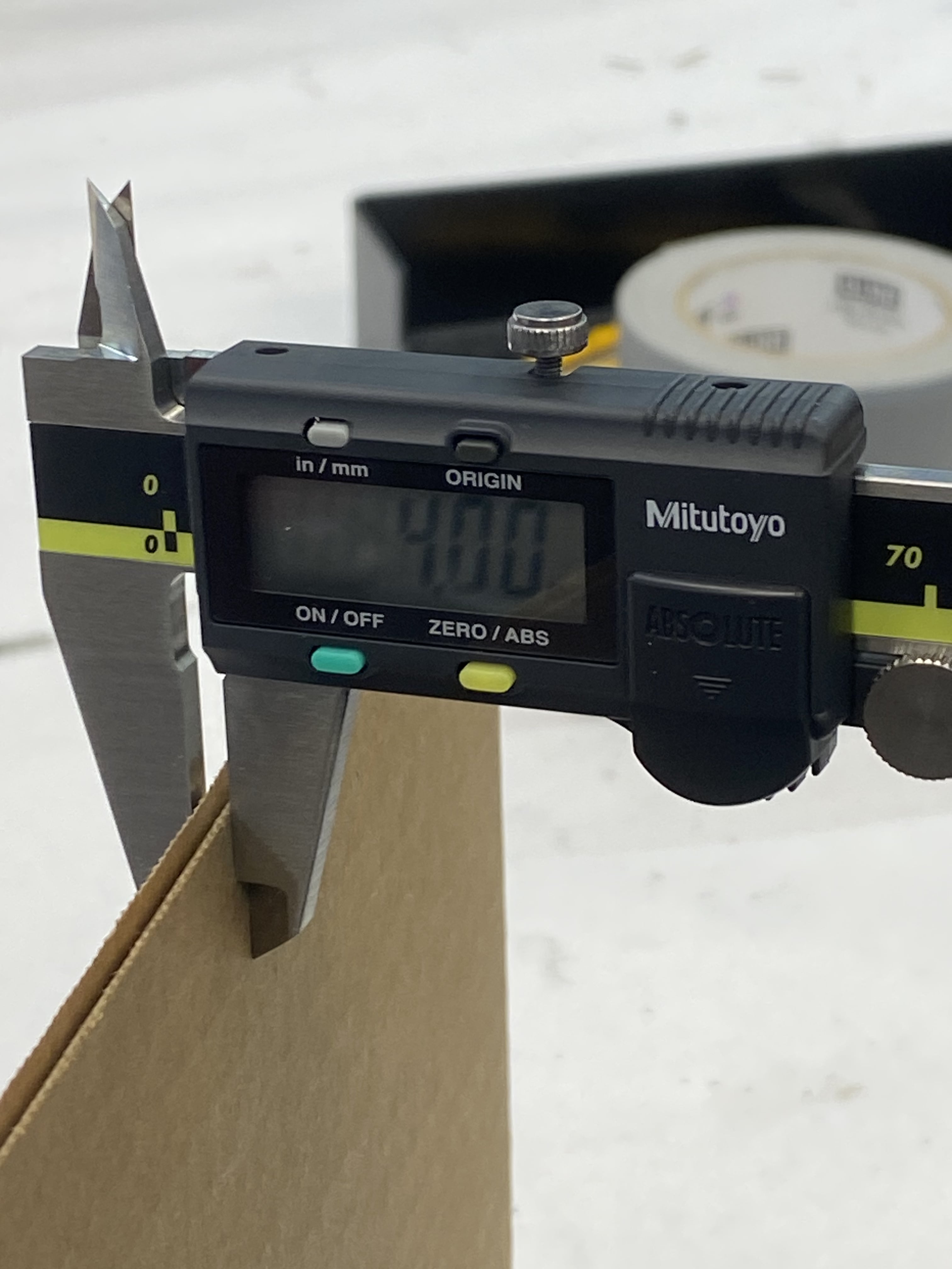
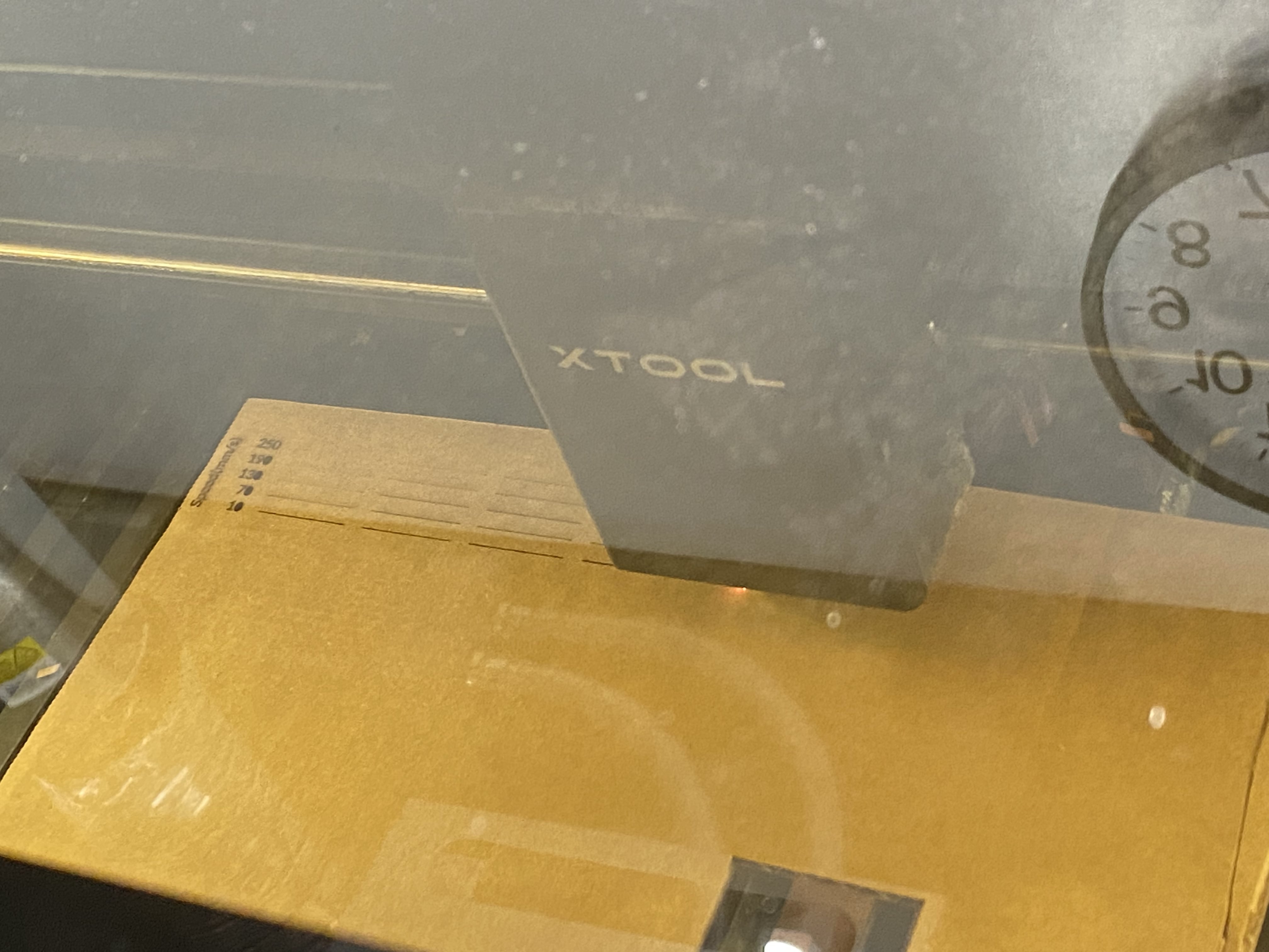
Dimitar and I met up to go through the group assignment together. We started with the xTool P2. We measured the cardboard thickness to be 4 mm, corroborated with Ceci's measurements. Because of slight bowing of the cardboard, the auto focus measured 4.2 mm.
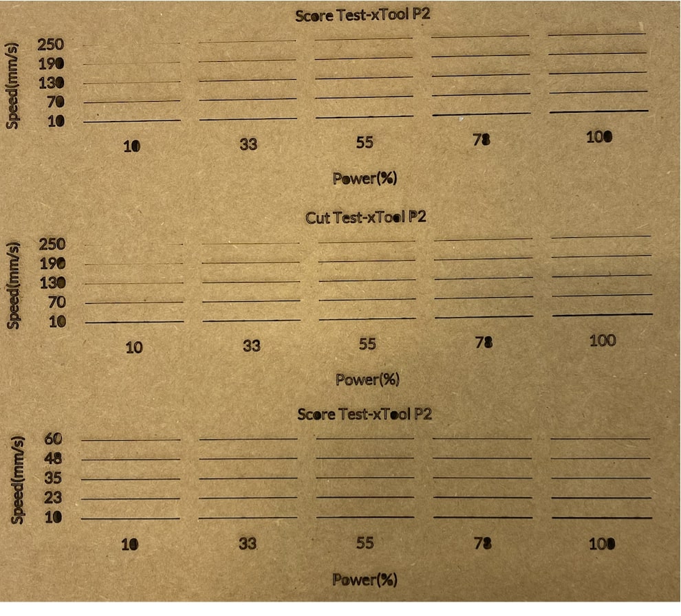
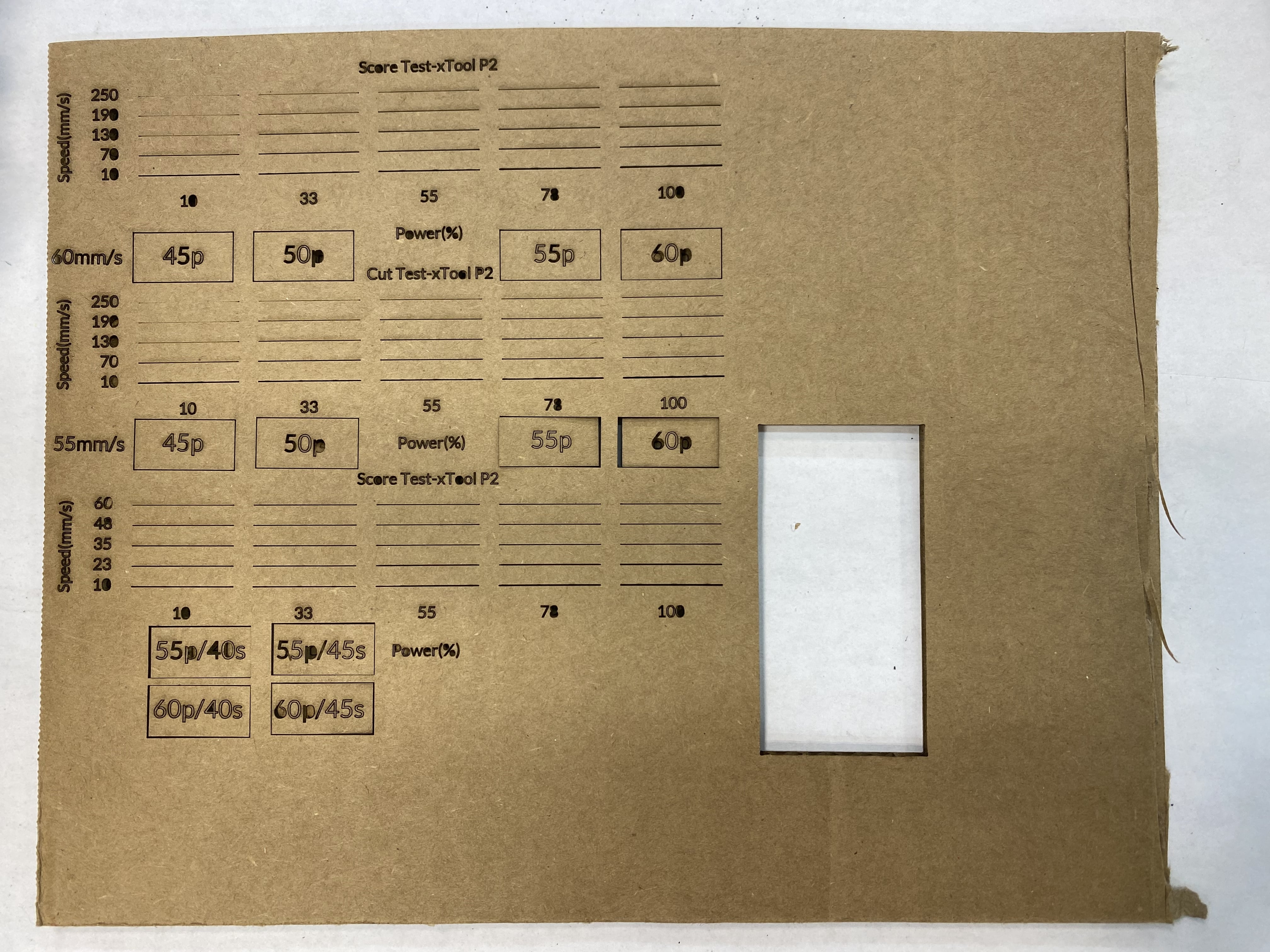
We started doing a test array of 25 mm lines using "score" and then used "cut" when we realized. After this we tried cutting a test array honing in on the most promising parameter values where cutting had been successful previously. This was between 10 and 60 mm/s.
Following this, we more granularly adjusted parameters. We wanted to be economical with our space so made the next cuts in unmarked positions within the same area as the previous cuts. The first set was testing 60 mm/s at powers 45, 50, 55, and 60. Then we tried decreasing the speed a bit to 55 mm/s, noticing that the vertical cuts were less clean than the horizontal ones, meaning either a slower speed or higher power would be needed.
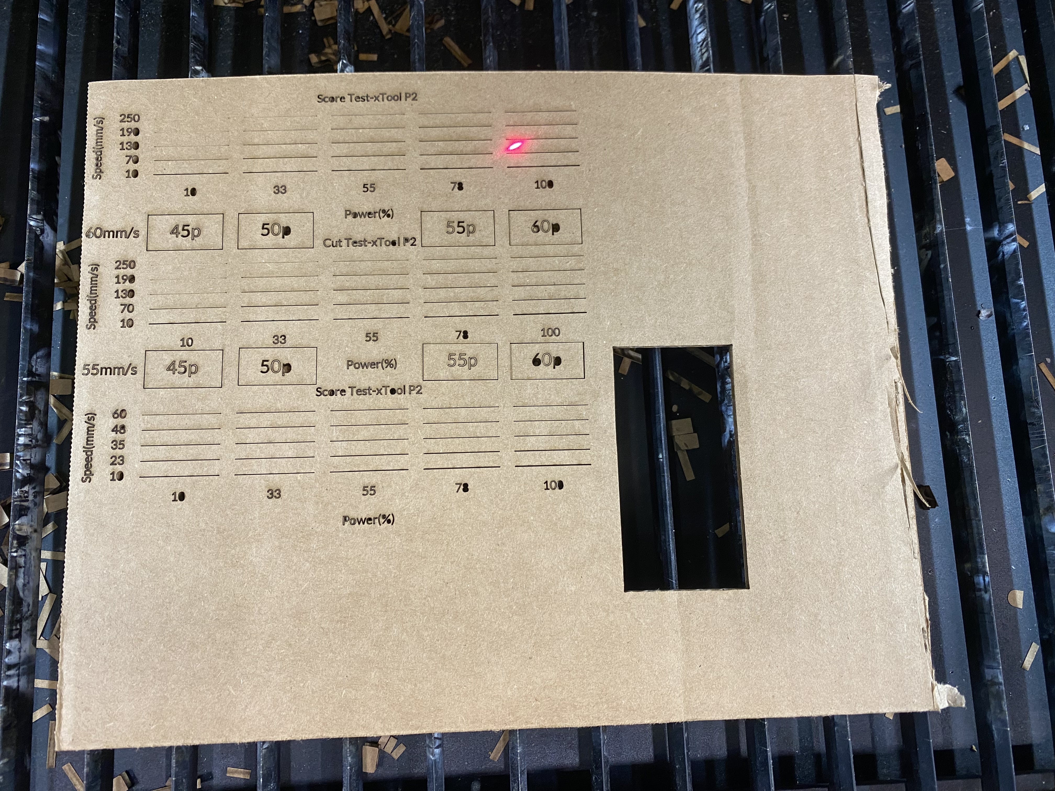
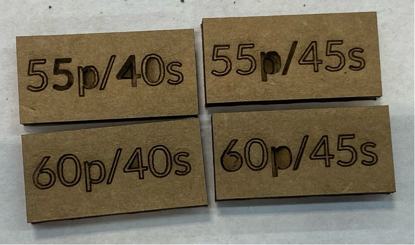
Since the rectangles did not seamlessly disconnect, we tried a 2x2 matrix of narrowed parameters: power of 55 and 60 with speed of 40 and 45. While all of these were removable, only 60% power and 45 mm/s speed cut out entirely on its own, so we deemed that to be the winner!
Here are the cutouts. We measured the kerf to be 0.1 mm using a caliper, which was corroborated by Ceci's numbers.
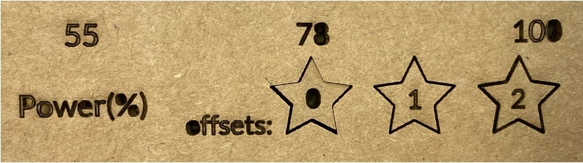
Next we tested the focus offset. We found that 0 was best. 1 and 2 had increasingly bigger kerfs as indicated by the darker outline, most apparent on 2.
Now that everything was characterized, I opened Fusion 360 to design parametric joints. Initially the delta (amount I changed their widths by) was one thou. However, this seemed to be too small of a difference since interlocking pieces were pretty loose.
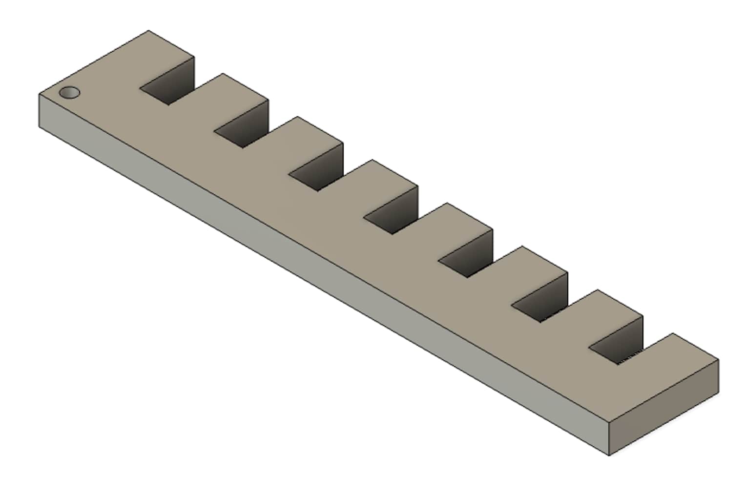
Here they are after discarding the cut away cardboard and interlocking the smallest notch of one, with the largest of the other. The circle indicates which side's notches has smaller widths.
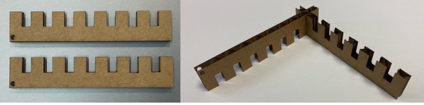
The next step is to iterate on this and test out other types of notches.
Referring to this joints image and former Fab Class student Gabriella Perry's site, I made my own. Here are a few of these.
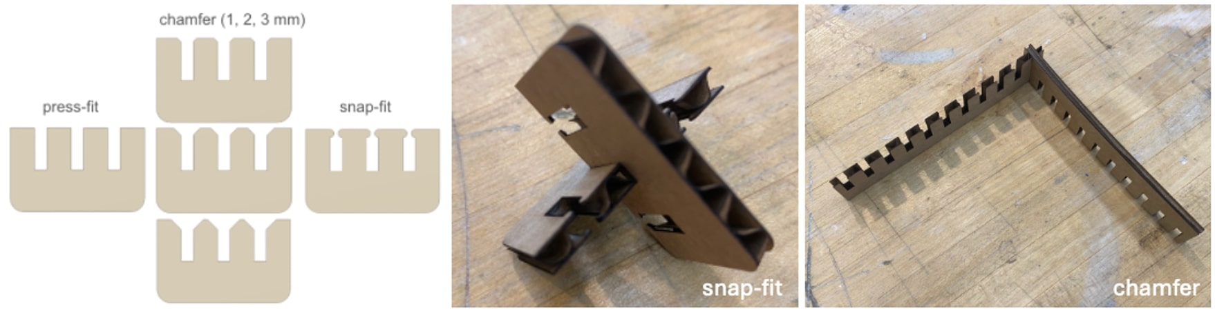
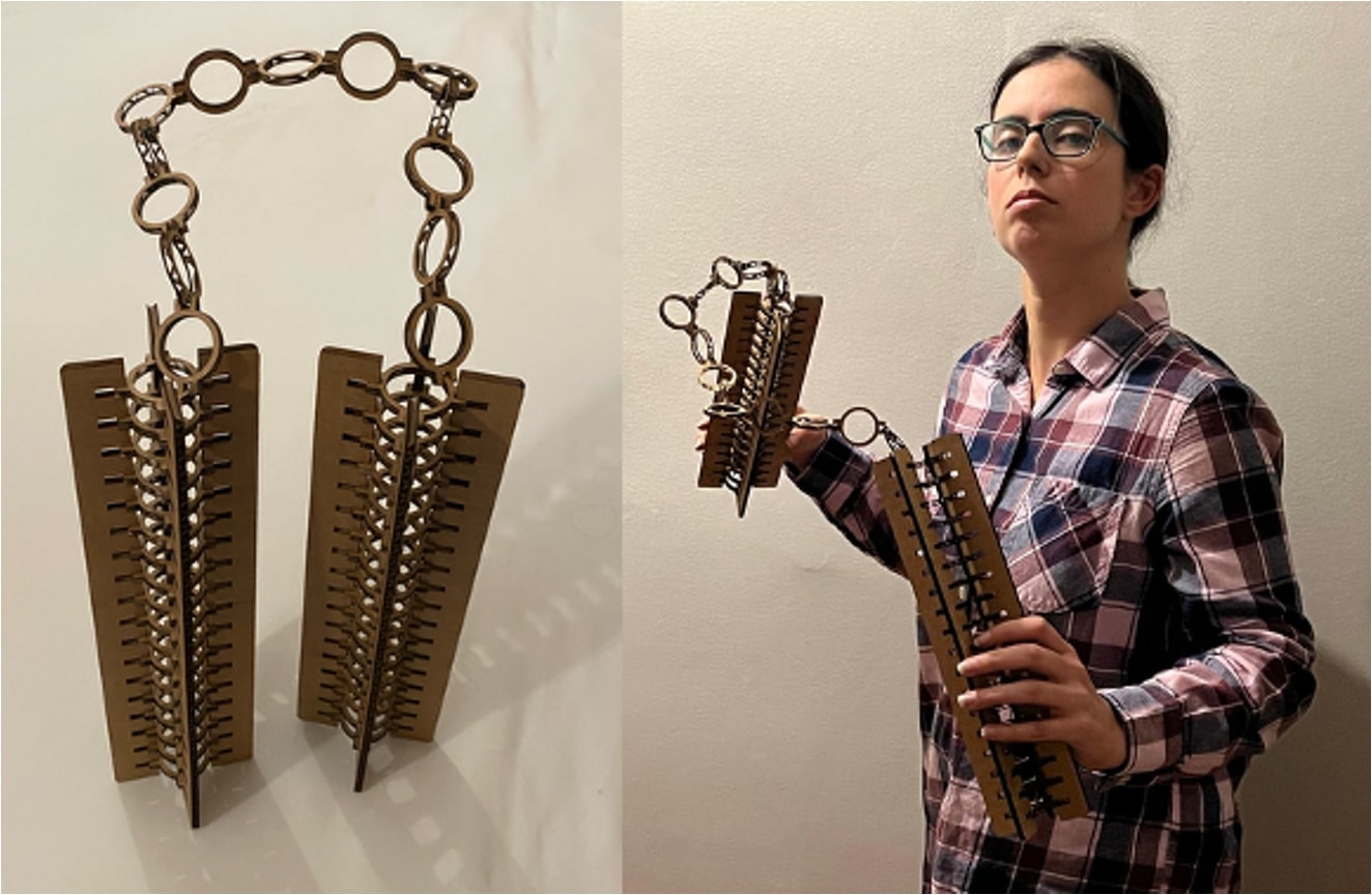
The chamfer (we cut the one Dimitar designed) worked way better than the press-fit from before. After this, I thought about how to break up my idea for what to make into smaller components to tackle. Since I trained in martial arts growing up, I have had a long-term facination with nunchucks as an artistic implement used in performance and symbol of dedication to one's craft. First was the chain links, simple circular interlocking pieces. I started with my chamfer joint and ended up going with the press-fit since I wanted the chain links to not easily separate. I went through many, many iterations here and maybe spent too much time being indecisive. Here are some of the rejects from this design session.
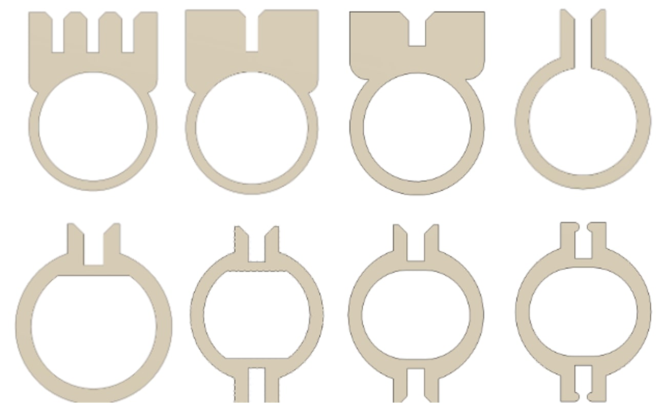
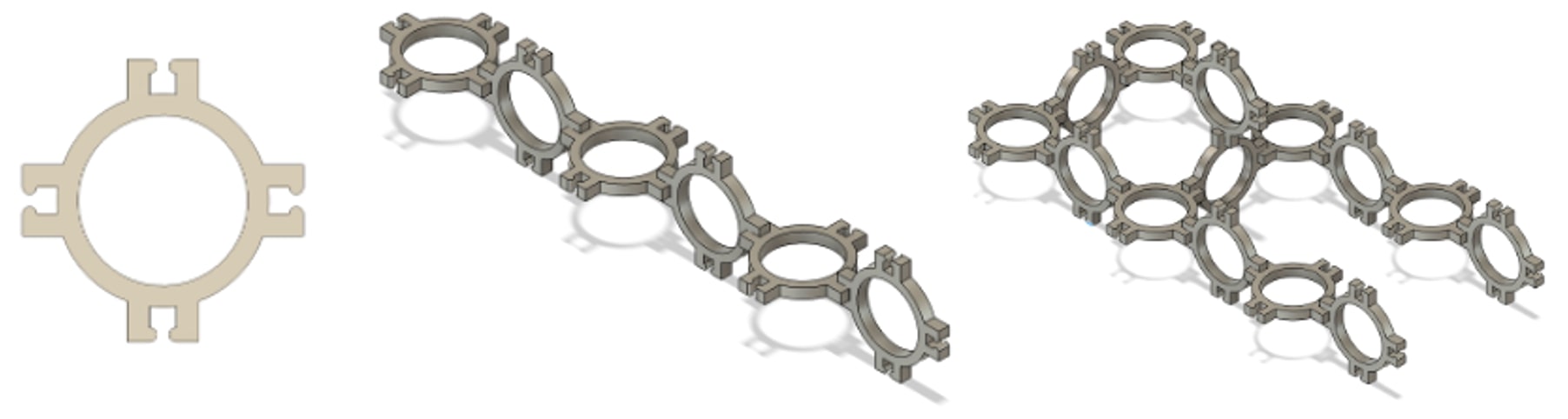
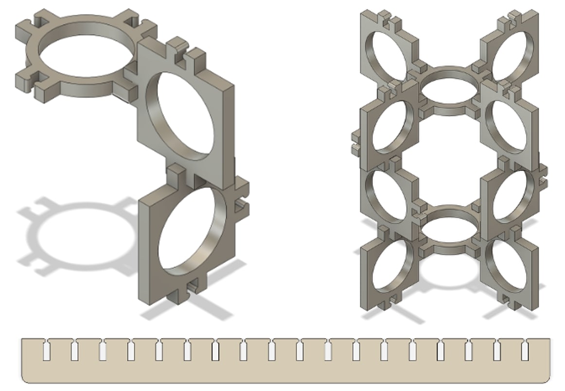
I landed on using this version of the chain link which used four press-fit joints, one at each cardinal direction. I messed around in Fusion 360 a bit to arrange them how I wanted. They seemed to work well as a chain, and presumably can also be used to build any wacky structure like the one on the right.
Next I had to think about the second component of the nunchucks, the handles. I had hoped to make them out of the same circular links used for the chain, with the addition of an external connector of some sort. Initially I wanted to have a bunch of smaller ones interlocking, but I realized flipping every other one to align the joints was not going to work if I wanted the handle to be consistent across its length. After looking at these types of forms on my computer for a while, including the rightmost one which reminded me of a biblically accurate angel, I decided to switch to a longer piece. I ended up modifying my original joint test piece design, creating a rectangular pattern to do so. This is the bottommost image below.
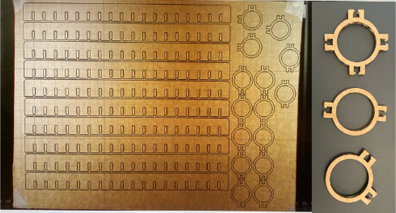
Then I got ready to laser cut these. Unfortunately, the cardboard piece Dimitar and I had characterized previously was not the same type as the one set aside for HTMAA use. Because of this, we needed to recharacterize. A few different power/speed combinations worked well, so we went for something in the middle, 80% power at 20 mm/s. It was rather amusing to us, given the 80:20 rule Neil mentioned in class previously. It really did turn into more of a 95:5 rule this time around. Anyway, I cut my large cardboard piece into much smaller pieces suitable for use in the xTool P2 with some help from Dan and then waited my turn in line. I think many of us were surprised by how long the cutting process would take. I am glad I was able to cut out my pieces before it got to be too late.
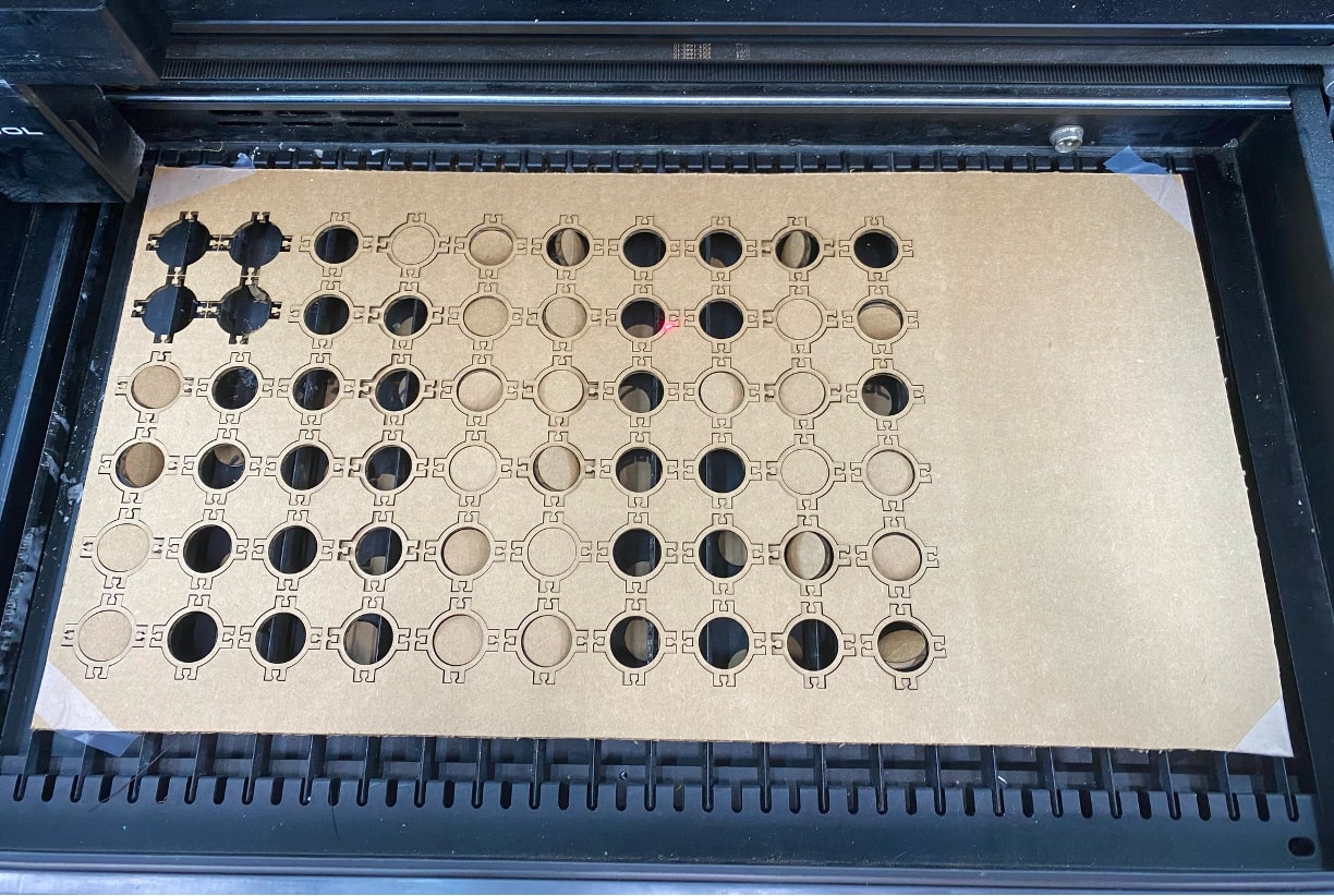
After I cut out the links, I let Matti cut out his pieces to make a flower. It turned out great! As I was waiting, I decided to make some slight modifications to my chain link design. Since I wanted to make the chain look a little neater, I made two additional pieces. One had joints only on the top and bottom, and the other had joints on two perpendicular sides to serve as a corner for added stability. I finished cutting my pieces and ended up with this for the second cut.
Then it was time for assembly.
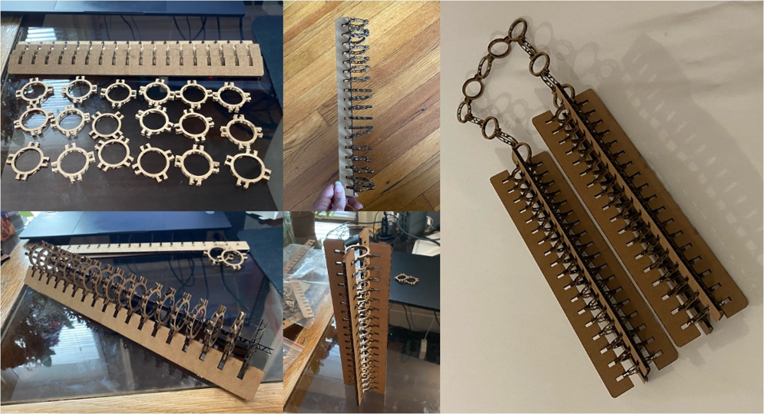
I think it turned out pretty great! I was happy that they were able to be freestanding as well. The links weren't super easy to disconnect initially, but with the pull of the handles, they didn't really hold up as well as I would have liked. Next time around, I'd like to make these connections stronger. Perhaps I'll make the nunchucks smaller too. For now, these will be a desk ornament (albeit a very cool looking one).
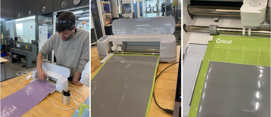
This week I also did some vinyl cutting on the Cricut Maker 3. Dan helped Dimitar and I get started and we downloaded the Cricut software. We made some alignment error in our first attempt, seeing as the oval shape only cut into part of the gray vinyl we had loaded.
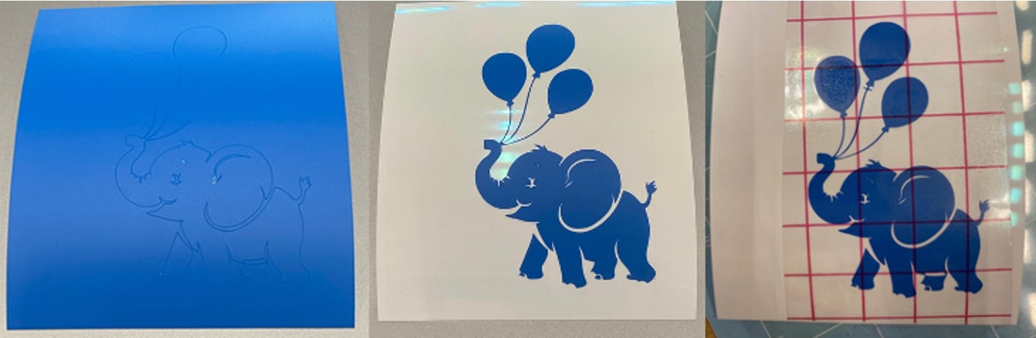
Later in the day I tried again with a preset design and it worked. I had trouble getting the transfer tape to pick up the image, so I left it as-is.
I tried making my own design in LibreOffice Draw, but I quickly realized my drawing skills on there were sub-par. I made a very strange looking dog(?) that I decided to vinyl cut. I like it personally but I admit it is very odd-looking.
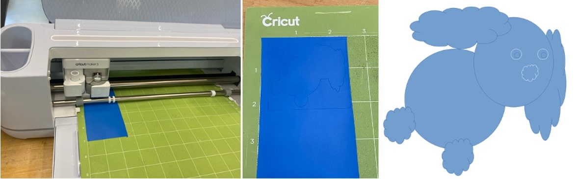
It didn't cut out the white parts how I expected it to, so I switched to PowerPoint to make a better design. My grandma calls me her "mariposita," or butterfly, so I wanted to make one for her. Here it is next to the throw pillow she gave me last time I visited.
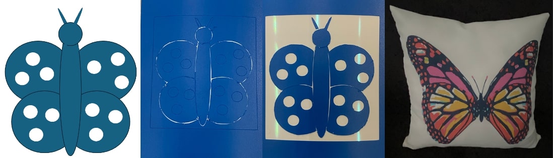
I really like how it turned out. I suspect the overcutting was due to me including outlines in the shapes I used to construct the butterfly. It's a good learning of something to change for next time. This has been a very fun yet busy week. I look forward to the next!