System Architecture Overview
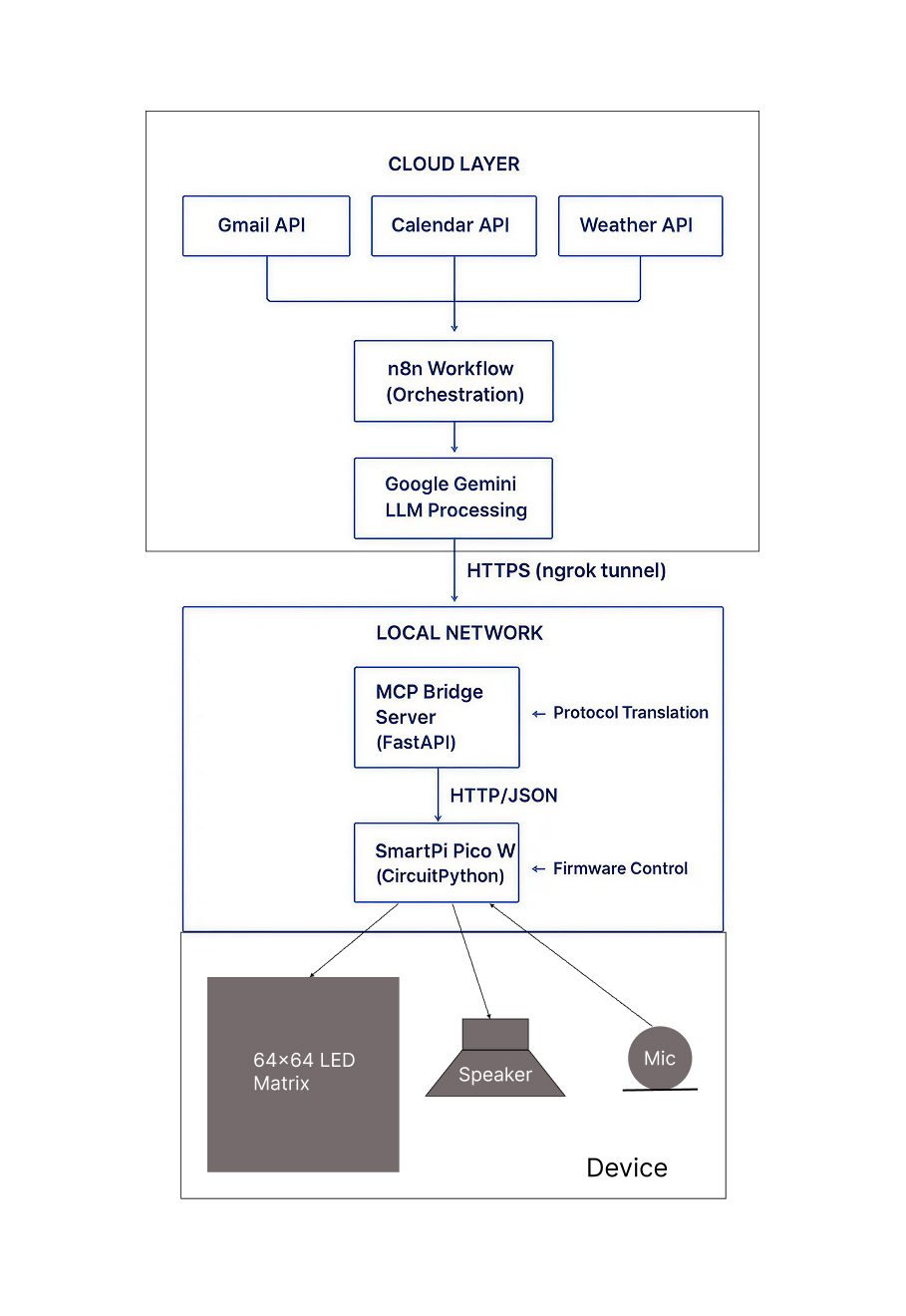
The SmartPi Assistant's software architecture is built around three core principles: modularity, protocol-driven communication, and edge-cloud hybrid intelligence. The system bridges cloud-based LLM processing with local embedded control, creating a responsive ambient intelligence platform.
High-Level Architecture
1. Firmware Architecture (CircuitPython)
Core Design Philosophy
The firmware is designed as a lightweight HTTP listener with a focus on reliability, modularity, and real-time display performance. Running on CircuitPython allows rapid prototyping while maintaining low-level hardware control through the RP2040's dual-core architecture.
Key Components
- WiFi Manager — Handles connection lifecycle with auto-reconnect
- HTTP Server — Lightweight web server (adafruit_httpserver)
- Message Queue — Circular buffer with priority sorting
- Display Renderer — HUB75 LED matrix control with themes
- Audio Subsystem — I²S amplifier integration (optional)
Message Queue System
The message queue implements a priority-based circular buffer that automatically sorts incoming messages by urgency (urgent → important → normal) and rotates through them with configurable display time.
Queue Design Properties
| Property | Value | Rationale |
|---|---|---|
| Max Size | 50 messages | Balances memory constraints (264KB RAM) with practical capacity |
| Rotation Time | 5 seconds | Optimal for readability without feeling rushed |
| Update Mode | Replace entire queue | Atomic updates prevent partial state issues |
| Priority Order | Urgent (0) → Important (1) → Normal (2) | Ensures critical information displays first |
Display Rendering Pipeline
The display subsystem leverages the rgbmatrix library to drive the HUB75 interface
with precise timing control. The rendering pipeline includes:
Text Input → Word Wrap → Theme Application → HUB75 Output

1. Text Processing:
   - Automatic word wrapping to fit 64×64 matrix
   - Maximum 5 lines per message
   - Truncation with ellipsis for overflow

2. Theme System:
   - 5 predefined color schemes (calendar, email, weather, slack, neutral)
   - Foreground, background, and accent colors
   - Dynamic color switching based on message type

3. Hardware Acceleration:
   - CPU overclocked to 250MHz for smooth refresh
   - Bit depth: 4-bit (16 color levels)
- Serpentine scanning for uniform brightness- Rapid prototyping and iteration
- Rich library ecosystem (adafruit)
- Easy debugging via serial console
- Sufficient performance for 64×64 matrix at 60 FPS
HTTP Endpoints
The firmware exposes three REST endpoints for message management:
| Endpoint | Method | Purpose |
|---|---|---|
/messages |
POST | Receive batch of messages with priority and theme |
/status |
GET | Query device state (queue size, WiFi status, IP) |
/clear |
POST | Clear all messages from queue |
2. n8n Workflow with LLM Integration
Workflow Architecture
The n8n workflow orchestrates data collection, LLM-based summarization, and delivery to the SmartPi device. It operates on a scheduled trigger model, periodically pulling data from multiple sources and pushing processed results. The visual workflow editor makes it easy to understand and modify the data flow.
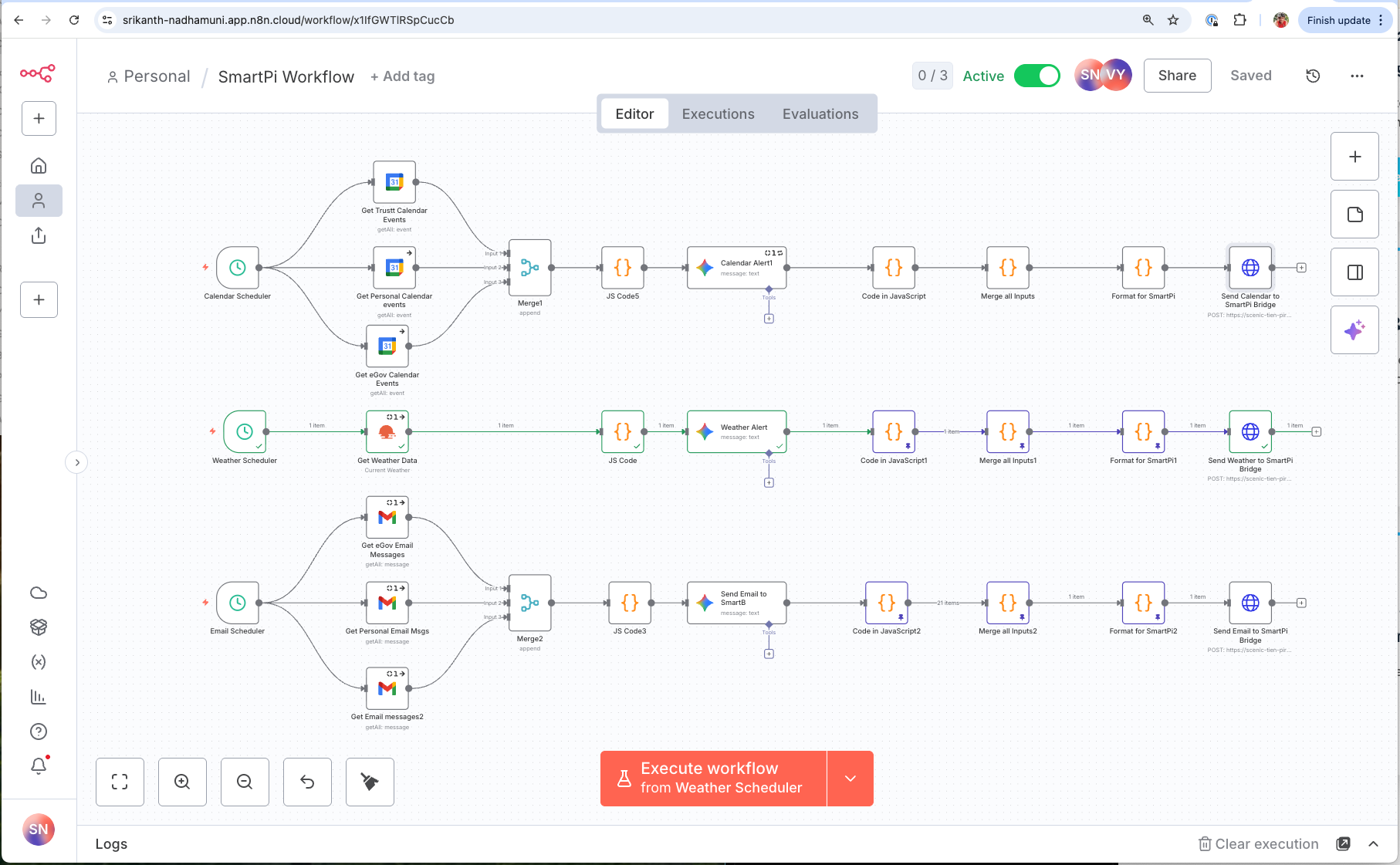
Understanding n8n Workflow Components
1. Trigger Nodes: Starting the Workflow
The workflow begins with a trigger node that determines when execution starts. In the SmartPi workflow (shown on the left with a cursor icon), I use a manual trigger labeled "When clicking 'Execute workflow'" that allows on-demand execution for testing and immediate updates.
Trigger Options Considered
| Trigger Type | Use Case | Configuration |
|---|---|---|
| Manual Trigger | Testing and on-demand updates | Click button to execute |
| Schedule (Cron) | Automatic periodic updates | Every 15-30 minutes, or hourly |
| Webhook | Event-driven execution | React to external events (calendar changes) |
For production deployment, a schedule trigger running every 15-30 minutes would keep the display continuously updated.
2. Data Source Nodes: Fetching Information
After the trigger fires, the workflow branches into three parallel paths, each connecting to different data sources:
- Google Calendar nodes (shown as calendar icons): Authenticate with OAuth2 and fetch upcoming events from three calendars (trust calendar, personal calendar, eGov calendar). Return structured JSON with event titles, times, locations, and attendees.
- Weather API node (shown as weather icon): Makes HTTP request to OpenWeatherMap API, passing coordinates for Cambridge, MA. Returns current temperature, conditions, humidity, and forecast.
- Gmail nodes (shown as email icons): Connect via OAuth2 to Gmail API and fetch recent unread messages from three email accounts. Return sender, subject, snippet, and timestamp for each message.
3. JavaScript Code Nodes: Data Processing
The JS Code nodes (shown as {} icons throughout the workflow) execute custom JavaScript
to filter, transform, and format raw API responses. These are where the intelligence happens—turning verbose API
data into concise, actionable messages optimized for the 64×64 pixel display.
Example: Weather Branch JS Code
// Access weather data from OpenWeatherMap API
const temp = $input.item.json.main.temp;
const conditions = $input.item.json.weather[0].description;
const location = $input.item.json.name;

// Add contextual advice based on temperature
let advice = "";
if (temp < 40) {
  advice = "Wear a heavy jacket!";
} else if (temp < 55) {
  advice = "Bring a light jacket.";
} else if (temp > 85) {
  advice = "Stay hydrated!";
} else {
  advice = "Enjoy the weather!";
}

// Format for SmartPi display (max 55 chars)
return {
  json: {
    text: `${Math.round(temp)}°F ${conditions} - ${advice}`,
    theme: "weather",
    priority: "normal"
  }
};
Example: Calendar Branch JS Code
// Get all calendar events from multiple sources
const events = $input.all();

// Filter for events in next 2 hours
const now = new Date();
const twoHoursLater = new Date(now.getTime() + 2 * 60 * 60 * 1000);

const upcomingEvents = events
  .map(item => item.json)
  .filter(event => {
    const eventTime = new Date(event.start.dateTime);
    return eventTime >= now && eventTime <= twoHoursLater;
  })
  .sort((a, b) =>
    new Date(a.start.dateTime) - new Date(b.start.dateTime)
  );

// Format most urgent event
if (upcomingEvents.length > 0) {
  const event = upcomingEvents[0];
  const eventTime = new Date(event.start.dateTime);
  const timeStr = eventTime.toLocaleTimeString('en-US', {
    hour: 'numeric',
    minute: '2-digit'
  });

  return {
    json: {
      text: `Meeting: ${event.summary} at ${timeStr}`,
      theme: "calendar",
      priority: "urgent"  // < 2 hours = urgent
    }
  };
}

return { json: { text: "No meetings soon", priority: "low" } };
These JavaScript nodes provide complete programmatic control to implement business logic, apply conditional formatting, and prepare data precisely for the SmartPi's display constraints.
4. Merge Nodes: Combining Parallel Branches
The Merge nodes (shown as ⧓ icons) wait for multiple branches to complete
and combine their outputs. In the workflow:
- Merge1: Combines three calendar data sources into unified event list
- Merge2: Combines three email sources into unified message list
- Final Merge: Combines Weather + Calendar + Email outputs before formatting
This merge strategy enables parallel data fetching (reducing total execution time from 15+ seconds to ~5 seconds) while producing a single consolidated output.
5. LLM Message Generation Nodes
The "Calendar Alert", "Weather Alert", and "Email Alert" nodes (shown with colorful icons) use Google Gemini to generate final formatted messages. Each passes structured prompts to the LLM with specific constraints for length, format, and tone.
6. Format for SmartPi Node
The final "Format for SmartPi" JS Code node takes merged alert data and applies final optimizations:
- Text truncation: Limits messages to 80 characters max
- Priority sorting: Orders by urgency (urgent → important → normal → low)
- Theme assignment: Maps message types to color themes
- Deduplication: Removes identical messages
- MCP command construction: Builds final JSON payload
7. Send to SmartPi Bridge Node
The final "Send to SmartPi Bridge" node (shown as globe icon) makes an HTTP POST request to the MCP bridge server. Example payload:
{
  "tool": "push_messages",
  "args": {
    "messages": [
      {"text": "Meeting at 10:30AM with John", "theme": "calendar", "priority": "urgent"},
      {"text": "72°F Partly cloudy - Enjoy!", "theme": "weather", "priority": "normal"},
      {"text": "3 new emails from Sarah", "theme": "email", "priority": "important"}
    ]
  }
}- Easy to understand data flow at a glance
- Quick iteration and debugging (see data at each step)
- No deployment pipeline—changes go live immediately
- Built-in error handling and retry logic
- Extensive integration library (800+ pre-built nodes)
LLM Summarization Strategy
Google Gemini 2.5 Flash is used for real-time summarization due to its:
- Low latency (~2 seconds per request)
- Cost efficiency (free tier: 15 RPM, 1M TPM)
- Strong instruction-following capabilities
- JSON output mode for structured data
Prompt Engineering Principles
Each prompt follows a structured format optimized for the 64×64 display constraints:
Calendar Events:- Prefix: "C " (for Calendar)
- Urgency markers: URGENT (< 2 hours), IMP (today), none (later)
- Time format: 12-hour (e.g., "2PM")
- Max length: 55 characters
- Focus: Action or person involved
- Output: JSON with keys "cal_1", "cal_2", etc.
- Prefix: "E " (for Email)
- Priority: URGENT (time-sensitive), IMP (important), none (normal)
- Include: Sender's first name only
- Max length: 55 characters
- Focus: Key action or information
- Output: Plain text (one alert per email)
- Prefix: "W " (for Weather)
- Include: Temperature, condition, location
- Actionable: What to wear/bring
- Max length: 55 characters
- Removes duplicate messages (same text)
- Limits output to top 10 messages
- Ensures character limits are enforced
- Auto-detects theme from message prefix
3. Model Context Protocol (MCP) Design
Why MCP?
The Model Context Protocol provides a standardized way for LLMs and agents to interact with external tools and hardware. By implementing MCP, SmartPi becomes a first-class peripheral for agentic systems, enabling:
- Discoverability — Tools are self-describing via manifest endpoint
- Extensibility — New capabilities can be added without changing client code
- Interoperability — Works with any MCP-compatible client (n8n, LangChain, ChatGPT)
- Future-proofing — Aligns with emerging agent-hardware communication patterns
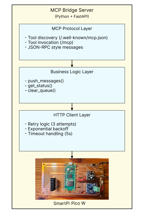
MCP Bridge Server Architecture
The MCP bridge acts as a protocol translator between high-level tool calls and low-level device commands. Built with FastAPI, it provides both MCP-compliant endpoints and direct HTTP endpoints for testing.
Defined MCP Tools
| Tool Name | Parameters | Purpose |
|---|---|---|
push_messages |
messages (array), timestamp (optional) | Send batch of messages to display |
get_status |
None | Query device state and health |
clear_queue |
None | Clear all messages from device |
push_messages handles batch
updates, priority sorting, and error recovery — the client doesn't need to understand
queue management internals.
Error Handling & Resilience
The bridge implements multiple layers of error handling:
- Network Timeouts — 5-second timeout with 3 retry attempts
- Exponential Backoff — 2n seconds between retries
- Graceful Degradation — Returns error status without crashing
- Logging — Comprehensive logging for debugging
4. Cloud-to-Local Network Connectivity
The Challenge: Bridging Internet and LAN
A key architectural challenge is enabling n8n Cloud (running on n8n's servers) to communicate with the MCP bridge (running on a local network). Traditional HTTP cannot work because:
- The bridge server runs on
localhost:5055(not publicly accessible) - NAT/firewall prevents inbound connections from the internet
- Port forwarding requires router configuration and exposes security risks
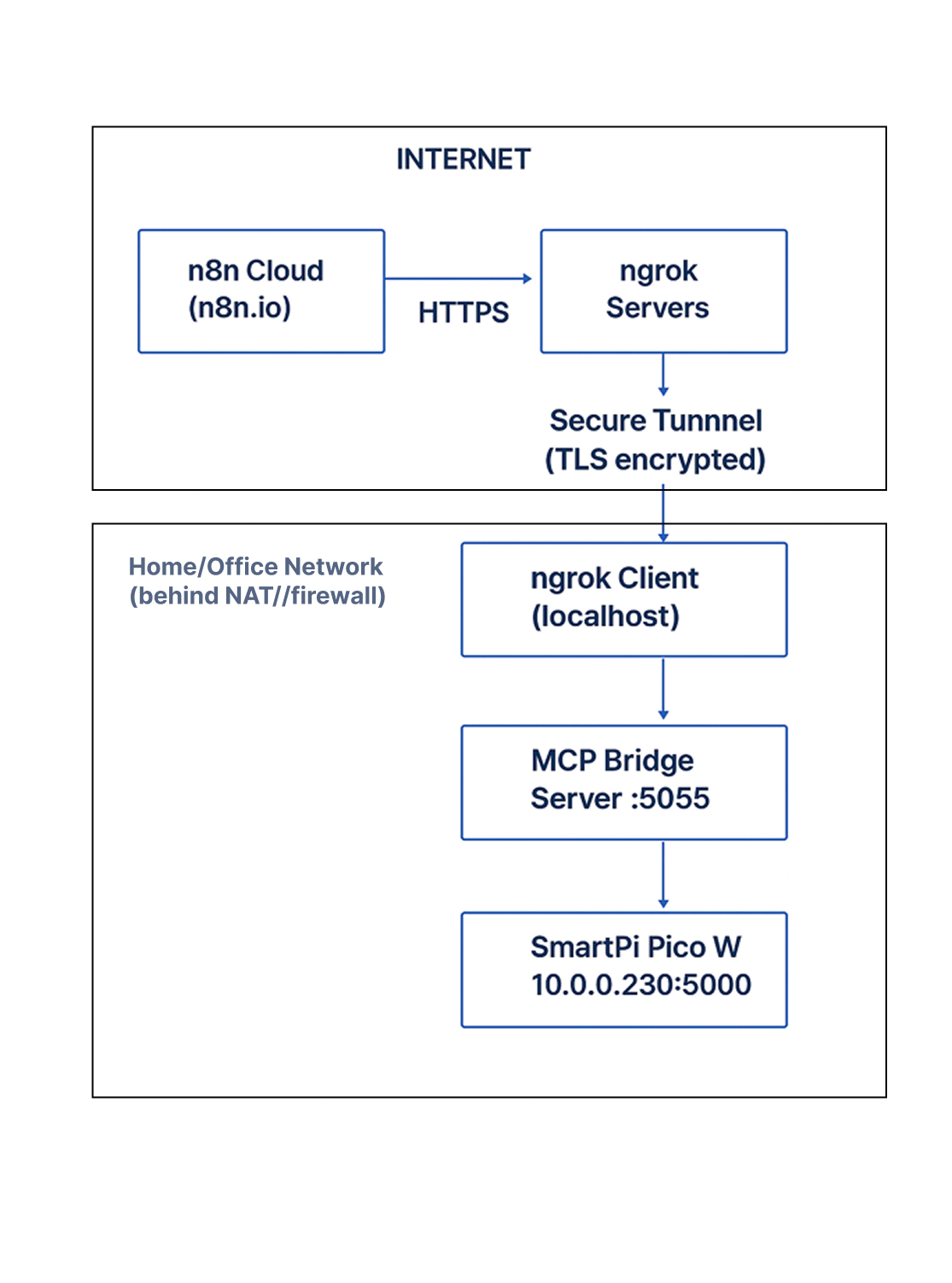
Solution: ngrok Secure Tunneling
ngrok creates a secure tunnel from a public URL to the local bridge server, enabling cloud-to-local communication without firewall modifications.
Connectivity Architecture
ngrok Configuration
# Start ngrok tunnel
$ ngrok http 5055

# Output:
Forwarding  https://abc123.ngrok-free.app → http://localhost:5055

# In n8n HTTP Request node:
URL: https://abc123.ngrok-free.app/mcp
Method: POST
Body: {"tool": "push_messages", "args": {...}}- All traffic is TLS-encrypted (https://)
- ngrok URL is randomly generated (hard to guess)
- URL can be regenerated or use custom domains (paid plans)
- Can add authentication layer in bridge server (future)
Alternative: Self-Hosted Tunnel
For production deployments, alternatives to ngrok include:
- WireGuard/Tailscale — VPN-based mesh networking
- Cloudflare Tunnel — Free alternative to ngrok
- SSH Reverse Tunnel — DIY solution using SSH
- Kubernetes Ingress — For containerized deployments
5. Testing Environment & Strategy
Multi-Layer Testing Approach
The SmartPi system requires testing at multiple levels: hardware, firmware, network, and integration. The testing strategy isolates each layer for independent validation.
1. Device Endpoint Testing
test_pico_endpoint.py
- Device reachability
- HTTP endpoints (/messages, /status, /clear)
- Theme variations
- Priority sorting
- Message wrapping
- Error handling
2. Bridge Server Testing
test_bridge.py
- Bridge health
- MCP tool invocation
- Error propagation
- Retry logic
- Manifest discovery
3. Integration Testing
Manual or automated workflow execution
Tests:- End-to-end data flow
- LLM summarization quality
- Display rendering
- Network resilience
- Message deduplication
Test Script Architecture
Both test scripts follow a consistent pattern for reliability and clarity:
# Test Script Pattern

1. Setup:
   - Verify connectivity
   - Check prerequisites
   - Display test configuration

2. Execution:
   - Run tests sequentially
   - Catch and report exceptions
   - Log detailed output

3. Reporting:
   - Color-coded results (✓ green, ✗ red)
   - Summary statistics
   - Exit code (0 = pass, 1 = fail)

4. Cleanup:
   - Reset device state if needed
- Save results to log file- Messages appear on the LED matrix
- Colors match the expected themes
- Text wrapping looks correct
- Rotation timing is appropriate
Continuous Integration Potential
While currently manual, the test suite is designed for CI/CD integration:
- Exit codes indicate pass/fail status
- JSON output mode for machine parsing
- Parameterized URLs for different environments
- Dockerized test runner (future)
6. API Design & Integration Points
Three-Tier API Architecture
The SmartPi system exposes APIs at three levels, each serving a different audience and use case:
| API Layer | Endpoint | Audience | Protocol |
|---|---|---|---|
| Device API | http://10.0.0.230:5000/* |
Local network clients | REST/HTTP + JSON |
| Bridge API (Direct) | http://localhost:5055/push |
Local scripts, testing | REST/HTTP + JSON |
| Bridge API (MCP) | http://localhost:5055/mcp |
LLM agents, n8n, automation | MCP + JSON |
Message Format Design
All APIs use a consistent message schema optimized for the display constraints:
{
  "messages": [
    {
      "text": "Meeting in 30 minutes",
      "theme": "calendar",           // calendar|email|weather|slack|neutral
      "priority": "urgent"             // urgent|important|normal
    },
    {
      "text": "Budget approval needed",
      "theme": "email",
      "priority": "important"
    }
  ],
  "timestamp": "2025-11-11T14:30:00Z"  // ISO 8601
}- Batch updates — Sending multiple messages atomically reduces network overhead
- Explicit themes — Separates semantic meaning from visual rendering
- Priority field — Enables automatic sorting without parsing text
- Timestamp — Enables message freshness checks and logging
API Response Patterns
All APIs follow consistent response patterns for predictability:
Success Response:{
"status": "success",
"result": {
"message_count": 3,
"device_response": {"status": "ok"}
}
}{
"status": "error",
"error": "Connection timeout",
"retry_after": 5 // optional
}Rate Limiting & Performance
| Component | Rate Limit | Latency |
|---|---|---|
| SmartPi Device | ~1 req/sec | <100ms |
| MCP Bridge | Unlimited (CPU-bound) | <50ms + device latency |
| Google Gemini | 15 RPM (free tier) | ~2 seconds |
Core Design Principles
Each component has a single, well-defined responsibility. The firmware handles display control, the bridge handles protocol translation, and n8n handles orchestration.
By standardizing on MCP and REST/HTTP, components can be swapped, upgraded, or replaced independently without breaking the system.
The Pico W handles local decision-making (queue management, display refresh) while LLM processing happens in the cloud, optimizing for both performance and cost.
If WiFi fails, the device continues displaying cached messages. If the bridge is unreachable, n8n logs the error but doesn't crash the workflow.
Every component exposes status endpoints, logging, and error reporting to enable easy debugging and monitoring in production.
The MCP architecture enables future additions (voice control, sensors, multiple displays) without architectural changes.
Future Architecture Evolution
Phase 2: Voice Integration
- ICS-43434 I²S MEMS microphone integration
- Wake word detection (edge ML model)
- Voice command processing via Gemini
- Bidirectional interaction (pull mode)
Phase 3: Multi-Device Orchestration
- Device registry in MCP bridge
- Broadcast/multicast message delivery
- Location-aware routing (home/office)
- Synchronized displays
Phase 4: Local LLM Integration
- Replace Gemini with local Llama model
- Privacy-preserving on-device processing
- Reduced cloud dependency
- Faster response times
Phase 5: Agent Framework
- LangChain/LlamaIndex integration
- Multi-step reasoning workflows
- Proactive notifications based on context
- Learning user preferences over time
Conclusion
The SmartPi Assistant's software architecture demonstrates that ambient intelligence at the edge can be achieved through careful layering of protocols, modular design, and hybrid cloud-local processing. By adopting the Model Context Protocol, the system becomes more than just a display device—it becomes a first-class peripheral for LLM-powered agents.
The architecture balances multiple concerns: real-time performance on constrained hardware, cloud-scale intelligence through LLM integration, and network resilience through tunneling and retry logic. Each design decision prioritizes modularity and extensibility, enabling the system to evolve from a simple notification display to a comprehensive ambient intelligence platform.
- ✓ Seamless cloud-to-local communication via ngrok tunneling
- ✓ Protocol-driven design enabling future agent integrations
- ✓ Real-time display performance (60 FPS) on $6 microcontroller
- ✓ Modular, testable components with clear interfaces
- ✓ Production-ready error handling and resilience