
Introduction
They said Week 6 would be about “making and testing an embedded microcontroller system.” They didn’t say it would also be about testing my patience, sanity, and ability to use a soldering iron without messing up 10h of work.
ACT I - HOPE
Sunday: The Perfect Plan
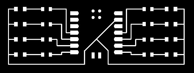
After five weeks of glorious trial and error, I decided to approach Week 6 with military precision. The goal: make and test the embedded microcontroller system I designed last week. The plan: start with the simple board of eight LEDs and, if everything went well, upgrade to the “Spider” version I proudly designed last week.
I headed over to Quentin’s website and created the two pngs needed for the process.

Then, I wrote my to-do list, checked the notes from Friday's open hours, packed my notebook, and swore that Monday morning I’d show up to the lab at 9:00 a.m. sharp. Confidence level: dangerously high.
Monday 9:10 a.m. - The Beginning
I step into the lab and to my surprise, there are 2 more people and everyone in the room has an Italian passport. It felt less like a fabrication lab and more like a regional embassy of the Italian Republic.
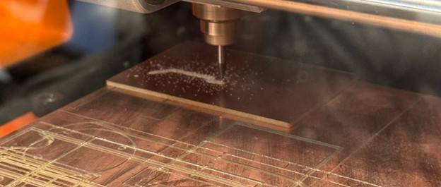
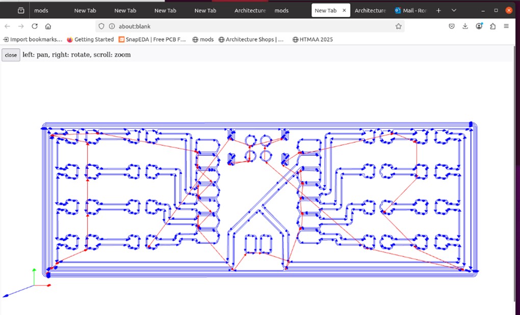
Before even touching the machine, I learned the ropes of PCB milling. The setup lives on the lab computer through the mods page - much like the vinyl cutter, you feed it a black-and-white PNG, calculate the toolpath, and send it to the device. Scrap copper boards are kept in the cabinet, and it’s worth measuring your design in KiCad before choosing one, since PCBs are just thin copper sheets over plastic and precision matters. The idea is simple: we’re carving away copper so the remaining traces act as neat, stable wires.
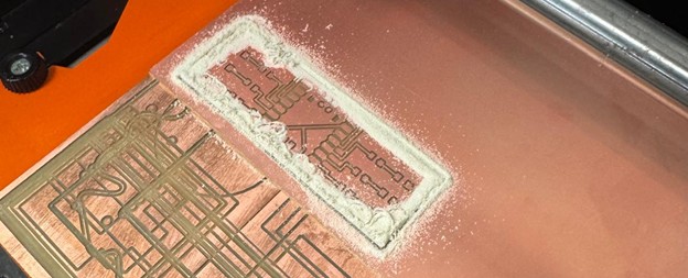
Anyhow, with my file ready and my board already designed, I head to the computer and prepare to use the Mondela SRM-20. There’s another Mondela in the corner, but word on the street is that it’s been “acting up.” I decide to trust my instincts and go for the working one. Or so I thought.
10:40 a.m. - The Unmovable Mondela
Fast-forward ninety minutes: the Mondela still refuses to start. The origin is unmovable, and my optimism slowly dissolving. We’ve checked the settings, the connection, the mood of the machine, nothing works.
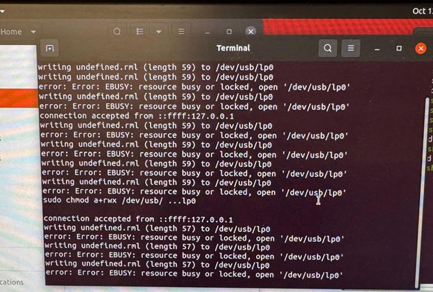
Then I open the terminal. Now, I like to think of myself as a minimally competent person, but every time I open a terminal I feel like I’m defusing a bomb in a foreign language. After a few confusing commands and a collective prayer… nothing changes.
11:00 a.m. - The good, old solution to every problem
The ultimate solution turns out to be refreshingly analog: turn the machine off and on, twice. And just like that, the led is NOT blinking anymore and the machine is ready to start carving. Victory, at least temporarily.
11:05 a.m. - Gathering Hope and Components
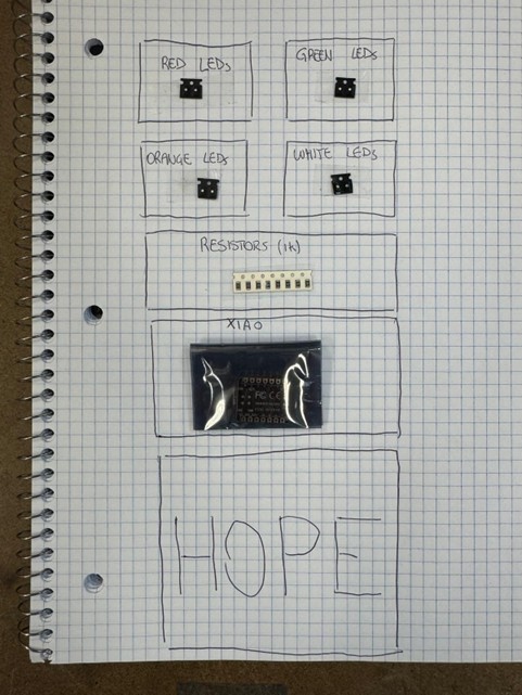
There is only one Mondela working, and I am the second in line, so I wait. While the machine runs, I collect resistors and LEDs, lining them up neatly. I also gather the most important component: a microcontroller Hope.
ACT II - CHAOS
11:30 a.m. - The First Casualty
The person before me retrieves their PCB… and half the traces are gone. A grim omen. We diagnose the issue: possibly too-thin traces in KiCad. I double-check mine. “Surely mine will be fine,” I whisper, tempting fate. I launch my job.
12:00 p.m. - Broken Traces, Part II
Same result. Traces broken, optimism shattered. I rewatch Quentin’s tutorial video three times, it all looks right. I’m stuck.
1:30 p.m. - The Arrival of Mighty Gert
When all seems lost, salvation arrives in the form of Gert. He examines our design for fifteen seconds and immediately spots the issue: we never generated the milling traces. The level of calm expertise is almost mythological. We fix the design, regenerate the toolpaths, and launch production again.
2:00 p.m. - Redemption (For Now)
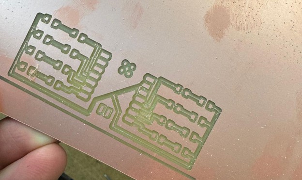
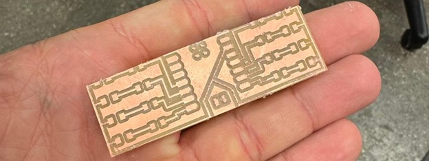
The board comes out beautifully. Smooth edges, clean cuts, symmetrical traces, a masterpiece (at least to me) of copper and perseverance. I take a victory photo and head to lunch feeling invincible.
3:30 p.m. - Warming Up the Iron
After lunch, it’s time to solder. But not before some practice: I grab my scrap board and start melting solder. Maybe I’m getting the hang of this. Maybe.
5:00 p.m. - The Great Short Circuit
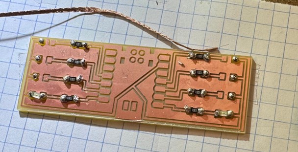
Confidence peaking, I start soldering the real board, resistors first, then LEDs.
After an hour, the moment of truth: I take the multimeter to test the connections.
Beep.
Beeeeeep.
Beeeeeeeeeeeeeeeeeeeeeeeeeeeeeeeeeeeeeep.
In fact, basically every combination of two points beeps. I’ve created not a circuit, but a unified field of conductivity. A masterpiece of short circuits.
6:30 p.m. - The Ill-Fated Decision
I now face a choice:
A) Start over.
B) Try to “fix” the existing board by removing excess solder bridges.
I pick option B, because at this point I’ve become emotionally attached to my small copper disaster.
ACT III - ACCEPTANCE
7:30 p.m. - The Second Attempt
After an hour, I’ve successfully removed zero bridges. So I decide to remake the board. Same file, same settings, same optimism (somehow). There is one person waiting in line, so I wait my turn, load the file, and press start.
8:30 p.m. - Murphy’s Law
The new board looks… worse. All the parameters are identical. The file is identical. The mill edge is sharp. Yet, the result? Unusable.
Two more people are now waiting to use the machine, so I step aside and return to my first board, trying once again to rescue it.
10:00 p.m. - The End of Hope
It’s over. Nothing works.
I have tried removing some connections but somehow I cannot do it correctly. I think the board cannot be used as it is, and probably it’s not even worth attaching the microcontroller. The Mondela hums mockingly in the background as I pack up my tools.
11:30 p.m. - Reflections from the Battlefield
Lying in bed, I can’t help but replay the day’s events, a full symphony of hope, solder, and short circuits. Precision machining, it turns out, isn’t always precise, and my soldering could be legally classified as abstract art.
Still, this week wasn’t a defeat. It was a crash course in the invisible craft behind electronics. Everything was new to me: the workflow from KiCad to milling, the delicate balance between heat and flux, the importance of clean traces and correct toolpaths. I began to see that in electronics, success doesn’t come from boldness but from meticulousness, from doublechecking trace width to meticulously place solder on the board.
And while I didn’t walk away with a working board, I did walk away with a working mindset: patient, methodical, and ready to improve.
Next time, the goal is simple: one LED. One glorious, blinking proof that learning through failure really works. This battle is not over yet.
Should you want to reproduce my work, here the files (proceed at your own risk): W6_BoardFiles.zip
Group Assignment
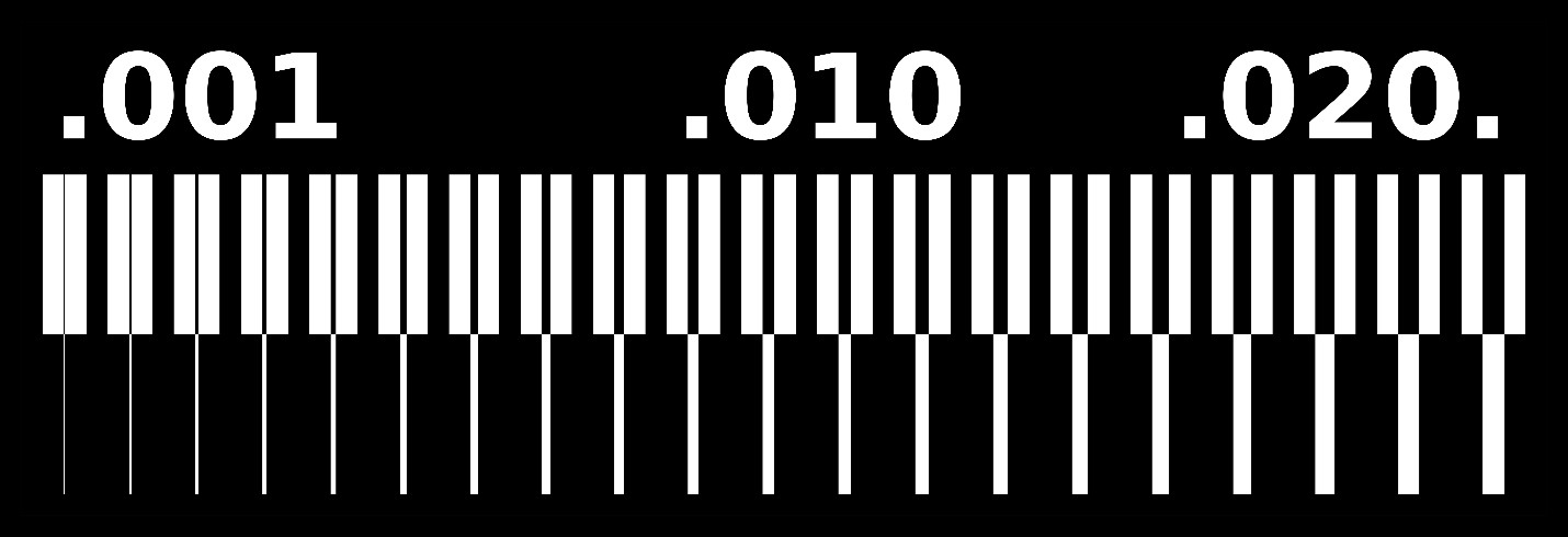
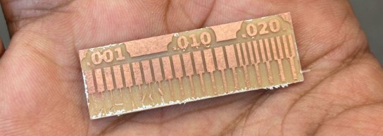
Anyhow, alongside the individual work, we also completed a group assignment focused on understanding the limits and capabilities of our in-house PCB production process. The task was twofold: first, to characterize the design rules for the Modela milling machine, and second, to submit a PCB design to a professional board house for comparison.
You can find a detailed overview of our shared workflow and results at this Architecture page.
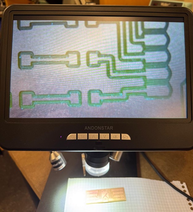
Through a series of test runs, we determined that the Modela can consistently produce traces as fine as 0.015 inches using a 1/64" milling bit. Attempts to go thinner led to common issues such as traces peeling off the copper substrate or misalignment errors in the CAM software.
To complete the exercise, Stasya submitted her PCB design to JLCPCB for professional manufacturing.
Final Project
Please note that Electronics Production has been part also of my final project. It is well documented in my final project page.