
Introduction
This week was all about input devices. The goal was to measure something by adding a sensor to a microcontroller I designed and then read the signal. I was away in Europe for job interviews and got back on Sunday, so I had a very compact runway: Monday and Tuesday to catch up on last week and complete this assignment. Coffee levels were high, optimism too.
Individual Assignment
Board Design
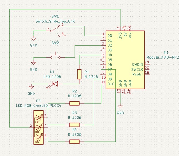
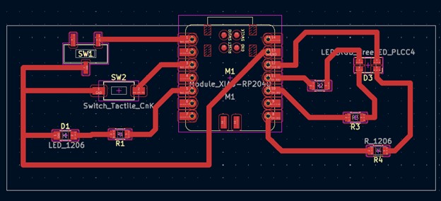
Week 6 and I had a memorable time together, as I made many mistakes learned a lot of lessons. So I started over for Week 8 with a calmer, sturdier layout. The design is intentionally simple: one push button and one slide switch, a white LED, and an RGB LED. The goal is straightforward: program basic interactions between the inputs and the LEDs, without turning the copper pour into one giant short like two weeks ago. Here some adjustments I made this time:
- Wider traces (~1 mm) for friendlier milling and soldering.
- No traces hugging the edges; extra clearance all around.
- Part orientation chosen to avoid awkward gaps and accidental bridges.
Files for milling: W8_BoardFiles.zip
Milling the Board
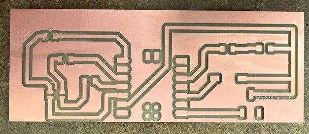
In Week 6 it took multiple attempts to get a usable board. This time I approached the Roland Modela with respect and a tiny bit of fear. The “lid-open” blinking saga made a cameo; the fix, learned the hard way: power cycle and move on. No one hour of existential troubleshooting this time (btw still not clear to me why this happens).
Ten quiet minutes later: crisp traces, calm heart rate.
Soldering
I will admit it: I was worried I would drown the board in solder. At that exact moment, providence sent me Gert.
Huge shoutout to Gert - he generously spent about an hour guiding me through good technique, joint inspection, and patience. Legend. Here the soldered board, as well as most of Gert's feedback on my soldering.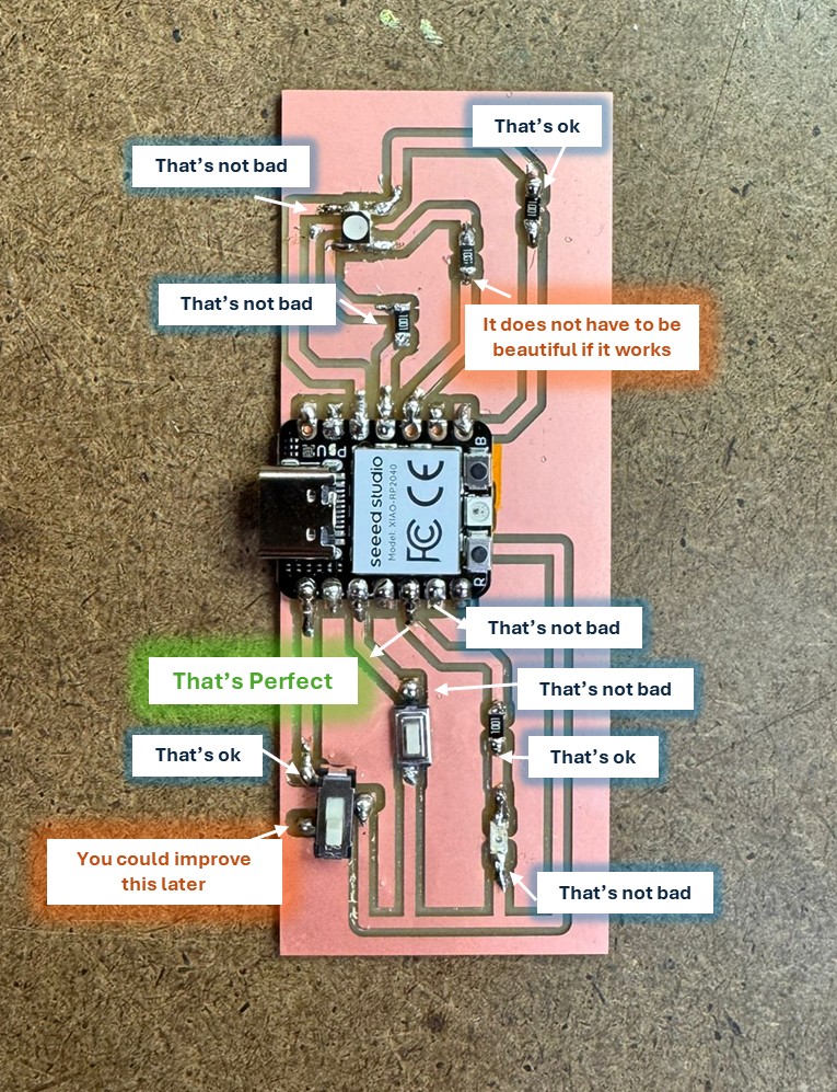
Connecting the Board
On first plug-in, the board lit up. Then the Arduino IDE mysteriously stopped showing any serial port
haha! this is the plot twist that destiny reserved for me this week!
My troubleshooting tour, powered by curiosity and several tabs:
- Reconnected the board.
- Swapped the cable.
- Pressed reset.
- Reinstalled RP2040 board libraries.
- Tried another microcontroller. That one showed up.
- Rebooted the laptop. (I mean at this point why not... )
- Entered bootloader mode and reflashed via UF2, following this guide: Seeed XIAO RP2040 docs.
After more than an hour of back-and-forth, it finally reappeared. Relief was immediate and visible.
Programming
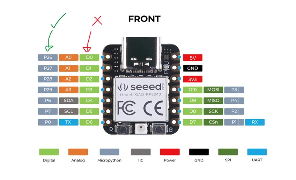
First surprise: pin naming. I assumed the D numbers were what the Arduino core expected. In reality, I had to use the P numbers in code for this setup.
Then, I pushed some code to check that the board was working properly:
- Turned on the white LED.
- Blinked each channel of the RGB LED.
- Blinked RGB channels in sequence at 1 second interval.
- Switched blink frequency from 1 second to 0.5 second using the slide switch.
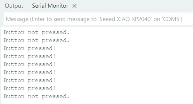
- Read the push button state.
- Rotated RGB colors when the button was pressed.
I am not a coder, so I leaned on AI for a few quick snippets. For the button read, Irelied on old friend Google and wrote a minimal sketch myself:
Button Read — Minimal Sketch
const int buttonPin = 28;
bool buttonState = 0;

void setup() {
  pinMode(buttonPin, INPUT_PULLUP);
  Serial.begin(9600);
}

void loop() {
  buttonState = digitalRead(buttonPin);
  if (buttonState == LOW) {
    Serial.println("Button pressed!");
  } else {
    Serial.println("Button not pressed.");
  }
  delay(200);
}
Group Assignment
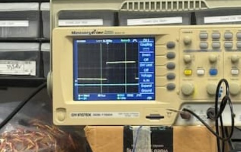
This week, our group used an oscilloscope to probe a motion sensor’s analog and digital outputs. The yellow trace showed voltage rising with motion and dropping when still, while the blue trace served as a ground reference. After wiring power, ground, and output to the scope, we noted that the sensor could detect movement even inside a box and that its digital signal showed a brief one-to-two-second delay.
Final Project
Please note that Input Devices are a key part of my final project. It is well documented in my final project page.