Introduction
This week’s individual assignment was to add an output device to a custom microcontroller board and program it to perform a task. The group assignment focused on measuring the power consumption of an output device.
Individual Assignment
Output Programming
Approach
After the struggles of Week 6, when I spent countless hours debugging a simple board, and given that I recently designed a new one for last week’s assignment, I decided to shift my focus. Since I’m also still catching up on the Week 7 OSB project (which, by the time you read this, will already be uploaded on my website), I used this week as an opportunity to deepen my programming skills rather than redesign another board.
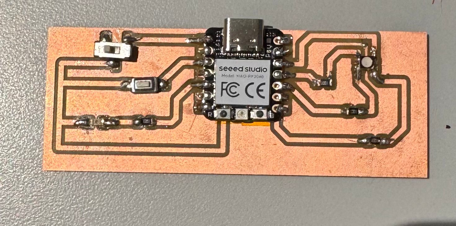
The board I used is the same as last week’s: it includes one switch, one press button, a standard LED, and an RGB LED. The board itself doesn’t serve a specific purpose, it was mainly a test platform to improve my fabrication workflow. I had already verified that all components were working correctly, so I dedicated this week to writing and testing new programs to make the LEDs interact dynamically with the buttons. I also made a point of coding manually (aided by AI) to strengthen my understanding of the logic and syntax behind these interactions.
Code 1 – Reading the Button
The first step was simply to check if the button input was still being detected properly. After a few connection hiccups, everything worked as expected. Here’s the code I used to read the button’s state:
const int buttonPin = 28;
bool buttonState = 0;

void setup() {
  pinMode(buttonPin, INPUT_PULLUP);
  Serial.begin(9600);
}

void loop() {
  buttonState = digitalRead(buttonPin);
  if (buttonState == LOW) {
    Serial.println("Button pressed!");
  } else {
    Serial.println("Button not pressed.");
  }

  delay(200);
}
Code 2 – Cycling RGB LED Colors with Button Clicks
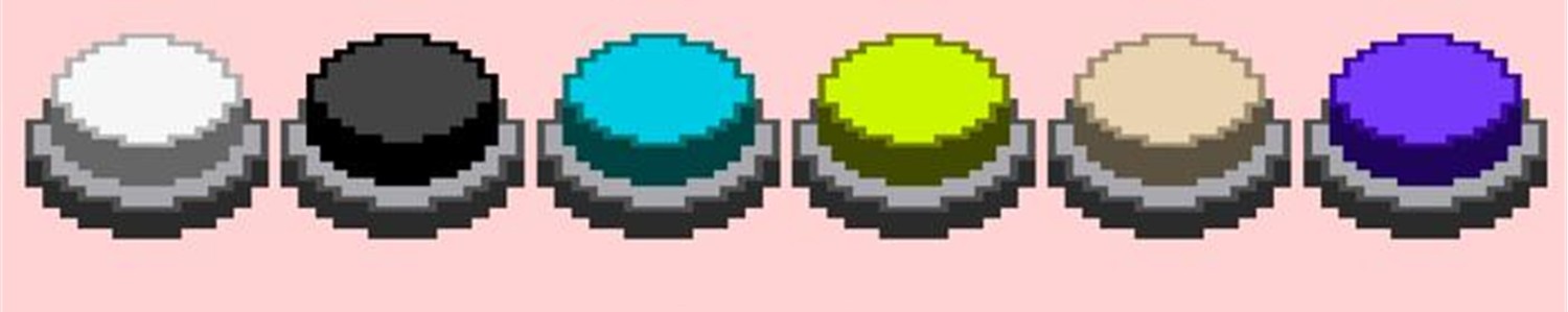
Next, I programmed the board so that every press of the button changes the RGB LED’s color. I also introduced mixed colors (yellow, cyan, and magenta) by combining two of the RGB channels at a time. The sequence cycles through red, yellow, green, cyan, blue, and magenta before looping back to red.
const int redPin   = 1;
const int greenPin = 4;
const int bluePin  = 3;
const int buttonPin = A2;

const unsigned long debounceMs = 25;

int colorIndex = 0;
int stableState = HIGH;
int lastReading = HIGH;
unsigned long lastChangeMs = 0;

void setup() {
  pinMode(redPin,   OUTPUT);
  pinMode(greenPin, OUTPUT);
  pinMode(bluePin,  OUTPUT);

  pinMode(buttonPin, INPUT_PULLUP);

  Serial.begin(115200);
  setColor(255, 0, 0); // start at Red
  Serial.println("Press the button to advance colors.");
}

void loop() {
  int reading = digitalRead(buttonPin);
  if (reading != lastReading) {
    lastChangeMs = millis();
    lastReading = reading;
  }

  if (millis() - lastChangeMs > debounceMs) {
    if (reading != stableState) {
      // Edge detected
      stableState = reading;

      if (stableState == LOW) {
        advanceColor();
      }
    }
  }
}

void advanceColor() {
  colorIndex = (colorIndex + 1) % 6;
  switch (colorIndex) {
    case 0: setColor(255, 0,   0);   break; // Red
    case 1: setColor(255, 255, 0);   break; // Yellow
    case 2: setColor(0,   255, 0);   break; // Green
    case 3: setColor(0,   255, 255); break; // Cyan
    case 4: setColor(0,   0,   255); break; // Blue
    case 5: setColor(255, 0,   255); break; // Magenta
  }
  Serial.print("Color index: "); Serial.println(colorIndex);
}

// Common-cathode version (0..255 brightness)
void setColor(uint8_t r, uint8_t g, uint8_t b) {
  analogWrite(redPin,   r);
  analogWrite(greenPin, g);
  analogWrite(bluePin,  b);
}
Code 3 – Adding Interaction with the Switch Button
Finally, I integrated the switch button into the logic. The goal was to make the switch control whether the LED is blinking or solid, while the press button continues to change the color. When the switch is open, the LED shows a solid color; when closed, it blinks at 0.5 second intervals.
const int redPin   = 1;
const int greenPin = 4;
const int bluePin  = 3;
const int buttonPin = A2;
const int switchPin = 26;

const unsigned long debounceMs = 25;
int stableBtnState = HIGH;
int lastBtnReading = HIGH;
unsigned long lastBtnChangeMs = 0;

const unsigned long blinkIntervalMs = 500; // 0.5 s
unsigned long lastBlinkToggleMs = 0;
bool blinkVisible = true;

int colorIndex = 0;

void setup() {
  pinMode(redPin,   OUTPUT);
  pinMode(greenPin, OUTPUT);
  pinMode(bluePin,  OUTPUT);

  pinMode(buttonPin, INPUT_PULLUP);
  pinMode(switchPin, INPUT_PULLUP);

  applyColor(255, 0, 0, /*visible=*/true);
}

void loop() {
  bool switchClosed = (digitalRead(switchPin) == LOW);

  int reading = digitalRead(buttonPin);
  if (reading != lastBtnReading) {
    lastBtnChangeMs = millis();
    lastBtnReading = reading;
  }
  if (millis() - lastBtnChangeMs > debounceMs) {
    if (reading != stableBtnState) {
      stableBtnState = reading;
      if (stableBtnState == LOW) {
        advanceColor();
      }
    }
  }

  bool shouldShow = true;
  if (switchClosed) {
    if (millis() - lastBlinkToggleMs >= blinkIntervalMs) {
      lastBlinkToggleMs = millis();
      blinkVisible = !blinkVisible;
    }
    shouldShow = blinkVisible;
  } else {
    // Solid color mode
    shouldShow = true;
  }

  uint8_t r, g, b;
  indexToColor(colorIndex, r, g, b);
  applyColor(r, g, b, shouldShow);
}

void advanceColor() {
  colorIndex = (colorIndex + 1) % 6;
}

void indexToColor(int idx, uint8_t &r, uint8_t &g, uint8_t &b) {
  switch (idx) {
    case 0: r=255; g=0;   b=0;   break; // Red
    case 1: r=255; g=255; b=0;   break; // Yellow
    case 2: r=0;   g=255; b=0;   break; // Green
    case 3: r=0;   g=255; b=255; break; // Cyan
    case 4: r=0;   g=0;   b=255; break; // Blue
    case 5: r=255; g=0;   b=255; break; // Magenta
  }
}

void applyColor(uint8_t r, uint8_t g, uint8_t b, bool visible) {
  if (!visible) {
    analogWrite(redPin,   0);
    analogWrite(greenPin, 0);
    analogWrite(bluePin,  0);
    return;
  }
  analogWrite(redPin,   r);
  analogWrite(greenPin, g);
  analogWrite(bluePin,  b);
}
Group Assignment
On Thursday afternoon, our group met with Gert for a short practical session on basic electronics. He showed us how a stepper motor behaves when you change the voltage, pointing out how higher voltage affects how the motor runs and how much power it uses.
He then used an LED to illustrate what happens when electrical limits are ignored. By slowly increasing the voltage beyond what the LED could handle, he showed how it eventually failed and burned out.
Final Project
Please note that Output Devices are a key part of my final project. It is well documented in my final project page.