Communications
OSI Model
 source: https://www.cloudflare.com/learning/ddos/glossary/open-systems-interconnection-model-osi/
In short: don’t let the mess from the lower layers impact the abstraction level of your current layer.
Physical layer
At the very bottom of any communication system, there is a signal varying over time, transported over a physical channel. A protocol’s physical OSI layer deals with all properties of this channel and prescribes a way to use it for transmission.
Channel capacity
The theoretical upper bound for a channel’s net bit rate in bits/s:
Where:
- B: bandwidth (Hertz)
- SNR: signal to noise ratio
Conclusions:
- For faster bit rate, we can work on the SNR or be more greedy on bandwidth (if available)
- If bit rate is not critical, transmission can (almost) always be achieved no matter how bad the SNR. For instance, Voyager 1 used to transmit at 21.6 kb/s and is now down to 160 b/s.
Spectrum
When looking at the transmitted signal in the frequency domain, a few things become obvious:
- Some parts of the spectrum are not available or can’t be physically reached (high frequencies)
- Perfect square waves cannot exist in the real world!
- Narrowband modulation is convenient for slicing up bands in several channels
Copper wires
This is the earliest example of physical layer, starting with telegraph lines. Information is usually carried by a voltage varying over time, sent from the transmitter to the receiver.
A popular model for the impedance of an element of copper line is an RLC(+G) circuit:
![]() source: https://upload.wikimedia.org/wikipedia/commons/1/11/Transmission_line_element.svg
source: https://upload.wikimedia.org/wikipedia/commons/1/11/Transmission_line_element.svg
Integrating this element over the whole line and solving the so-called telegrapher’s equations provides us with the characteristic impedance of the line:
This is the perceived impedance from the emitter’s viewpoint, if the line properly terminated with an impedance-matched termination resistor. Otherwise, reflections come back and degrade the signal, leading to perceived noise.
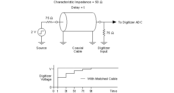 source: https://zone.ni.com/reference/en-XX/help/370592AB-01/digitizers/impedance_and_impedance_matching/
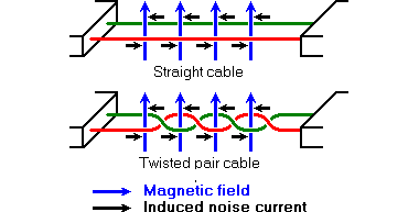
One good practice is to twist the wire pair to mitigate interference caused by an external magnetic flux.
Radio
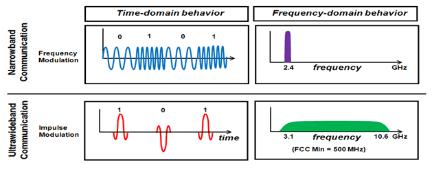
Radio domain is dominated by narrowband communication, so that several bands can be defined and used for different purposes. Current applications for ultra wideband are mostly radar and tracking.
 source: https://www.researchgate.net/profile/Rashid-Fayadh/publication/286584218
Modern narrowband communication encodes several bits into a single symbol, mapped to a specific amplitude and phase applied on the carrier wave.
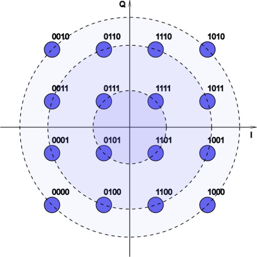 source: A. Skidin, O. Sidelnikov, M. Fedoruk, and S. Turitsyn, “Mitigation of nonlinear transmission effects for OFDM 16-QAM optical signal using adaptive modulation,” Opt. Express 24, 30296-30308 (2016).
Orthogonal frequency-division multiplexing (OFDM) is now widely used in 4G (and 5G) networks, it’s the most efficient scheme for packing sub-carriers in a limited band. The sub-carriers are seemingly overlapping each other but are carefully designed to be fully recoverable at demodulation, providing an effective bandwidth of exactly one OFDM band.
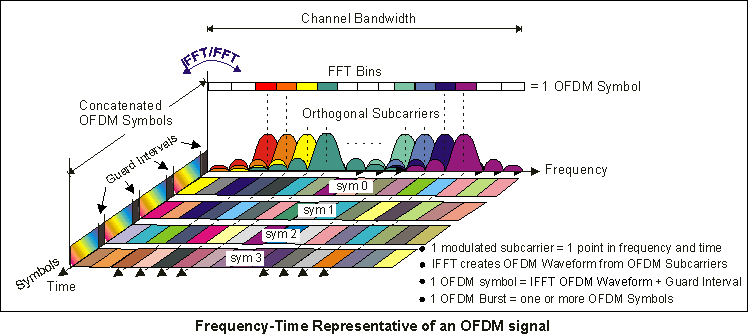 source: http://rfmw.em.keysight.com/wireless/helpfiles/89600b/webhelp/subsystems/wlan-ofdm/Content/ofdm_basicprinciplesoverview.htm
Another important modern feature is multiple-input, multiple-output (MIMO), in which an array of emitting antenna communicates with an array of receivers. With various multiplexing schemes (frequency and orthogonal codes), the mangled data can be perfectly recovered, leading to a linear increase in throughput.
Software defined radios (SDR) are amazing little devices that can process the baseband signal in arbitrary ways, allowing prototyping of novel protocols. The processing of the captured samples can be offloaded to a computer, or performed by an embedded device (e.g. FPGA).
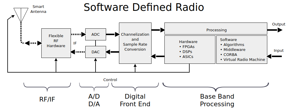 source: https://payatu.com/blog/appar/iot-security-%E2%80%93-part-8-introduction-to-software-defined-radio-sdr
Frameworks and tools for SDR:
Optical
 source: https://news.fit.edu/archive/cant-live-without-fiber-optics/
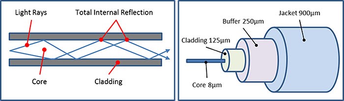
In optical systems, information is carried by visible wavelengths. Compared with radio frequencies, the potential increase in bitrate is obvious, although there are serious challenges to overcome. As visible light is easily blocked, it needs to guided in a medium with low dispersion and attenuation. The most popular medium is now optical fibers, which make use of total reflection between the core and cladding due to a difference in refractive index so that very efficient propagation modes appear at some given frequencies.
- Bit rate world record: a whopping 172 tb/s using spatial multiplexing in only 3 cores, 1 mode in each.
- Quantum entanglement: entangled single photon transmission
- Starlink: achieves lower latency than grounded fiber optics thanks to the lower dispersion in the (relative) vacuum at that altitude.
Datalink layer: making chips talk
Note: in the following, master/slave terminology (M/S) is replaced with controller/peripheral (C/P).
Synchronous VS asynchronous
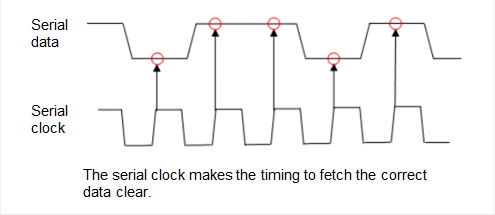
When microcontrollers communicate, they need to agree on timing, as they each (presumably) run on their own clock. This timing information can be implicit or explicit, leading to two different strategies:
- Synchronous: both parties remain in sync, usually thanks to an extra transmission line providing clock ticks (when to sample the data).
- Asynchronous: next data block could arrive any time, and is delimited by a start marker, and possibly stop marker (unless data length is known beforehand).
 source: https://en-support.renesas.com/knowledgeBase/17943143
Another strategy is to embed the clock information within the data, as achieved by Manchester code; this is an example of isochronous protocol.
 source: https://en.wikipedia.org/wiki/Self-clocking_signal
Half Duplex VS full Duplex
Either both parties can transmit at the same time in a dedicated channel (full duplex), or need to share the same channel and transmit in alternation (half duplex). Full duplex can always achieve faster transmit speeds as long as flow control is carefully designed.
Error detection
Checking for data integrity can be implemented in almost any of the OSI layers, but the datalink layer is a good place to start. Adding metadata to a message can achieve two things:
- Error detection: easily implemented with a checksum, this lets the receiving end simply drop the message in case of inconsistency. When the protocol is based on acknowledgements, data can be easily retransmitted until the ACK is received.
- Error correction codes: introduce enough redundancy in the message to recover from sparse errors. The amount of overhead can be designed to guarantee a specific error resilience.
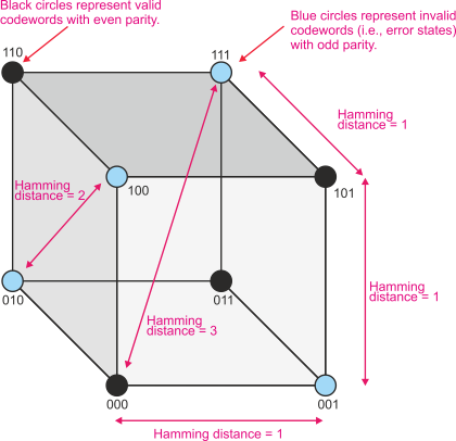 source: http://alanclements.org/errordetectingcodes.html
UART
The asynchronous, full-duplex, 8-bit word protocol that we all know and love. The transmission line is normally HIGH, then a start bit drives the line LOW, followed by 8-bits of data. After this, there is usually 1 stop bit or more, and an optional parity bit to help with error detection.
I2C
I2C is a half-duplex open-drain, synchronous protocol for communication between multiple controllers and multiple peripherals. An pull-up resistor is needed somewhere on the line, as it can only be pulled down by the open-drains.
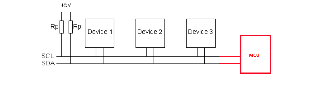 source: https://www.robot-electronics.co.uk/i2c-tutorial
SPI
SPI is a synchronous and full-duplex protocol for single-controller and multiple peripherals. Notable examples of SPI peripherals include:
- flash/EEPROM
- SD cards
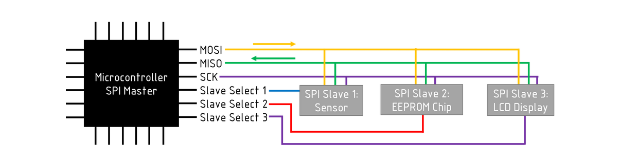 source: https://maker.pro/custom/tutorial/an-introduction-to-spi-communications-protocol
CAN, LIN
Both of these robust protocols are popular in the automotive industry. The use of a single bus to control almost all functionalities of the car was a significant simplification for manufacturing. LIN is simpler to implement as it requires a single communication cable, and is now used for non-critical peripherals.
RS232, RS422 and RS485
Those interface protocols define the physical layer for basic serial communication. In brief, RS232 is full-duplex, while RS485 is half-duplex and makes use of a balanced pair, more robust against interference. RS422 takes the best of both worlds with full-duplex balanced pairs.
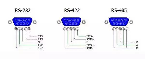 source: https://www.optcore.net/difference-between-rs-232-rs-422-and-rs-485/
USB
Universal Serial Bus (USB) dominates when it comes to interfacing with consumer electronics. Up to USB 2.0, it comprised 4-pins: 5V/GND, and a half-duplex differential line D+/D-. USB 3.0 introduced faster rates and more pins to enable full-duplex.
There is a long list of device classes supported by USB. The most relevant ones here are:
- Communications Device Class (CDC): emulates a serial line over USB, with a fictive baudrate and settings (useful for implementing your own USB serial adapter).
- Human Interface Device (HID): keyboard, mouse, etc.
- Mass Storage Device: detected by the OS as a storage device, usually for interfacing with flash memory or a hard drive.
A good place to start playing with USB is the SAMD microcontroller family, as it has hardware support for USB.
Other protocols
- I2S for audio
- MQTT for IoT
- Bluetooth for short-mid range wireless
- Lora for long range, low bandwidth wireless
- NFC for very short range, usually for token exchange